
Chapter 8
Qualitative and Semiquantitative Methods for Natech Risk Assessment
E. Krausmann*
K.-E. Köppke**
R. Fendler†
A.M. Cruz‡
Abstract
Risk assessment is a prerequisite for understanding the Natech risk and for determining if and which prevention and preparedness measures should be implemented to reduce the risk. The analysis of multihazard risks is a highly complex task and there is no consolidated methodology for assessing the Natech risk. This chapter introduces selected qualitative and semiquantitative Natech risk-analysis methodologies, approaches, and tools of varying levels of resolution. The outcome of these methodologies can be used for evaluating the risk in accordance with the risk-acceptability criteria in place.
Keywords
risk analysis
qualitative
semiquantitative
RAPID-N
fragility curve
PANR
Risk assessment is a prerequisite for understanding the Natech risk and for determining if and which prevention and preparedness measures should be implemented to reduce the risk. The analysis of multihazard risks is a highly complex task and there is no consolidated methodology for assessing the Natech risk. This chapter introduces selected qualitative and semiquantitative Natech risk-analysis methodologies, approaches, and tools of varying levels of resolution. The outcome of these methodologies can be used for evaluating the risk in accordance with the risk-acceptability criteria in place.
8.1. RAPID-N
The identification of potentially Natech-prone areas and the determination of the associated risk level are the first steps toward managing Natech risks. As Krausmann and Baranzini (2012) note, hardly any Natech risk maps exist in EU Member States and OECD Member Countries. In few countries, maps with overlays of natural and technological hazards were created to provide an indication to government authorities of where multihazard risks could exist. These hazard maps do, however, not consider site-specific features or the interaction between natural and technological hazards. The development of a Natech risk assessment and mapping capability is considered a high-priority need by authorities for effectively reducing Natech risks.
Following calls by government, the European Commission’s Joint Research Centre has developed a semiquantitative methodology for Natech risk analysis and mapping which has been implemented as a web-based software framework called RAPID-N. It is freely available via prior user registration and authorization at http://rapidn.jrc.ec.europa.eu. RAPID-N allows the quick analysis of Natech risks at local (single installation) or regional (multiple assets) level with a minimum of data. It features a user-friendly interface with advanced data entry, visualization, and analysis tools. In order to preserve confidentiality, it supports data protection and access restrictions for critical information, such as industrial plant data and the associated risk assessment.
RAPID-N was designed to support different natural hazards and industrial equipment types. Estimating the Natech risk and mapping it in a web-based environment, it can not only support land-use- and emergency planning, but also Natech damage and consequence analysis immediately after a natural event. The latter is fundamental for first responders who require an assessment of the dangers of secondary hazards from industrial plants following a natural disaster before dispatching rescue teams. It could also provide a means for authorities to warn the population in the vicinity of the installation in a timely manner.
The structure of RAPID-N is based on four self-contained but interconnected modules, each of which carries out specific tasks in support of the Natech risk-analysis process. These modules are briefly described in the following sections. For a detailed description of the framework and guidance on its use, the reader is referred to Girgin and Krausmann (2013) and Girgin (2012). In Chapter 10 a full case-study application of RAPID-N is presented for earthquake impact on a chemical installation containing flammable and toxic substances.
8.1.1. Scientific Module
The scientific module provides all underlying computational support for the RAPID-N simulations (data handling, statistics, mapping, etc.). The module also includes the so-called property-definition and -estimation framework, which forms the very basis of RAPID-N’s Natech risk-analysis functionality. Natural hazards, industrial plants and their units, and hazardous substances are all described via their properties, for example, hazard severity, site characteristics, boiling point, etc. These characteristics are not always known in sufficient detail for RAPID-N to run a simulation. Hence, the tool uses property estimators to fill existing data gaps based on available scientific estimation methods and equations. For example, RAPID-N can estimate the peak ground acceleration at the hazardous installation based on the epicentral severity and the use of automatically selected attenuation equations valid for the given geographic region. An example of a very simple property estimator would be the automatic calculation of the tank diameter from its volume. Instead of analytical equations or complex mathematical functions, default values of the properties can also be specified (e.g., the default ambient temperature). Rather than using hard-coded functions, RAPID-N also performs the damage and risk analysis with property estimators. The advantage of this implementation is twofold: (1) it reduces the amount of data to be provided by the user, and (2) the Natech risk analysis is rendered extremely flexible as alternative assessment methods with varying complexity can be implemented easily by the user. The estimation framework also allows the definition of custom properties to support additional analysis needs. Uncertainty in numerical data can be specified using fuzzy numbers, which are automatically taken into consideration by RAPID-N while performing numerical calculations. Wherever possible, the calculation results are also reported as fuzzy numbers to provide an indication of the uncertainty.
8.1.2. Industrial Plants and Units Module
For assessing the Natech risk, RAPID-N estimates the damage severity and probability for industrial-plant equipment under natural-hazard loading. For this purpose, the tool needs information on the geographic location of the plant and the characteristics of the plant units, such as type of equipment, dimensions, structural properties, operating and storage conditions, and hazardous substances contained in the unit. Existing safety measures, for example, dikes around storage tanks, can also be specified. RAPID-N includes a special mapping tool that helps the user to quickly locate and delineate the boundaries of industrial installations and identify plant units using publicly available satellite imagery. Once the type and total quantity of hazardous substance has been defined, RAPID-N calculates the amount of substance involved in the accident and used for the consequence analysis based on operating/storage conditions. Fig. 8.1 gives an example of a RAPID-N interface showing both user-defined and estimated plant unit information. Process units located at fixed chemical installations and onshore pipelines are currently supported.
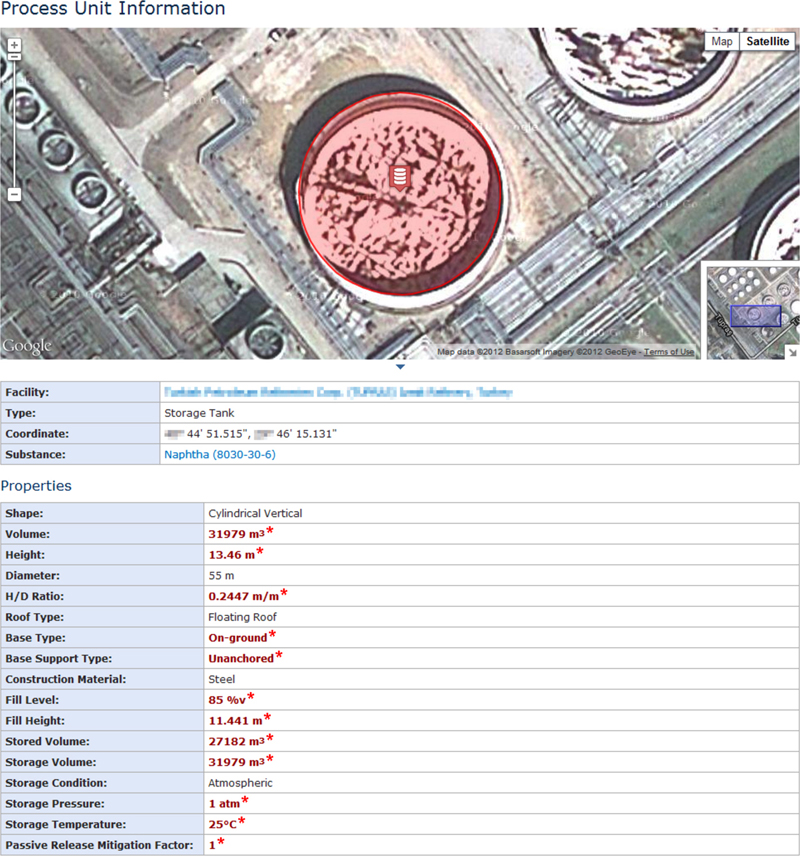
Figure 8.1 Example of Plant Unit Information
The asterisk designates data estimated or assigned as default values by RAPID-N in the absence of user-defined information.
The asterisk designates data estimated or assigned as default values by RAPID-N in the absence of user-defined information.
In-depth information on plant and equipment characteristics is usually difficult to obtain as it is often considered proprietary and is therefore closely held by industry. If no equipment information is available at all, user-defined typical plant units can be assigned to a hazardous plant to allow a rough estimate of the Natech risk. These typical plant units can be defined for specific industrial activities, for example, typical storage tanks for refineries or petrochemical facilities.
8.1.3. Natural-Hazards Module
Source and onsite data on the natural-hazard accident initiator are provided by RAPID-N’s natural-hazards module. The source data include information on the characteristics of the natural hazard, for example, earthquake coordinates, focal depth, and magnitude. However, for the Natech risk analysis the source characteristics are secondary. Rather, the natural-hazard severity data at the location of the hazardous installation are required. RAPID-N can estimate the onsite natural-hazard severity by using estimation equations that are selected automatically by the data-estimation framework based on source parameters, location, and geographic region. For example, RAPID-N uses attenuation equations for estimating the seismic forces at a specific distance from the epicenter. RAPID-N also supports the direct inputting of the onsite natural-hazard severity, if known to the user, or the use of earthquake hazard maps (e.g., USGS ShakeMaps) for which local hazard parameters are calculated by interpolation of available map data.
RAPID-N currently contains data and hazard-intensity estimation methods that focus on earthquakes as the proof-of-concept hazard. Its natural-hazard database includes source data of worldwide earthquakes with a magnitude >5.5 since the early 1970s for use in historical scenario assessment. RAPID-N also monitors the earthquake catalogs of the United States Geological Survey (USGS) and the European-Mediterranean Seismological Centre (EMSC), and once new earthquake data become available they are automatically included in RAPID-N’s earthquake database. At the time of writing this book, work has been launched to provide data and methods for extending the tool to flood Natech risk analysis and mapping.
8.1.4. Natech Risk-Analysis Module
This module constitutes the very core of RAPID-N. It estimates equipment damage caused by a natural hazard, analyzes the most likely consequences, and visualizes the outcome of the analyses on a map showing possible impact zones.
The analysis process starts with the determination of the damage probability and severity of equipment located at industrial plants impacted by a natural hazard. For this purpose, RAPID-N uses fragility curves which relate onsite hazard-severity parameters (e.g., peak ground acceleration) to the probability of damage for a given damage severity (Fig. 8.2). In order to be able to define damage-state-specific Natech scenarios, RAPID-N uses discrete damage states, examples of which are given in Section 7.3 and in FEMA (2003). Since criteria for damage classification also depend on the target application area (e.g., analysis of hazardous-materials releases vs. economic cost of damage) RAPID-N supports multiple damage classifications to allow the user to customize the risk analysis. If the user prefers, RAPID-N can automatically select for each plant unit an appropriate fragility curve.

Figure 8.2 Fragility Curve for an Anchored Steel Storage Tank Subjected to Earthquake Shaking
Once the level of damage is known, it needs to be related to type and severity of loss of containment to identify the consequences in terms of toxic dispersion, fire, or explosion. RAPID-N associates risk states to the predicted damage severities which in practice are simplified consequence scenarios. These risk states define the magnitude of loss of containment, depending on the substance hazard and the operating or storage conditions, and the release and ignition probabilities where applicable. Multiple risk states with different scenario parameters and validity conditions can be defined for a specific damage state. The most appropriate risk state for further analysis is automatically determined by RAPID-N considering plant unit characteristics, damage state, and validity conditions of the risk states.
Based on the selected risk state, RAPID-N calculates the amount of substance involved in the accident, which is used for the consequence analysis depending on operating/storage conditions. The consequences are estimated by means of a scenario-specific, dynamically-generated consequence model that is formed by RAPID-N using the consequence-analysis methods and equations available in the database of the property-estimation framework. As proof of concept, the framework includes the US EPA RMP Guidance for Offsite Consequence Analysis methodology (US EPA, 1999) for analyzing the impacts of the probable Natech accident scenarios. While it is not a full-fledged quantitative analysis methodology, it is an example of a simple but functional approach to consequence analysis that allows the estimation of the distances to severity endpoints. For toxic releases, the endpoints are either Emergency Response Planning Guideline 2 (ERPG-2) or immediately dangerous to life and health (IDLH) toxic concentrations. For flammable substances, the endpoints to heat radiation levels of 5 kW/m2 for 40 s (corresponding to second degree burns) and overpressures of 7 kPa (1 psi) for vapor cloud explosions are calculated. The user can easily customize the endpoint criteria or introduce different consequence-analysis models, if so preferred. User-defined modifications to the RAPID-N framework do not affect other users, leaving room for experimenting with novel Natech risk-analysis approaches.
The RAPID-N output is presented as a summary report including all parameters used in the risk analysis and detailed results, as well as an interactive risk map that displays the severity, probabilities, and impact zones of the simulated Natech events. Fig. 8.3 gives an example of a case-study output. If the risk assessment involves multiple plant units, areas which might be affected by releases from several units can be easily identified in the output map. Moreover, as the risk of cascading effects during Natech events is high, RAPID-N can also be used as a screening tool for identifying potential problem areas due to domino effects. For example, if released flammable substances ignite, RAPID-N shows if other infrastructures fall within the fire’s impact zone. This gives an indication of where attention should be paid and where further in-depth analysis might be warranted.
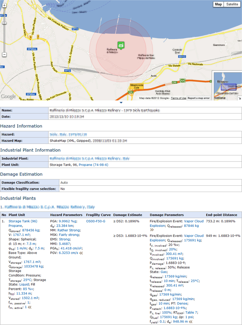
Figure 8.3 Example Output of a RAPID-N Earthquake Natech Case Study
8.1.5. Outlook
The current version of RAPID-N supports earthquake Natech risk analysis and mapping for fixed chemical installations and onshore pipeline systems. The next release of the tool will incorporate floods as additional Natech accident trigger. RAPID-N will then also be able to calculate individual and societal risk in addition to impact zones in an attempt to move toward a more quantitative treatment of the problem. An automated analysis function will also be implemented to analyze Natech risk for facilities available in the RAPID-N database immediately after the occurrence of a major natural event, so that competent authorities, first responders and other interested parties can be alerted quickly to ensure fast protective action if required.
8.2. PANR
A qualitative methodology for the preliminary assessment of Natech risk (PANR) in urban areas was proposed by Cruz and Okada (2008). The PANR methodology involves identifying, quantifying, and analyzing the risk posed by the presence of hazardous materials in a territory subject to natural hazards to local exposed elements in a community. PANR defines risk as a function of the hazard (magnitude and probability) and the vulnerability of the elements exposed (consequences, their severity, and probability) to the hazards (both the natural and secondary hazards from any chemical accidents and their domino effects).
The PANR methodology involves several steps including data collection and inventory development, hazard identification and vulnerability analysis, and estimation of a Natech risk index for each storage tank containing hazmats in a territory. Once the Natech risk-index values have been estimated, it is possible to identify those areas with high Natech risk (Natech hotspots). Using the previous expression for risk, the Natech risk index (NRIi) for each hazmat containing storage tank i in a territory for a given natural disaster scenario is defined as follows:
where HRL is a score that accounts for the hazmat-release likelihood, given the natural-hazard event; D is a score that accounts for the effects of potential domino chemical accidents; Area-sc is a score that measures the potential consequences of the hazmat release from each tank i on the population in the directly affected area given the natural-disaster scenario; and C is a score that measures the potential consequences of the hazmat release from each tank i on essential facilities located within the directly impacted area that are critical for the safety and well-being of the community and the environment given the natural-disaster scenario. Fig. 8.4 shows a schematic of these relationships.
The PANR methodology was developed as a diagnostic tool for local communities and is intended to promote the participation in the assessment process of local government officials and first responders in consultation with community members, industrial-facility operators, and experts. The PANR methodology was tested among representatives of European Union Member States during an international workshop at the Joint Research Centre of the European Commission in 2007 (Cruz and Krausmann, 2008) to identify minimum skills and knowledge needed to carry out the assessment.

Figure 8.4 Graphic Representation for the Natech Risk Index (NRIi) for Tank i (Base Map ©2016 Google, Zenrin)
Improvements to the methodology were proposed by Cruz and Suda (2015) by introducing relationships to estimate D, Area-sc, and C, as well as implementing PANR into the Joint Research Centre’s RAPID-N tool (Section 8.1) for the estimation of the HRL values. The authors applied the methodology to an industrial park and neighboring residential areas in Kobe, Japan, and compared the results obtained with estimates of NRIs for past Natech accidents in Japan. Data for the study were collected through interviews, survey questionnaires, site visits, review of government reports, city plans, chemical-accident rules and regulations, as well as past studies and peer-reviewed literature. In the future, the authors plan to carry out the assessment process involving local community members, industry representatives, and local government authorities.
8.3. TRAS 310 and TRAS 320
The German Major Accidents Ordinance, which transposes the main part of the EU Seveso Directive into national law, requires in its Art. 3 that the operator of an establishment, where large amounts of certain hazardous substances are used or may be present, has to take the required precautions to prevent and in case of a failure take measures to limit the possible consequences of major accidents like the release of hazardous substances, fires, and explosions. These precautions and measures have to reduce the risks of major accidents according to the state of the art in safety. In this context, the operator has to consider natural hazards for the determination of the necessary precautions and measures.
The German Federal Ministry for the Environment is allowed to issue Technical Rules for Installation Safety (TRAS) which concretize these obligations of operators. Related to Natech risks this was done with:
1. a TRAS for hazards triggered by floods and precipitation (TRAS 310) and
2. a TRAS for hazards triggered by wind, snow loads, and ice loads (TRAS 320).
Both were drafted by the German Commission on Process Safety [Kommission für Anlagensicherheit (KAS)], appointed according to Art. 51a of the Federal Immission Control Act [Bundes-Immissionsschutzgesetz (BImSchG)].
Both TRAS are valid for establishments that fall within the scope of the Major Accidents Ordinance. However, it is recommended that both TRAS should also be applied to all other installations not subject of the Major Accidents Ordinance but that require licensing according to the BImSchG and if a risk of an accident involving hazardous substances cannot be excluded. Therefore the term “sites” is used if an obligation of a TRAS is relevant for establishments and should be applied to theses installations as well.
Both TRAS follow a similar approach which is flexible and based on methodologies which are applied already to operational hazards. In addition, both TRAS define probabilities or intensities of the addressed natural hazards to be taken into consideration in the design and operation of installations. Moreover, in the case of TRAS 310 (precipitation and floods), the expected effects of climate change in Germany on these natural hazards are taken into account by considering a “climate-change factor.” In the case of TRAS 320 (wind, snow loads, and ice loads), the relevant expected effects of climate change in Germany were evaluated and it was decided that according to the current state of knowledge a “climate-change factor” is not appropriate. Therefore, the TRAS includes other regulations on the adaptation of protection aims and installations to climate change.
8.3.1. TRAS 310 “Precautions and Measures Against the Hazard Sources Precipitation and Flooding”
8.3.1.1. Scope of Application
TRAS 310 (TRAS 310, 2012a,b; Köppke et al., 2012) is valid for sources of hazards to sites (later called “hazard sources”) which result from
1. floods caused by riverine and flash floods or storm surge, including the failure of flood defenses;
2. drainage flooding, e.g., caused by heavy precipitation or sewer backup; and
3. rising groundwater.
From the hazards that may be linked with precipitation and floods, only flotsam is addressed in TRAS 310. Nevertheless, due to the obligations according to Art. 3 of the German Major Accidents Ordinance, operators of establishments have to consider other related hazards like hail, landslides, etc.
The following sections on TRAS 310 include translations of the text of the TRAS.
8.3.1.2. Methodological Approach of TRAS 310
The methodological procedure of TRAS 310 is illustrated in Fig. 8.5. The operator’s obligations may be fulfilled with regard to hazard sources by following these four actions:
1. Hazard source analysis to investigate the impact on the site for each hazard source as a single hazard or in combination with other natural hazards.
2. Analysis of hazards and threats to examine their impacts on each safety-relevant part of an establishment or installation.
3. Elaboration of a protection concept against major accidents (here Natech accidents).
4. Examination of “major accidents despite precautions,” which leads in particular to the specification of measures to mitigate the effects of (nevertheless occurring) major accidents.

Figure 8.5 Flowchart for the Consideration of Natural Hazards in Safety Management
*If required pursuant to Art. 10 of the Major Accidents Ordinance only.
*If required pursuant to Art. 10 of the Major Accidents Ordinance only.
The only new part of this approach is the “hazard source analysis.” The other steps are in line with the approaches used traditionally in the preparation of safety reports.
8.3.1.3. Hazard Source Analysis
The starting point of the methodology is a hazard source analysis in which the possible sources of hazards to the sites are determined. First, a simplified hazard source analysis identifies those natural events which cannot “reasonably be excluded” at the site locations in qualitative terms. Second, in a detailed hazard source analysis, further information must be collected to determine probabilities and intensities of the possible hazard sources.
8.3.1.3.1. Simplified hazard source analysis
First it is to be determined which hazard sources occurred in the past or may occur at the site location and which can reasonably be excluded. Simple criteria can be applied to make this determination. Natural-hazard maps, especially flood maps, play an important role in this regard. However, information in old maps must be treated with caution, and it needs to be ascertained that
1. the date of map preparation is known to check the reliability of the data (orography, currency, level of detail) and
2. all relevant kinds of hazards are considered (often flash floods and floods from sewers are not included).
Selected criteria are given in Table 8.1 for riverine and coastal flooding, potentially combined with flow, flotsam, and ice run. No simple, general criterion can be cited that makes it reasonably possible to exclude the hazard source “flooding” triggered by precipitation outside mapped (flood) risk areas.
Table 8.1
Criteria for Selected Natural-Hazard Sources
| Hazard Source | Criterion | Necessity and Extent of Hazard Source Analysis | |
| River or coastal high water flooding combined with flow, dynamic pressure, flotsam, and ice run | Designated flood plain or area mapped on (flood) hazard or risk maps under Art. 74 of the Federal Water Act | On the designated flood plain or within the mapped (flood) risk area | Detailed hazard source analysis required |
| Mapped, but outside (flood) risk areas | No further examination required | ||
| Rising groundwater | Underground parts of installations where hazardous substances are present (tanks, pipes) | Releases due to buoyancy possible | Detailed hazard source analysis required |
| Releases due to buoyancy not possible | No further examination required | ||

8.3.1.3.2. Detailed hazard source analysis
Where hazard sources cannot reasonably be excluded, a detailed hazard source analysis is required. The following trigger events are to be assumed for the detailed hazard source analysis:
1. As foundation for precautions to prevent major accidents (first obligation according to Art. 3 of the Major Accidents Ordinance):
a. events with medium probability (recurrence interval at least 100 years according to Art. 74 of the Federal Water Act) and requirements due to climate change according to Annex I of TRAS 310, or
b. events with a higher recurrence interval (>100 years) in those cases where the site is located next to water bodies (e.g., rivers or coast) and if public defense structures (e.g., dikes) are designed for a higher recurrence interval (e.g., 200 years).
2. Generally, it must be assumed that water penetrates into the site with at least an intensity expected for a 100-year event to determine the measures required to limit the consequences of major accidents (second obligation according to Art. 3 of the Major Accidents Ordinance).
With regard to the basis for measures to prevent major accidents, operators have to consider that the standards for the dimensioning of public flood defenses may be based on events that occur more rarely than 100-year events. For sites behind these defenses, operators usually do not have to take any own precautions to prevent major accidents, if the failure of the defenses can be reasonably excluded as a hazard source (Art. 3 of the Major Accidents Ordinance). However, if a site is directly situated next to water, the standards for the dimensioning of public flood defenses up- and downstream of the site need to be applied to the flood defense of this site. Otherwise there would be a gap in the flood defenses and when a flood occurs, the water could flow through the site into the hinterland.
If the flood defenses have not been dimensioned, constructed, and maintained in accordance with the relevant technical rule for dikes, their failure cannot be excluded. In this case (i.e., for old dikes) the operator has to either take own flood defense precautions or contribute to remedial works of the public flood defenses.
The detailed hazard source analysis involves the following steps:
1. Determination of the potential inflow and runoff routes with direction of flow.
2. Determination of possible water levels dependent on the intensity of the event.
3. Quantification of possible flow speeds (to estimate the effects of dynamic pressure and flotsam).
4. Estimation of the threat from flotsam or ice run.
5. Estimation of the threat from erosion (undermining of buildings and parts of installations).
6. Estimation of the threat from the flotation of installations and parts of installations.
For Step 2, an inflow–outflow calculation is useful. Flooding of a site is only possible if the inflow of water is significantly greater than the runoff of water. For this reason, potential inflow routes and rates must be compared by the operator with the runoff routes and rates. A potential inflow of water may be caused by (Fig. 8.6)
1. extreme precipitation,
2. water backing up from the sewer system (onsite/offsite),
3. surface water (lateral inflow due to terrain formation, e.g., at locations in depressions),
4. lateral inflow due to high-water flooding or the failure of flood defenses (levee, gates), or
5. groundwater or return seepage.

Figure 8.6 Potential Inflows of Water at a Site
On the other hand, relevant runoff routes may be (Fig. 8.7)
1. surface runoff (due to terrain formation, harmless diversion of excess water along roads when extreme events occur),
2. seepage to aquifers,
3. sewer systems (onsite/offsite), and
4. flood pumping stations (along waters).

Figure 8.7 Potential Water Runoff Routes From a Site
In this context it should be borne in mind that the probabilities of failure used in the design of sewer systems are much higher than those for the design of flood defenses. This means that in case of heavy precipitation events, sites can have a significant inundation risk due to sewer failure even if they are located far away from any surface water.
If flooding cannot be excluded, digital terrain models and computer programs for hydrological and hydraulic simulation should be applied. For simple cases, a 1D representation can be reasonable, for larger sites or in case of unclear flow directions, a 2D simulation is useful.
Neoformation of groundwater may be caused by sustained rain or by flooding. It occurs with time delay and leads to a rise of the groundwater level. This increases the buoyancy of underground tanks and pipes and may cause a threat for underground parts of an installation. In order to assess the threat from a rise in groundwater, information on the groundwater level is required and calculation models should be applied.
8.3.1.3.3. Consideration of climate change
The foreseeable consequences of climate change should be taken into consideration in the course of a hazard source analysis, even if there are uncertainties.
With the global temperature rising as a consequence of climate change, the atmosphere’s capacity to absorb water vapor will increase proportionately. This gives reason to believe that the intensity and frequency of heavy precipitation events will increase in line with the rise in temperature. Therefore, the preconditions for flooding should be adapted to more frequent and intense heavy precipitation. According to the emission scenarios discussed by the IPCC (2007), it is to be assumed that the precipitation volumes in winter in Germany could be 0–15% higher over the period 2021–50 than during the control period 1961–90. Over the period 2071–2100, they could be 0–40% higher, while the regional volumes of precipitation may vary widely.
As it has still not been possible to determine scientifically a climate-change factor for each region, a standard climate-change factor of 1.2 should be applied as a matter of precaution, unless the consequences of climate change have already been taken into consideration by the competent authorities pursuant to Articles 72–81 of the Federal Water Act in their (flood) hazard maps, or the competent water authority has previously determined possible changes due to climate change in runoff models of floods (for enforcement see Section 8.3.1.12).
8.3.1.4. Determination of Threatened Safety-Relevant Parts of Establishments and Installations
If the impacts by precipitation and floods which cannot reasonably be excluded are known, it is to be determined which safety-relevant parts of installations and establishments could be affected. The safety-relevant parts of establishments and installations of this kind are as follows:
1. Installations and parts of installations where hazardous substances are present.
2. Installations and parts of installations with safety-relevant functions.
The threatened installations can be easily identified by comparing their elevation with the expected water level of a flood which occurs once in 100 or more years.
8.3.1.5. Determination of Possible Causes of Major Accidents
For the identification of the possible causes of major accidents, it is to be determined for each threatened part of establishments and installations how the hazard source that would become active could affect the safety-relevant parts of the installations and establishments threatened in the specific case. The following approach is proposed:
1. Determination of the effects on threatened parts of installations where hazardous substances are present.
2. Determination of the effects on threatened parts of installations with safety-relevant functions (within installations).
3. Determination of the effects on threatened installations where hazardous substances are present.
4. Determination of the effects on threatened installations with safety-relevant functions inside and outside the site.
5. Determination of the effects on the whole establishment or installation.
In the last step, the consequences of the simultaneous effects of hazard sources on all parts of the establishments and installations on the site, and the interactions between them (effects on one installation/part of an installation trigger a major accident in another installation/part of the same installation) are to be examined.
8.3.1.6. Specification of Scenarios and Protection Aims
Having identified the possible hazard sources (TRAS Section 7“Detailed Hazard Source Analysis”) and the possible hazards or threats which they could trigger (TRAS Section 9 “Determination of Preconditions for the Occurrence of Major Accidents”), scenarios to cover these hazard sources are to be determined and examined in detail. It has to be proved that the effectiveness of precautionary measures is consistent with the state of the art of safety technology according to Art. 3 of the Major Accidents Ordinance.
In the investigation of the scenarios, the primary protection aims are the protection of people, the environment, and property (Art. 5 of the BImSchG and Art. 3 of the Major Accidents Ordinance). Precautions have to consider these general protection aims and are to be specified in concrete terms in relation to the hazard sources and the associated scenarios.
The basis for the specification in concrete terms are the results of the hazard source analysis, from which information is derived about the intensity of a hazard source as a function of its probability of occurrence. If the damage triggered by hazardous sources of different intensities is known, the risks can be determined. These risks must be reduced to an accepted level by defining the general protection aims in concrete terms.
An at least 100-year event should be taken as the basis for the specification of the protection aims. They should be based on rarer events if they are used for the design of public flood defenses with regard to sites that are directly located next to water bodies. The consequences of climate change for the various hazard sources are to be taken into consideration additionally (see Annex I of TRAS 310).
8.3.1.7. Elaboration of Protection Concepts for Scenarios
Protection concepts, as a part of the operator’s safety management, are to be developed for those hazard sources that cannot reasonably be excluded. The hazards or threats must be identified, and the scenarios and protection aims be determined.
Every protection concept should include various safety precautions and measures (lines of defense) (Fig. 8.8). For existing establishments and installations, and those to be constructed, different kinds of precautions and measures can make sense.

Figure 8.8 Safety Precautions and Measures (Flooding)
8.3.1.8. Review of Protection Concepts
The protection concept developed must be reviewed with a focus on the achievement of the protection aims. This process has to verify the probabilities of occurrence, the intensities of the natural-hazard sources, and the probabilities of failure of the precautions and measures chosen to reduce the risk.
The review serves as verification of the obligations of the operator according to the Major Accidents Ordinance and the BImSchG. If the chosen precautions and measures are considered to be insufficient, the protection concept in question is to be revised in order to incorporate further precautions and measures to provide for major accidents.
8.3.1.9. Determination of Accident Scenarios
According to the Major Accidents Ordinance the operator has to elaborate accident scenarios. These scenarios are drawn up to determine the following:
1. The measures required to mitigate the effects of major accidents that can reasonably be excluded pursuant to Art. 3 Para. 3 of the Major Accidents Ordinance (major accidents despite precautions).
2. The information required for the elaboration of internal alarm and emergency plans pursuant to Art. 10 of the Major Accidents Ordinance.
3. The information required for the drafting of external alarm and emergency plans pursuant to Art. 9 of the Major Accidents Ordinance.
Items 2 and 3 are only required if establishments are subject to the “upper tier” requirements of the Major Accidents Ordinance.
Concerning hazards caused by precipitation and floods, attention is to be paid to the following points when these scenarios are drafted:
1. Parts of installations located at higher elevations may not have to be taken into consideration as a consequence of the exclusion of exceptional events.
2. Natural-hazard sources, for example, flooding, may affect several parts of an installation simultaneously and cause disturbances.
3. As a consequence, more than the largest mass contained in a part of an installation may be released under certain circumstances (e.g., leakage of several tanks).
4. Apart from the dispersion of substances in the atmosphere, when events caused by flooding and precipitation occur, dispersion in water is to be assumed.
5. It is to be assumed that the availability of measures to mitigate consequences will be limited in case of impacts by a natural hazard (e.g., limited availability of access routes, etc.).
6. In addition, it is to be assumed that the availability of external personnel will be limited.
7. Moreover, the extent to which an impact may trigger another hazard at another installation or another part of the same installation is to be evaluated.
8.3.1.10. Specification of Measures to Mitigate the Effects of Major Accidents
According to Art. 3 Para. 3 of the Major Accidents Ordinance, the operator has to take precautionary measures to keep the effects of major accidents as small as possible. Whether and to what extent the external natural-hazard sources examined in the TRAS 310 require measures of any kind to prevent the dispersion of contaminants must be evaluated systematically in the individual case.
8.3.1.11. Planning for Emergencies
The operator with “extended obligations” according to the Major Accidents Ordinance (“upper tier establishments” subject to the Seveso Directive) has to set up and update if required an internal alarm and emergency plan, and has to supply information required for external alarm and emergency plans. The results of the previously mentioned steps can require updates of both.
8.3.1.12. Design Criteria for the Consideration of Climate Change
Annex I of the TRAS 310 includes the following design criteria for sites which have to take the expected effects of climate change in Germany into consideration. The principles for the purpose of adaptation to climate change are as follows:
1. A climate-adaptation factor of 1.2 is applied to the triggering natural-hazard intensities (for a probability of 1 in 100 years) to be estimated for 2010 to take into consideration possible changes in the period up to 2050.
2. New installations that will be designed for the period up to 2050 or after should comply with the requirements.
3. The climate-adaptation factor does not have to be taken into consideration if the intention is to operate a planned new installation not until 2050.
4. As of 2050, the climate-adaptation factor is to be considered in the layout of all installations (i.e., including the existing ones).
5. A detailed hazard source analysis may provide reasons for a variation of the 1.2 factor in individual cases. This is possible in particular if the consequences of climate change are already taken into consideration in (flood) hazard maps or the competent water authority has previously ascertained the possible change in the runoff flooding due to climate change.
6. Should other developments in what is known about climate come to light in the period up to 2050, they will be taken into consideration when this Technical Rule on Installation Safety is revised.
The need for adaptation to climate change is taken into consideration in the requirements presented in Table 8.2.
Table 8.2
Requirements for Adaptation to Climate Change
| Hazard Source | Intensity to Be Estimated as of 2010 | Intensity to Be Estimated for 2050 |
| River flooding | Flood runoff (m3/s) | 1.2 × flood runoff (m3/s) |
| Flash flood events | Flood runoff (m3/s) | 1.2 × flood runoff (m3/s) |
| Storm surge events | Nominal height of levees, etc. pursuant to designation | May subsequently be raised by up to 1 ma |
| Heavy precipitation | Peak heavy precipitationb for t = 100 a | 1.2 × peak heavy precipitation for t = 100 a |
| Rising groundwater | Surface of terrain | Surface of terrain (climate change adaptation factor not relevant) |
a General coastal defense plans, for example, the measures taken by the Lower Saxony Water, Coastal Defense and Nature Conservation Agency, http://www.nlwkn.niedersachsen.de
8.3.2. TRAS 320 “Precautions and Measures Against the Hazard Sources Wind, Snow Loads and Ice Loads”
TRAS 320 (2015a), which is relevant for the natural hazards wind, snow loads, and ice loads, was issued in Jul. 2015. It is based on the methodology already used in TRAS 310. The details of TRAS 320 are not presented here but the interested reader is referred to a complete translation in English (TRAS 320, 2015b). In addition, recommendations and explanations to TRAS 320 are available in German (Krätzig et al., 2015).
8.3.3. Summary
Both TRAS have to be seen as rules to implement the requirements of the German Major Accidents Ordinance considering approaches applied already in its enforcement in Germany. They both propose the same methodology which is based in its Steps 2–4 on “traditional” hazard analysis and risk management in Germany. The new introduced instrument is the first step, the “Hazards Source Analysis.” This step requires first a qualitative and then a quantitative analysis of probabilities and intensities of natural hazards at site locations. Natural-hazard maps are very helpful in this step but may not cover all relevant natural hazards. The challenge is to find sufficient historical data for the evaluation of these other relevant natural hazards.
TRAS 310 may be one of the first technical rules considering the expected consequences of climate change. This was possible due to enormous work carried out in Germany, especially on projections of climate change at the regional level. TRAS 320 includes no “climate-change factor” in its requirements but the obligation to consider exceptional snow loads in all parts of Germany. This reflects the discussions on climate-change effects in winter.
The main challenge of both TRAS is the cooperation of experts for industrial safety science with other disciplines. Therefore, the elaboration of the TRAS requirements had to consider the risk-management approaches of these other disciplines, as well. As flood and precipitation risk management, as well as civil engineering (like DIN EN 1990 and 1991) are based on semiprobabilistic approaches, both TRAS had to do the same. In addition, both TRAS had to address hazards that are usually not considered by these other disciplines but are relevant for Natech risk management (e.g., hazards by flotsam or airborne projectiles). For these hazards, deterministic requirements were added.
In the final state of their preparation, both TRAS were “tested,” that is, implemented at establishments or installations. TRAS 310 was implemented at a chemical establishment threatened by a small river; TRAS 320 was implemented related to wind impacts for a distillation column in a coastal area in the north of Germany, and for a tank close to the coast of the Baltic Sea in Germany related to snow load. All cooperating operators regarded the methodology of the TRAS as a useful approach. In the case of the “TRAS 310 test site,” the site was designed in such a way that a flood could damage parts of the site but would not be able to cause a major accident. Two years after the test exercise, the site was exposed to severe flooding and the consequences were as assumed.
The application of TRAS 320 related to wind hazards showed that the increase of the requirements of the DIN standards used in civil engineering (introduction of wind zones in 2005 with an increased design speed at that site) was more relevant than the additional requirements of TRAS 320. The application of TRAS 320 and its requirements related to snow, on the other hand, showed that availability of data on the design and construction of installations is very relevant. The absence of information on the static design and gaps in the documentation of the construction of installations may be more costly than the implementation of the TRAS 320.
8.4. Other methodologies
Methods for seismic risk assessment at industrial plants were first proposed in the 1980s. Reitherman (1982), for example, offered some suggestions on engineering approaches for the prevention of earthquake-triggered spills after studying releases from a number of smaller earthquakes during the period of 1964–80. Kiremidjian et al. (1985) developed a general methodology for seismic risk analysis at major industrial facilities, focusing on methodologies for estimating the damage to structures and equipment. Werner et al. (1989) identified potential hazardous-materials releases that could occur in Silicon Valley facilities and suggested a methodology for risk mitigation. Tierney and Eguchi (1989) described a methodology for estimating the risk of postearthquake hazardous-materials releases of anhydrous ammonia and chlorine in the Greater Los Angeles Area. The pilot application of the methodology was discussed in detail by Seligson et al. (1996).
More recently, Busini et al. (2011) proposed a qualitative screening tool for seismic Natech risk using the analytical hierarchy process as multicriteria decision model for evaluating suitable qualitative key hazard indicators. This methodology facilitates the identification of situations in which a more complex and costly quantitative risk assessment is called for.
In the state of California, the Administering Agency’s Subcommittee, Region I Local Emergency Planning Committee (LEPC) updated the California Accidental Release Prevention (CalARP) Program Seismic Assessment Guidance in 2013 (CalARP, 2013). The guidance specifically recommends that installations perform the seismic assessment on
1. covered processes (those where regulated substances are stored, processed, or otherwise handled) as defined by CalARP Program regulations;
2. adjacent facilities whose structural failure or excessive displacement could result in the significant release of regulated substances; and
3. onsite utility systems and emergency systems which would be required to operate following an earthquake for emergency reaction or to maintain the facility in a safe condition, (e.g., emergency power, leak detectors, pressure relief valves, battery racks, release treatment systems including scrubbers or water diffusers, firewater pumps and their fuel tanks, cooling water, room ventilation, etc.).
Most importantly, the guidance recommends that in order to reduce the risk of accidental releases, individual equipment items, structures, and systems (e.g., power, water, etc.) may need to achieve varied performance criteria. The guidance includes the following four main criteria: (1) maintain structural integrity, (2) maintain position, (3) maintain containment of material, and (4) function immediately following an earthquake. In addition, the updated guidance specifically addresses the assessment of ground shaking, including local site amplification effects, fault rupture, liquefaction and lateral spreading, seismic settlement, landslides, and tsunamis and seiches. In addition, it provides guidance on prevention and mitigation measures to reduce the risk of hazmat releases (CalARP, 2013).
Similarly, the Institute for Disaster Mitigation of Industrial Complexes at Waseda University in Japan has published comprehensive Guidelines for Earthquake Risk Management at Industrial Parks located in coastal areas (IDMC, 2016) taking into account the lessons learned from the Great East Japan earthquake and tsunami.
Ayrault and Bolvin (2004) developed a methodology for the integration of flood hazards in the risk-reduction process at industrial facilities. It recommends carrying out a risk analysis for each type of equipment that could cause a major accident following flood damage. The methodology also emphasizes the identification of safety barriers based on the predicted accident scenarios. Also El Hajj et al. (2015) address flood impacts at hazardous installations. They developed a qualitative risk-analysis methodology that includes the development of generic reference bow-ties with a focus on accident scenarios triggered by floods. The methodology was validated through application of the accident scenarios in the surface treatment sector.
..................Content has been hidden....................
You can't read the all page of ebook, please click here login for view all page.