
Discovering LAN, IP, and TCP/UDP-Based Attacks
Local Area Networks (LANs), Ethernet protocols, and LAN switching are used to implement layers 1 and 2 and carry information between nodes that are directly attached to the LAN. The Internet Protocol (IP) provides addressing and enables routing protocols to forward packets between end nodes – that is, layer 3. The Transport Control Protocol (TCP) and the User Datagram Protocol (UDP) are the main protocols in Layer 4 that provide connectivity between end processes – for example, a client and a server. In addition to these, there are several other protocols that assist in the proper operations of the network; among them are the Address Resolution Protocol (ARP), which resolves the destination Media Access Control (MAC) address from the destination IP, and the Dynamic Host Configuration Protocol (DHCP), which automatically allocates an IP address, subnet mask, and other parameters to end nodes and other protocols, without which our network will not function.
Disturbing the operation of one of these protocols can be done in each one of the network layers. Some examples for this include on layers 1 and 2, by loading the network to the point of dysfunction; on layer 3, by starvation attacks on DHCP servers to run them out of addresses that they can allocate to nodes; and on layer 4, by blocking server Transmission Control Protocol (TCP) or UDP ports that are used for connection to servers.
In this chapter, we talk about attacks that come to disturb the operation of layers 2, 3, and 4, and we will learn ways to avert attack and protect against these attacks.
In the chapter, we will cover the following main topics:
- Layer 2 attacks – how to generate them and how to protect against them
- IP- and Internet Control Message Protocol (ICMP)-based attacks, teardrops, ping scans, the ping of death, and L3 (layer 3) Distributed Denial of Service (DDoS)
- IP fragmentation attacks
- A deep dive into UDP and TCP protocol data structure and behavior
- SYN floods and stealth scan attacks and countermeasures
- RST (reset) and FIN (finish) attacks and countermeasures
- TCP sequence attacks and session hijacking attacks
Layer 2 attacks – how to generate them and how to protect against them
Layer 2 is the layer where the IP fragments from Layer 3 are transferred and are further divided into data frames to fill up the required details such as the MAC address and then transfer those frames to Layer 1, which then carries the data into 10101 format through the connecting wire. In Chapter 1, Data Centers and the Enterprise Network Architecture and its Components, in the Layer 2 protocols: STP, VLANs, and security methods section, we talked about how a LAN works, and we mentioned the types of attacks that can be performed. Dividing these attacks into categories, we talked about the following:
- Attacks on the switching and discovery mechanism
- Attacks on the Virtual LAN (VLAN) mechanism and VLAN flooding
- Broadcast storms and attacks on the spanning tree protocols and loop-prevention mechanisms
Let's see how to generate and protect against these attacks.
Attacks on the switching discovery mechanisms
There are several types of attacks that can be performed on the switch itself. We will talk about fake MAC addresses, Cisco Discovery Protocol (CDP)/Link Layer Discovery Protocol (LLDP) attacks, and MAC flooding, also referred to as Content Addressable Memory (CAM) table overflow.
Fake MAC addresses – a single MAC address
A LAN switch continuously learns the MAC addresses connected to a switch. In Figure 10.1, you can see an example of a small network that we can take as a case study for the attack.
On the left, we can see the logical structure: a cluster of two checkpoint firewalls, with five VLANs connected to them – VLAN30 with the Headquarter (HQ) servers, VLAN168 for the HQ workstations, VLAN20 with routers for connectivity to remote offices, VLAN25 for DMZ servers, and VLAN82, which connects to the internet.
On the right, we can see the physical structure – two Cisco switches, and a trunk of two wires between them with five VLANs configured across the two switches. On the right side of the logical view, we can see the VLANs configured across the two switches, and every important device is connected with two adapters to the two switches:

Figure 10.1 – A network under attack
To see how we can plan the attack, let's look at the MAC address table. The MAC address table, sometimes referred to as the CAM, is the table in which the LAN switch stores the MAC addresses it learned from devices that are connected to it. In Figure 10.2, we can see a partial CAM table of switch number two in the example network (SW2). To see the MAC address table, type the show mac address-table command (in Cisco), the show ethernet-switching table command (in Juniper), the display mac-address command (in Hewlett Packet Enterprise (HPE), and so on:

Figure 10.2 – A MAC address table example
In this example, we can see partial output of the show mac address-table command. We can see, for example, the 4cbd:8f12:cdbc and d4c9:ef:ee:f6dc MAC addresses that are connected to port Gigabit0/16 (these are two MAC addresses connected to a switch that is connected to its port), 0008:9bfe:e6ee connected to port Gigabit0/12, and so on. Port Po1 is a port channel – that is, several ports connected in a trunk between two switches (in our case, two ports).
Faking a MAC address is simple. We saw that VLAN168 is the VLAN of users' workstations, so the MAC addresses connected to ports Gi0/11 and Gi0/13 are of users' devices. To fake a MAC address of a user and redirect traffic destined to it to the attacker, we can simply send frames with the MAC address of the device under attack.
Let's see an example of how to fake the MAC address that is connected to port Gi0/11 – that is, the 001c:7fa0:6dda MAC address. To do this, we can use, for example, Colasoft Packet Builder and fill in the MAC address of the device under attack to the source MAC of the generated packet. We can see this in Figure 10.3:

Figure 10.3 – Faking a MAC address
Inserting the MAC address of the device under attack in the Ethernet | Source Address fields will cause the LAN switch to learn it on another port. Inserting the source IP address of the device under attack to Internet Protocol | Source Address will cause the packet to get to you.
Working with Colasoft Packet Builder is something we have covered in several places in earlier chapters, such as the L2-based attacks section in Chapter 6, Finding Network-Based Attacks.
Fake MAC addresses – multiple MAC addresses
To generate random MAC addresses, use a Kali Linux macof: macof -i <interface-name> command – for example, macof -i eth0.
In this case, you will get a unicast source MAC address and a unicast destination MAC address, and the only switch that will learn the generated MAC addresses will be the switch that you are connected to.
For generating frames that will spread through the entire L2 (layer 2) network, you must use a destination MAC consisting entirely of the letter f – that is, ff:ff:ff:ff:ff:ff – and the macof command will be macof -i <interface-name> -e <destination-mac-address> – for example, macof -i eth0 -e ff:ff:ff:ff:ff:ff.
In this case, the entire L2 network will be flooded. To protect against MAC flooding, do the following:
- In Cisco switches, use the port security feature to alert or block the port when an attack is discovered. More information on this can be found at https://www.ciscozine.com/protecting-against-mac-flooding-attack/.
- In Juniper Networks, use the MAC limiting feature. More information on this can be found at https://www.juniper.net/documentation/us/en/software/junos/security-services/topics/concept/port-security-mac-limiting-and-mac-move-limiting.html.
CDP/LLDP attacks
The LLDP and its proprietary predecessor, CDP, are used by network devices, usually LAN switches, for advertising their identity and capabilities to their connected neighbors. In Figure 10.4, we can see an example of an LLDP frame:

Figure 10.4 – An LLDP frame
In the LLDP packet, the LAN switches all updated switches that are connected to them with information about the device MAC address, from which interface the update was sent, the management address, the device operating system, and the device capabilities – whether it is a simple switch, router, wireless access point, telephone, and so on.
Important Note
You may ask, if this is a switch, how come it is also a router, access point, and/or IP phone? The answer is simple. Many devices that have higher layer capabilities have several physical ports that operate as a switch. It can be a wireless access point or an IP phone with two LAN ports, or a router with several interfaces.
In most cases, the information that switches learned from LLDP advertisements is used for management purposes only – for example, for viewing connectivity on a management system. In other cases – for example, in some topologies with SDN controllers – the network topology that the controller learned from the network is used for packet forwarding, and then LLDP information becomes critical.
For attacking LLDP devices, do the following:
- Use Wireshark to record LLDP (CDP in the case of Cisco) packets sent from network devices. We will use the capture file from the example in Figure 10.4.
- Use a packet generator – for example, Colasoft Packet Builder – and load the captured packets. If using Colasoft Packet Builder, use the Import command from the File menu to upload the file.
- Now, you can change parameters in the packets – for example, you can change capabilities from a router to a non-router device, change the MAC, or change the IP address.
- Choose the adapter from which you want to transmit these packets. You can see this in the following figure:

Figure 10.5 – Choosing an adapter to send packets
- Click on Send to send a single packet or Send All to send all packets, and in the window that opens, choose Burst Mode or Loop Sending with time intervals, as you can see in Figure 10.6:

Figure 10.6 – Choosing an adapter to send packets
There are several measures to be taken into consideration to protect the network against LLDP/CDP attacks:
- When not required, disable LLDP/CDP on the LAN switch.
- When required, enable LLDP/CDP only on trusted ports – that is, ports that are connected to other LAN switches in the organization.
- In addition to the preceding measure, you can configure which parameters to read from LLDP updates. You can do this with the lldp tlv-select command from Cisco (config mode), tlv-select or tlv-filter from Juniper, and so on.
Type, Length, and Value (TLV) is a common term in data communications. It indicates a type of parameter, the length of a parameter, and the value of a parameter. For example, if we look at Figure 10.7, we can see several TLVs:
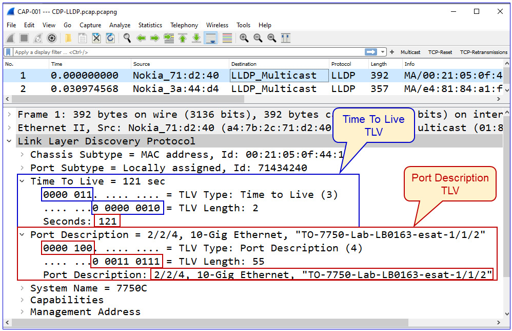
Figure 10.7 – TLVs
Here, we see the following:
- The first TLV is the 0000 011 type, 3 as a decimal, and 0 0000 0010 in length, which is 2 as a decimal, to note the correct value of 2 bytes in length. The value is 121.
- The second TLV is the 0000 100 type, 4 as a decimal, and 0 0011 0111 in length, which is 55 as a decimal, to note a value of 55 bytes in length. The value is a text field with the name of the interface.
In LLDP, the Type field is 7 bits, and the Length field is 9 bits. These lengths can be different on other protocols.
Attacks on a VLAN mechanism and VLAN flooding
There are several ways a switch VLAN can be attacked. The first and the simplest one is a MAC flooding attack in which we overrun the CAM table of the LAN switch so that the switch cannot learn new and real MAC addresses. We talked about this attack in Chapter 6, Finding Network-Based Attacks, in the L2-based attacks section.
The second type of attack is based on faking inputs that the switch expects – in this case, inputs on port status. Here, we focus on the mode of operation of a switch port. Let's see how it works.
A switch port can work in several states:
- Access mode – in this mode, the connected switch port is configured to participate in a single VLAN. The configuration command for this mode is switchport mode access in Cisco, interface-mode access in Juniper, and port link-type access in HPE.
- Trunk mode – in this mode, the port is used by multiple VLANs. This mode is usually used between switches or between a switch and another networking device. The configuration command for this mode is switchport mode trunk in Cisco, interface-mode trunk in Juniper, and port link-type trunk in HPE.
- Automatic modes – in this mode, the port is configured to adjust itself to the configuration. In Cisco, for example, we have switchport mode dynamic desirable or switchport mode dynamic auto; in both, the configured port becomes a trunk by the specific conditions of the port connected to it.
Important Note
While configuring networking devices, we have used examples from leading vendors – Cisco, Juniper, HPE, Extreme Networks, and so on. There are, of course, many other vendors, but we cannot use examples from all of them, and as you have seen by now, the commands are quite similar. In any case, we have provided the guidelines, and it is strongly recommended to use user and configuration manuals before making any changes to your network.
The point in sending fake packets to a switch is to use protocols that are used by the switch to change its configuration. We can see this in Figure 10.8:

Figure 10.8 – DTP and VLAN hopping
As we can see in the figure, before sending fake Dynamic Trunking Protocol (DTP) frames to the switch, the laptop is connected to a standard port that is configured in one of the dynamic modes we mentioned earlier. In this scenario, when a broadcast packet is sent from the sixth PC to the network, it will not arrive at it.
Important Note
DTP is a proprietary protocol from Cisco that has not been standardized. Similar protocols are Huawei's Link-type Negotiation Protocol (LNP), and there are some vendors that do not support this feature.
When we send a fake DTP frame to the switch, in the format shown in Figure 10.9, the port that the laptop is connected to will automatically be changed to the Trunk port, and broadcast packets sent from the sixth PC will arrive at it; the laptop will discover the existence of the sixth PC and be able to read information from it:
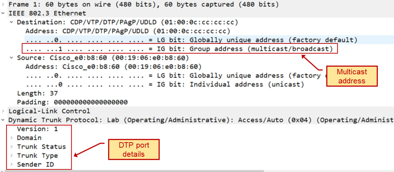
Figure 10.9 – The DTP frame
To perform a VLAN hopping attack, we can use a captured DTP frame (collected from previous captures or downloaded from cases on the internet), change Trunk Status and Trunk Type, and try to gather information from the switch.
To protect against VLAN hopping attacks, use the simplest rule in the book – do not auto-negotiate and do not let the switch decide. Configure each port with a fixed role – it should be either the access port or the trunk port.
Let's now go one layer up to Open Systems Interconnection (OSI) layer 3 and discuss the various types of ICMP-based attacks.
ICMP-based attacks, ping scans, the ping of death, and L3 DDoS
IP-based attacks are attacks that focus on layer 3, which is everything related to IP addresses. ARP-based attacks focus on a network device's ARP cache, usually to hijack end-to-end sessions by impersonating the addresses of the target of the attack. We talked about these two types of attacks in Chapter 6, Finding Network-Based Attacks, in the L3 and ARP-based attacks section.
In this section, we will talk about the following attacks:
- Ping scans and layer 3 DDoS
- The ping of death and malformed packets
Let's get to the details.
Ping scans and L3 DDoS
Ping scans can be used for two purposes:
- For network discovery, to identify potential victims
- As a DDoS attack, using ICMP packets to block a network or for loading network devices
A ping scan used for network discovery
For network scanning, we will simply see a scanning pattern from a single source. It will start with an ARP scan, to discover network devices that respond to ARP requests. We can see this in the next figure:

Figure 10.10 – An ARP scan
After the ARP scan, the scanner – in this case, a piece of software named Angry IP Scanner – will start to send ICMP requests and potentially receive ICMP responses from discovered devices.
Important Note
It can be that a device responds to an ARP request but not to an ICMP request – this usually happens because the ICMP is blocked by a firewall on the end device while ARP is still responding.
In Figure 10.11, we can see the statistics – the Conversations table from Wireshark. On the left, we can see that 192.168.1.136 sends pings to the devices that responded to ARP requests. On the right, we can see that three ICMP packets are sent to the destinations, while 192.168.1.142 does not respond (marked 1) but all the others do (2, 3, 4, and 5):

Figure 10.11 – The ping scan results
The only thing we have to make sure of is that we know who the sender is – for example, a management system that uses ping discovery and not an intruder that scans the network for vulnerable devices.
Let's see the second type of ping scan, the one that is used for DDoS.
A ping DDoS attack
As we learned before, DDoS is a type of attack that prevents users from accessing a network or the services connected to it. When sent in large quantities, a ping can do this. Let's see Figure 10.12:

Figure 10.12 – A ping worm example
In the packets window, we can see a pattern of scanning – 192.168.110.57 finishes scanning the 192.168.8.0-255 address range and then starts to scan the 192.168.9.0-255 address space. On the right side of the Wireshark I/O graph, we can see a straight line indicating a fixed bandwidth consumption of 800,000 bits per second. Knowing that the line is an 800,000-bits-per-second line and no other traffic is sent brings us to the conclusion that the communications line is blocked.
The ping of death and malformed packets
The ping of death is quite an old type of DDoS attack. Most of the systems produced since the early 2000s protect against it by default. The principle here is simple – the attacker sends ICMP packets greater than the maximum allowed packet size, 65,535 bytes long, that some old TCP/IP-based protocol stacks were not designed to handle, making them vulnerable to packets above that size.
Important Note
When using old or slow devices, pings or large IP packets can also cause servers to slow down to the point of misfunctioning, even in the case of regular operations and not necessarily attacks. This can happen when a sender application sends large packets over TCP or UDP that go down to the IP layer, which fragments them into several smaller sized 1,514-byte Ethernet frames. When the destination is an old or slow device, this alone can cause it to crash.
In the next section, we see some attacks related to fragmentation.
IP fragmentation and teardrop attacks
Unlike the ping of death in which we send packets larger than the legitimate IP packet size, fragmentation attacks send legitimately sized IP packets – that is, packets smaller than 65,535 bytes. The purpose of this type of attack is to target slow end nodes so that the reassembly of these fragments into a single large packet will slow down the target to the point of misfunctioning.
In teardrop attacks, we send fragments with the wrong offset values in the IP header, causing old TCP/IP stacks to crash. These types of attacks are not common, and the majority of operating systems since the early 2000s protect against them.
Performing fragmentation attacks is simple. Use tools such as the following:
- A simple ping command with the -l option <number of bytes> to send large ICMP packets to the destination
- Tools such Colasoft Packet Builder, in which we can create our own packets and send them
- Any packet generation tool such as iPerf, JPerf, Nmap, or any tool that can generate large TCP, UDP, or IP packets
In the next section, we will go up to layer 4, learning about some smarter and more dangerous attacks.
Layer 4 TCP and UDP attacks
We talked about TCP and UDP in Chapter 2, Network Protocol Structures and Operations, in the L4 protocols: UDP, TCP, and QUIC section. In this section, we will drill down to protocol details and learn about potential attacks and how to protect against them.
We will learn about various types of scans – SYN scans, ACK scans, reset scans, Windows scan, and so on. We will mostly use the Nmap tool, available in the Command-line Interface (CLI) and graphical implementation for Windows and Linux.
UDP flooding attacks
As we saw in Chapter 2, Network Protocol Structures and Operations, in the L4 protocols: UDP, TCP, and QUIC section, UDP is quite a simple protocol, with a simple header – source port, destination port, message length, and message checksum.
As such, there are simple attacks that can be performed with UDP, with simple measures we can take against them. You can use several basic UDP attacks:
- nmap -sU <target-device> for UDP scanning in order to find open ports on the target device
- Flooding tools such as Colasoft Packet Builder for traffic generation
To protect against UDP-based attacks, use standard-rate limit commands and firewalls to enable only allowed services over UDP (mostly Domain Name System (DNS) and Session Initiation Protocol (SIP)/Real-Time Transport Protocol (RTP)).
SYN flooding and stealth scan attacks and countermeasures
As we saw in Chapter 2, Network Protocol Structures and Operations, in the TCP connectivity and reliability mechanisms section, the sender – that is, the device that initiates the TCP connection – uses the SYN flag as a request to open a connection, the receiver answers with SYN-ACK, the sender answers with ACK, and the connection is opened. In a SYN flood attack, the attacker sends multiple SYN requests to the receiver, causing it to allocate a memory buffer to the expected connection. This way, the receiver allocates additional resources for every SYN request, to the point that no new connections can be made, ultimately resulting in the inability of the server to fulfill its function.
How to generate TCP SYN attacks
First, it is important to distinguish between SYN scans and SYN attacks. In SYN scans, the attacker scans for open TCP ports on the target to find open ports that can be attacked. In SYN attacks, the attacker uses the open ports to cause the target to stop functioning. Although a SYN scan is not targeting the victim's resources, it can, as we can see in the next example, also cause degradation in the victim's performance.
Let's see first how to scan for open ports and then how to target them with SYN attacks.
In the following figure, you can see how the nmap command is used to SYN-flood a Cisco Catalyst 2960 series of switch, using the nmap -sS -T5 -v 172.30.0.241 tee command, broken down as follows:
- -sS – used for the SYN scan
- -T5 – the aggressive timing template (0–5, where 0 is the lowest rate and 5 is the highest)
- -v – verbose:

Figure 10.13 – Configuring Nmap for the SYN scan
We generated 1269 TCP SYN packets in 3.55 seconds, discovering the open ports 22, 23, 80, and 443. In the next figure, we can see the result on the switch under a scan:

Figure 10.14 – The SYN attack's influence on the LAN switch CPU
We see that CPU utilization rose up to 60% at the time of the attack – that is, for a few seconds. If there are multiple attacks, without the right protection, it can easily crash the switch or the other communications equipment under attack.
To generate the TCP SYN attack, we can use the Kali Linux hping3 command. Let's see how it's done.
First, install hping3:
- Change to Kali superuser mode:
$ sudo su
- Install hping:
# sudo apt-get install hping3
- Use the following command:
hping3 -c <number of packets to send> -d <packet size> -S -w <TCP Window Size> -p <destination port number> --flood --rand-source <attacked address>
You see an example in the following Figure 10.15:
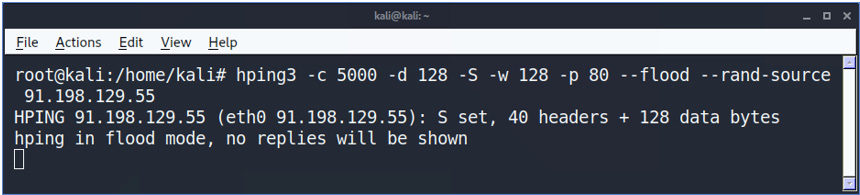
Figure 10.15 – The hping command
In the command, we are sending 1,500 packets (-c 5000) at a size of 128 bytes (-d 128) each, with the SYN flag (-S) enabled, and the TCP window size is 128 bytes (-w 128). To direct the attack to the victim's web server, we specify port 80 (-p 80) and use the --flood flag to send packets at an aggressive packet rate. The --rand-source flag generates random IP addresses to hide the real source, avoid detection, and prevent the victim's SYN-ACK reply packets from reaching back to the attacker.
How to discover TCP SYN attacks
Discovering TCP attacks can be performed in several ways, depending on the severity of the attack. First, we can always use Wireshark or other packet-discovery tools. Keep in mind that there is a difference between SYN scanning and SYN attacks. SYN scanning runs on different TCP destination ports trying to find an open port, while SYN attacks are targeting the end device with the TCP SYNs trying to crash it. Blocking TCP scans is a basic feature that is covered by a firewall's default configuration, while TCP SYN attack protection is covered by intrusion detection mechanisms and usually must be activated only when under attack.
Discovering SYN attacks can be performed with Wireshark or other packet analyzers, or with firewall and security devices that look inside the packets passing them. When using Wireshark, you will see the following:

Figure 10.16 – The hping command results in Wireshark
In the capture file, we can see a capture of the hping command executed in Figure 10.15. We can see SYN packets sent from random addresses, all of them to port 80 at the destination address. In the Time column, we can see time differences of tens of microseconds between them – an indication of an aggressive attack.
How to protect against TCP SYN attacks
In Chapter 7, Detecting Device-Based Attacks, in the SYN-scan and attacks targeting the management plane processes availability section, we talked about SYN attacks targeting communication devices. Here, I want to say a few words about how to filter these attacks before they cause any damage. There are various mechanisms for this, coming from various vendors, and it was even standardized by the Internet Engineering Task Force (IETF) in 2007 with RFC 4987 – TCP SYN Flooding Attacks and Common Mitigations.
There are two cases when we need to protect devices against SYN flooding DDoS attacks. The first one is when the devices are behind a firewall, and the second is when the device is facing the internet directly or located in an internal network without firewall protection. Let's talk about them.
When a device is behind a firewall, we count on the firewall to provide protection against SYN flooding. Every firewall from every vendor has its protection mechanisms. Some common mechanisms are as follows:
- Using thresholds for the number of SYNs per second
- Using a proxy mechanism, constantly or above a pre-defined threshold, when the proxy sends a SYN-ACK to the source and forwards the connection only if an ACK is received
- Using behavior analytics to check for a sudden increase of traffic from a specific interface (usually used within Internet Service Provider (ISP) networks before getting to the customer's site)
- Decreasing the time-wait in which we keep resources open waiting for the SYN-ACK to arrive
You can read about additional mechanisms on each vendor's websites, including the following:
- On Check Point, it is explained here: https://sc1.checkpoint.com/documents/R81/WebAdminGuides/EN/CP_R81_PerformanceTuning_AdminGuide/Topics-PTG/SecureXL-Accelerated-SYN-Defender.htm#:~:text=The%20Check%20Point%20Accelerated%20SYN,suspected%20TCP%20SYN%20Flood%20attack.
- On Palo Alto Networks, it is explained here: https://docs.paloaltonetworks.com/pan-os/10-1/pan-os-web-interface-help/network/network-network-profiles/network-network-profiles-zone-protection/flood-protection.html.
- On Juniper Networks, it is explained here: https://www.juniper.net/documentation/us/en/software/junos/denial-of-service/topics/topic-map/security-network-dos-attack.html#id-understanding-syn-cookie-protection.
For devices facing the internet or devices that are not protected by firewalls and still subject to attacks, there are some measures we can take to protect them:
- Use Access Control Lists (ACLs) to limit the source addresses from which access is allowed to the device control and management planes.
- Decrease the timeout for completing the three-way handshake of a TCP connection.
- Limit the amount of connection requests coming into the device.
For example, by using ACLs, you can allow only addresses coming from 192.168.1.0/24 and 192.168.2.0/24 from the GigabitEthernet 0/1 interface (a Cisco configuration example):
access-list 120 permit ip 192.168.1.0 0.0.0.255 any
access-list 120 permit ip 192.168.2.0 0.0.0.255 any
access-list 120 deny ip any any log
interface GigabitEthernet 0/1
ip access-group 120 in
On Cisco devices, to decrease the timeout for a TCP three-way handshake, you can use a couple of features:
- A connection limit feature
- Dead Connection Detection (DCD)
You can read more about both here: https://www.cisco.com/c/en/us/td/docs/security/asa/asa72/configuration/guide/conf_gd/protect.html.
On Juniper Networks devices, enable syn-flood-protection-mode. You can read more about it here: https://www.juniper.net/documentation/us/en/software/junos/flow-packet-processing/topics/ref/statement/security-edit-syn-flood-protection-mode.html.
Now that we have talked about SYN attacks, let's talk about other TCP flags and flag combinations that can be used for attacking network devices.
TCP RST (reset) and FIN attacks
As we saw in Chapter 2, Network Protocol Structures and Operations, in the section on TCP packet structure, the two ways to close a TCP connection are by using the FIN or RST flags. The first way is with the TCP-FIN (finish) flag, as we can see in Figure 10.17:

Figure 10.17 – TCP connection termination with FIN
In the figure, we can see the following:
- The client sends a packet with a FIN flag (FIN-WAIT-1), telling the server that the client has finished sending data to the server.
- The server sends an ACK, confirming the acceptance of the FIN.
- After a while, when the server has nothing more to send, the server sends a FIN to the client.
- The client confirms the acceptance of the FIN with an ACK, and the connection is closed.
Closing a connection can be initiated by both sides, not necessarily the client. A TCP-FIN attack will try to interfere with real connections – for example, by sending a FIN frame to one of the sides, faking the source IP address of one of the sides.
A TCP reset, using the TCP-RST flag, is used in two cases. The first case is in an ordinary operation – for example, you browse a web page that finished sending the data to you, so it sends you a reset for a fast connection close. The other case is when something goes wrong, so the side of the connection that discovers it sends the reset.
For generating an RST or FIN attack, we must interfere with the ordinary operation of a TCP connection, described in Chapter 2, Network Protocol Structures and Operations, in the L4 protocols: UDP, TCP, and QUIC section. Interfering with a connection can be done by sending TCP packets with an IP address and TCP port number of one of the sides, with FIN or RST flags, or with wrong sequence numbers that will cause the accepting side to send a reset (which is sent when something goes wrong) and close the connection.
In both cases, the purpose of the attack is to generate packets and to send them to one of the sides, as it will close the good TCP connections that it is using. Let's see how we can generate these attacks.
How to generate TCP RST and FIN attacks
The principle of TCP RST and FIN attacks is to impersonate a part of a real TCP connection, and when doing so, to send an RST or FIN to one of the sides, telling it to close the connection. To do so, we first need to know the connection details, including the end IP addresses and TCP port numbers. Achieving this information can be done in three ways:
- Eavesdropping on the connection between the two ends of the connection
- Capturing data on one of the two ends of the connection
- Smart guessing – for example, an attack on port 80 on a web server, with spoofed source IP addresses
We talked about the first option in Chapter 2, Network Protocol Structures and Operations, in the Layer 2 protocols: STP, VLANs, and security methods section, and will talk about it in Chapter 12, Attacking Routing Protocols, in the Potential threats and common attacks section.
Capturing data can be done on one of the sides, the client or the server. Our book is about risks and attacks on data networks, so end nodes are out of the scope of it.
The third way, smart guessing, is more difficult but can bring results with a little patience. Let's use an example in which we have a 172.30.0.0/24 network that we are connected to, locally or remotely. As we saw in Chapter 6, Finding Network-Based Attacks, in the Reconnaissance and information gathering section, listening to the network gives us a lot of information. Let's see what we have in Figure 10.18. Since we can simply connect to a switch port, we will see only broadcasts and, in some cases, also multicasts:

Figure 10.18 – Network reconnaissance
By now, we know that we have a server, 172.30.0.11, that advertises in NetBIOS, which is a SQL server. If we Google SQL port numbers, we can see that SQL Server usually uses TCP port 1433.
Now, we know that we have a SQL server with a 172.30.0.11 IP address that listens to TCP port 1433, and requests are coming to it from clients on 172.30.0.0/24 to cut off TCP connections, so we can generate one of two attacks:
- Generate RST or FIN packets from a source address on 172.30.0.X (X from 1 to 254), with a random source port, to 172.30.0.11 port 1433.
- Generate RST or FIN packets from 172.20.0.11 port 1433 to PCs on 172.30.0.X (X from 1 to 254) on random sequence numbers.
There are several tools that can be used in order to perform these attacks. In Scapy, for example, you can send this command:
srloop(IP(dst="172.30.0.11")/TCP(dport=RandNum(1024,65536),flags="R"))
The can be broken down as follows:
- 172.30.0.11 is the target – that is, the device under attack.
- dport=RandNum(1,65536) is a random destination port.
- flags="R" is a reset flag.
The following is a good reference website to learn more about the Scapy command: https://scapy.readthedocs.io/en/latest/usage.html.
In Figure 10.19, you can see the capture of the packets that are sent to the device under attack:

Figure 10.19 – The reset attack
In this scan, we can see TCP packets with the reset (RST) flag turned on sent to 172.30.0.11, to random destination ports. We can change additional parameters in Scapy and get better results. Replacing the R TCP flag with F will generate FIN attacks.
Now, let's see how to discover these scans.
How to discover and protect against TCP RST and FIN attacks
There are several ways to discover FIN and RST attacks. First, as we can see from Figure 10.19, packet capture will show it immediately. Check whether you see too many resets coming from the same source, scanning patterns, simultaneous FIN packets, and so on.
Second, most firewalls and IDS/IPS systems discover these types of attacks. Use the Network Access Control (NAC) system to block any unauthorized access to a network, and follow communications equipment hardening procedures.
Now, let's see some additional attack types that involve the use of various TCP flags.
Various TCP flag combination attacks
There are many names for TCP-based attacks – ACK scans, FIN scans, Null scans, and Xmas scans. What is common to most of them is the use of a combination of TCP flags to confuse a communications device.
How to generate TCP flag combination attacks
Let's look at the next example. What we do is as follows:
- Generate a SYN attack with nmap, as we saw in the previous section.
- Capture the packets with Wireshark and filter out TCP SYN packets. We do this with the tcp.flags.syn==1 display filter. You can see how to do it in Chapter 8, Network Traffic Analysis and Eavesdropping.
- Export the displayed packets to a file.
- Open Colasoft Packet Builder and use Import to import the file you exported from Wireshark. In the following figure, you can see what you will get:

Figure 10.20 – Using Packet Builder for a TCP attack
- Change the TCP flags. I used the craziest combination I could think of – ECN for congestion notification, URG for urgent pointer (no one ever used this flag), PSH for push, and SYN for sync. There is no possibility that a combination like this will really be sent.
- Click on the Send button in the main menu. You can see how to do this in Chapter 6, Finding Network-Based Attacks, in the STP/RSTP/MST attacks section.
- The result, using the show proc cpu history command on a Cisco IOS device, was 90% utilization of the switch CPU.
Now that we have seen ways to generate TCP flag attacks, let's see how to protect against them.
How to identify TCP flag combination attacks
There are several ways to identify TCP flag combination attacks, some of which are unique and some of which will be the same for other types of attacks. In Figure 10.21, we can see what happens to an unprotected device CPU under this type of attack. It's important to note that in CPU load values of over 90%, as we can see here (the exact number is presented at the top of the graph), the device CPU will surely slow down, while upon reaching close to 100%, it will start to drop packets and stop functioning:

Figure 10.21 – Multiple TCP flag attack results
Since we have attacked the CPU and caused degradation in device performance, these attacks are considered to be a type of DDoS attack, and as such, they can be identified and blocked in several ways. The first thing we need to do is to identify the attack, and the second thing is to block it. Let's see how to do it.
Identifying flag attacks can be done in two ways – by detecting a sudden increase of traffic and identifying irregularities in TCP packets.
Detecting a sudden increase in traffic can be done with standard tools such as SNMP base tools and NetFlow/IPFIX tools (see the NetFlow and IPFIX section in Chapter 9, Using Behavior Analysis and Anomaly Detection).
In Figure 10.22, we can see an example of DDoS discovery. The graph is from the freeware version of Paessler Router Traffic Grapher (PRTG) (up to 100 sensors), showing the inward and outward traffic on a router interface. We can see that there is an increase in traffic from 30–40 Kbps to 1,000–2,000 Kbps of outward/inward traffic in bits per second – that is, 1 Mbps for traffic going out of the interface and 2 Mbps for traffic coming into the interface:

Figure 10.22 – A sudden increase in traffic
The interface that was monitored was a router interface attached to the company's firewall, as we can see in Figure 10.23. In the figure, we can see the company's network (a part that is relevant to our case):

Figure 10.23 – The company's network under DDoS
As we can see from Figure 10.23, we have 2 Mbps coming into the interface and 1 Mbps going out of the interface – which is most of the traffic coming from the HQ (headquarters) on the left.
Now, values of 1 Mbps/2 Mbps are still low and should not usually worry us, but if we look at the next graph in Figure 10.24, we can see that the CPU load goes up to 60% for the duration of the peak in the traffic:

Figure 10.24 – The CPU load
Since regular data passing through the router should not load the router CPU (with load of traffic no more than 1–2 Mbps), we can figure out that this is traffic targeting the router management or control planes. This can be referred to as a strong irregularity.
How to protect against TCP flag attacks
To block irregular TCP flag combinations, we can configure our devices as follows.
For Cisco devices, configure ACLs by allowing TCP packets only if the TCP flags are within any of the regularly allowed combinations:
ip access-list extended example1
permit tcp any any match-all +syn
permit tcp any any match-all +ack +syn
permit tcp any any match-all +fin
permit tcp any any match-all +fin +ack
permit tcp any any match-all +rst
permit tcp any any match-all +rst +ack
permit tcp any any match-all +psh
permit tcp any any match-all +psh +ack
end
Match all the permits flag combinations that are identical to the command line – for example, +syn allows packets with the SYN flag only.
For other vendors, in some cases, the TCP checks are performed automatically (usually in firewalls). Check the vendors' manuals for additional information.
In this section and in the previous one, we saw two types of DDoS attacks – TCP SYN attacks and TCP flag manipulation attacks, attacks that are usually used to overwhelm the victim's resources to the point of misfunctioning. In the next section, we will talk about another common attack – TCP session hijacking – that is, to steal sessions and the information inside them.
TCP sequence attacks and session hijacking attacks
TCP sequence attacks, also referred to as TCP session hijacking, refer to a case in which we intercept a conversation between two ends of a connection and impersonate one of the two ends. This is one of many types of man-in-the-middle attacks, when we intercept data between two communicating devices.
To run the TCP session hijacking attacks, we will use Scapy – a packet manipulation tool written in Python. Scapy can be used to capture, decode, fake, and send packets.
To install Scapy on Windows, do the following:
- Install Python version 3.4 or higher.
- Install the npcap driver (if you have followed along with this book up to this chapter, you should have it installed by now).
- Open cmd and run pip3 install scapy.
To install Scapy for Linux (Ubuntu or Kali), run the following commands:
- sudo apt update
- sudo apt install python3-scapy
In the following example, we sent a simple packet with Scapy, and in the next one, we can see how it looks in Wireshark:

Figure 10.25 – Sending packets with Scapy
In Figure 10.26, you can see the packets:

Figure 10.26 – Scapy-generated packets
To send malformed packets, use the following:
send(IP(dst="100.1.2.3", ihl=2, version=3)/ICMP())
Here, ihl indicates the internet header length.
In the next example, shown in Figure 10.27, we can see the TCP SYN scan sent to www.ndi.co.il, from which we got 11 answers. In the Wireshark capture, we can see the answer to port 21 – it appears that port 21 is open and is sending us a SYN-ACK back, and Scapy answers with a TCP reset to close the connection:
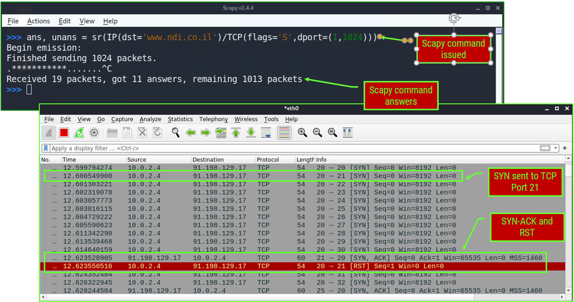
Figure 10.27 – TCP port scanning with Scapy
Now, let's see how to hijack the TPC sessions. Write the following command to collect answers from the destination:

Figure 10.28 – Scapy collecting the sequence numbers
We get the answers as follows:

Figure 10.29 – The sequence numbers
For more information on Scapy, you can refer to https://scapy.readthedocs.io/en/latest/usage.html, https://santanderglobaltech.com/en/guide-using-scapy-with-python/, and many other websites.
To hijack real sessions, we need to perform a man-in-the-middle attack. We will return to this in the application chapters.
Summary
In this chapter, we talked about network protocols – from Ethernet and MAC addresses, through ARPs and IP addresses, to higher layers with TCP and UDP, talking about potential attacks against them, how to generate attacks, and how to protect against them. We learned how to generate ping attacks, TCP SYN, and various flag attacks, how to discover them when they happen, and how to protect against them, and we finished with TCP hijacking attacks – how they are implemented and how to protect against them.
In the next chapters, we will start to get into the details of various network operations and application protocols, starting with wireless networks.
Questions
- Using the macof -i <interface-name> command – for example, macof -i eth0 – will influence which of the following?
a) The LAN switch you are connected to
b) The entire LAN in layer 2 only
c) The entire LAN, including switches and routers
d) The entire organization networks
- Ping scans are dangerous for what reason?
a) They load the network.
b) They discover network elements that can be attacked upon discovery
c) They can be used as a DDoS attack.
d) All of the above.
- What is the difference between a SYN scan and a SYN attack?
a) SYN scans and SYN attacks are both used for attacking network resources.
b) A SYN scan discovers network devices while a SYN attack discovers open TCP ports.
c) SYN scans are used to discover open ports while SYN attacks are used to attack network devices.
d) All the these.
- The hping3 -c 10000 -d 128 -S -w 1024 -p 80 --flood --rand-source 1.2.3.4 command is used to do what?
a) Generate an attack with 10,000 packets on random destination ports.
b) Generate an attack on port 80 with random source ports.
c) Generate an attack with random source IP addresses on port 80 on server 1.2.3.4.
d) Scan the network for a device that answers to port 80 – that is, the HTTP server.
- TCP flag combination attacks on a networking device are used for what?
a) To load the control and management planes and bring a device to CPU and memory load, which can interfere with the normal behavior of the device
b) To cause a load on a device's data plane, causing the device to drop the packets due to interface loads
c) To prevent access to a device from management systems used to control it
d) As a type of malware to disable an endpoint connected to a remote communication device