
What Differentiates Logical and Physical Topologies?
Computer networks are arranged in a manner that includes the way each is physically connected, which is the physical topology (wired or via the air if wireless), and the logical manner, which pertains to how resources are segregated and allocated. All computer networks have physical and logical topologies, and it is possible for the topologies to be similar. From the user perspective, neither topology matters unless the user is unable to access the resources needed to complete tasks.
Because it is easiest to consider a topology as the way computers and devices are connected, let’s cover wired topologies first. Wired topologies have a physical wire between devices, allowing for communication among those devices. A route is the pathway that communication packets travel within the wired connections of a network. The route for network communication is not always easily identified or managed if there is not appropriate documentation to aid the network administrator or engineer. Network equipment, including routers, switches, and gateways, may alter what appears to be a straightforward path of communication to better balance the communication load or to restrict access to certain devices or parts of the network.
The logical topology is how the network appears from any device or user and is governed more by policy and access than by physical connectivity. Instead of how the computers and components are physically arranged, think of the logical topology as how those computers access and share data and resources. It may have little resemblance to the physical connectivity of the devices.
Whether identifying the physical or logical topology, some elements should be kept in mind. Due care should be exercised when planning a network installation or upgrade, or scaling (whether making it bigger or smaller) to ensure that the appropriate physical and logical topologies are selected to support the needs of the business. Both topologies should be documented clearly in both the security policy and in a standalone network document, so it is accessible for troubleshooting networking problems by the network administrators and engineers.
Types of Physical Topologies
A bus topology is considered a linear network because it has computers in a line (although not necessarily a straight line). See FIGURE 3-9. Each computer or device in the topology is connected to the computer or device that is next in line. The actual configuration could be wavy (weaving up and down rows of computers in an office space) or appear circular in formation, although it is not a ring or circle, as the ends never meet. A bus topology requires equipment called terminators to be placed at each end of the physical cable. The terminators stop the signal on the line from bouncing back and forth down the line.
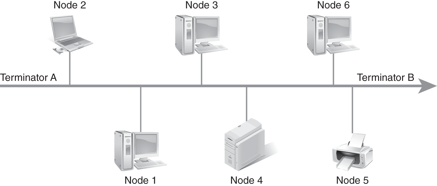
FIGURE 3-9 A bus topology.
In this topology, a single cable is used as the backbone of the network. The computers and devices that are part of that network are connected to that cable. This network topology is easier to implement and troubleshoot in home office and small business settings, but it is often slower, especially when there are more than 10 devices on that network. When a system fails in a bus topology, the entire network goes down.
Connectivity issues in the network affect all other computers and devices connected to the network in a bus configuration. A network with a bus topology is often more susceptible to performance issues as the number of computers and devices on the network increases beyond 10. There are also length limitations on the cabling—the signal degrades the further from the origination point the packet gets. Repeaters often solve some of the problems with long distances, but if the desired quality of throughput is not achieved, wireless may be added to reach additional distances. However, wiring and installation is easier and usually less expensive than other configurations, which is why the bus topology is the most common network design in small office/home office installations. Another advantage of the bus network is the relative ease of scaling the network up to the maximum number of devices or removing devices to scale down.
The ring topology uses a cabling scheme that is closed; that is, it connects one end of the cable/network to the other end to form a ring (see FIGURE 3-10). Each computer or device is connected to two devices, one on each side. This topology requires a special packet called a token, similar to a “speaking baton” in childhood games where only the person in possession of the baton may communicate. The use of a token is the reason this topology is often referred to as “token ring.” Because this network scheme uses a token to control access to the network cable for communication and transmission, it has fewer problems with data collisions than other physical topologies; however, it will still experience slower speeds when multiple devices on the network attempt to communicate at the same time. Ring networks often use repeaters when there are a large number of nodes on the network.
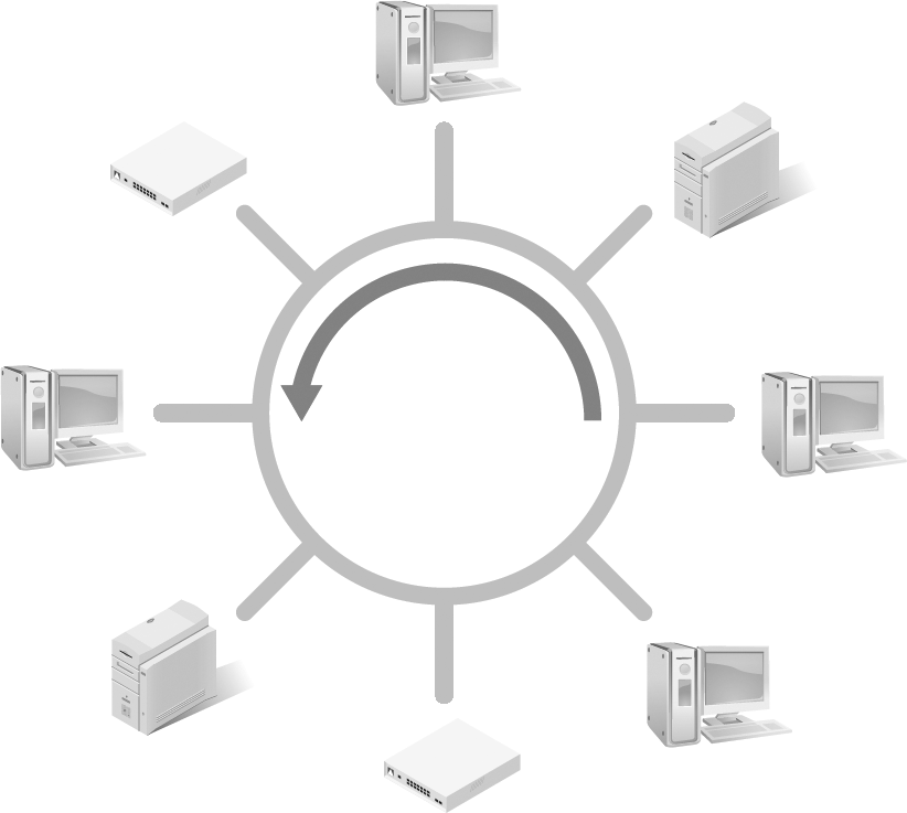
FIGURE 3-10 A ring topology.
If the ring network is unidirectional, which means the token moves in only one direction around the ring, there could be delays. Every computer and device on the network is polled (asked or queried) if it has packets to send before the token moves to the next device, in order, around the ring.
A bidirectional ring requires two connections to each device and provides redundancy not available in a unidirectional token ring network. This type of ring has an entire cabling setup for a token to go in either direction. That means it is not actually a bidirectional ring; it is two separate rings, each going in a separate direction.
Essentially, the ring network is implemented twice with flow in opposite directions. The wait time is not necessarily cut in half due to the addition of the second network, but it is a faster communication system than a single ring. Cost is a deterrent for many types of ring networks, and troubleshooting is more complicated because the administrator must first determine which network is experiencing the problem.
Benefits of a bidirectional ring include redundancy because of the duplication of the entire network. However, if a computer goes down, it is possible the entire network could go down in both directions. Speed is potentially improved, due to load balancing across the two ring networks, but if the network is at capacity, it would still seem slow to users. The token is also not directly opposite on each network. Tokens work through a polling process. Each device is polled to identify if there are communication packets to send across the network. If not, the token moves to the next device in the ring. If there are packets to send, the device sends those packets, and the token moves to the next device in order. Depending on how much data is sent, the system could run slower than anticipated.
The star topology, shown in FIGURE 3-11, provides a layer of performance protection that is not present in the bus or ring topologies. The network design has an independent cable to each device. This configuration often uses much more cabling than a bus or ring topology, but it benefits from exclusive use of each cabling segment. If one segment is disrupted, it usually does not bring down the entire network. Because the cable to each device is isolated from other devices, it offers redundancy from element breakage. But it does not offer full redundancy to all devices, as the affected device will not have connectivity to the network until the issue is resolved.
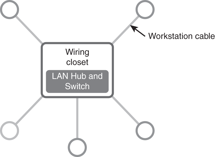
FIGURE 3-11 A star topology.
A common visual for this design is a circle with a line emanating from the center to devices on all sides. This makes the image resemble the spokes in a wheel or outlined pieces from a pie. In application, the “spokes” do not need to extend to all sides. It is common to have the shape appear more like a squid where the server and hub are at the top and tentacle-like cables drop down to each device. Either way, the inclusion of a central “hub” and segregated cables to each device identifies the topology, even if the physical design bears little resemblance to an asterisk. The star topology is more fault-tolerant than the bus topology, as the independence of each wired line allows for one or more devices to lose connectivity; the remaining devices maintain connectivity to the rest of the network.
Mesh topology is the most redundant of the wired topologies, as the design provides isolation for devices and redundancy in the event that a segment of the network no longer functions to allow communication through. Mesh topologies can be enacted in two forms: full and partial connections. In a full connection mesh network (FIGURE 3-12), all devices are connected to all other devices. This essentially means that before every device on the network is a hub to facilitate and streamline the connections.
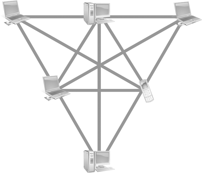
FIGURE 3-12 A full mesh topology.
A more common and less cost-intensive method is the partial connection mesh (FIGURE 3-13), where all high-demand, resource-intensive devices have redundant connections, but not every device to every other device. In this type of application of the mesh topology, there is redundancy for all servers and the main systems in each area. For example, in a school that offers online courses, the main servers would have redundant lines between each, and the online learning management system (LMS) that hosts the online class environment would have cables to several other servers and devices. If one path to the Internet was inaccessible, there would be others, so the classroom environment would still be available to students. This is common in mission-critical areas of a business and in the military, as communication is essential to survival.
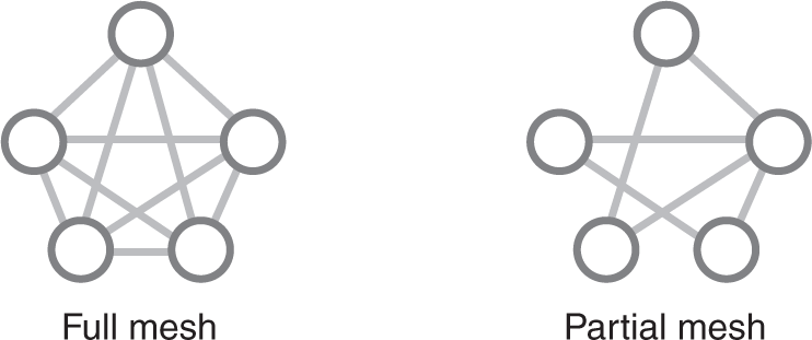
FIGURE 3-13 A partial mesh topology compared to a full mesh topology.
Wireless topology is a bit of a misnomer. In a wireless installation there is very little wire, as the devices connect using the air as the medium of exchange for communication packets. Some wiring may exist in areas that require additional redundancy, so that wired and wireless provide that alternative in the event that one method fails to function properly. There is at least one wireless router in a wireless network topology. This is the connectivity point that allows for interconnection and access to the Internet. See FIGURE 3-14.
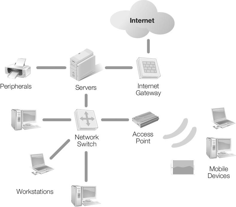
FIGURE 3-14 A wireless network topology.
Logical Topology
All of networking is the communications between devices, but logical networking is more about connections and permissions than arrangement. In a typical office environment, workers may be able to see each other as they work because the desks in the work area are in close proximity. The computers, however, may not be able to detect the existence of the other computers and devices. Implementation of a logical network is important for separation of duties and access. Usually, the employee responsible for marketing an organization’s products or services is not the same person who completes the organization’s payroll or pays the bills. Those job functions are usually completed by two or more people who would not typically access the same programs and tools. An example of a logical topology is shown in FIGURE 3-15.
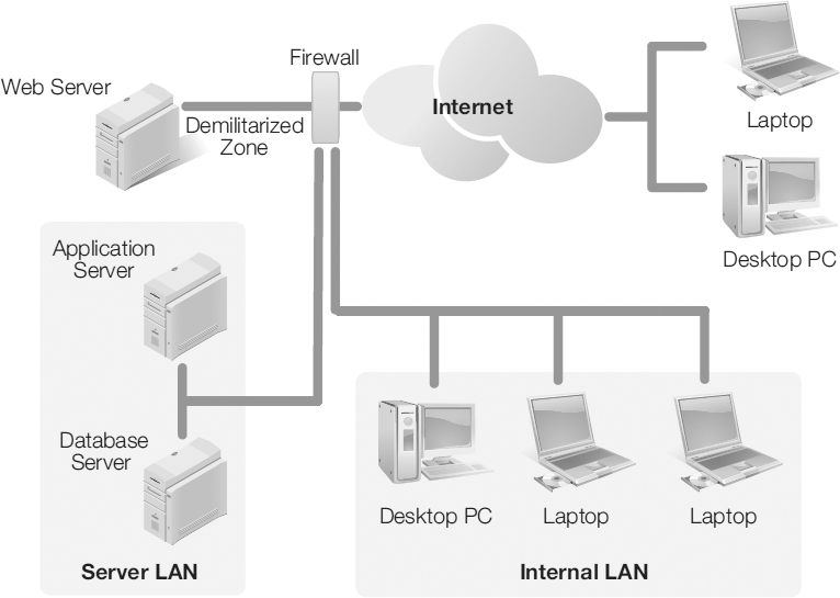
FIGURE 3-15 A logical topology.
For those tools that the entire company needs to access, such as email, all employees should be granted access. For the other resources, like payroll applications or inventory management, only those employees with job responsibilities requiring access to those programs are granted access to those systems. If there are several employees in each department or division, access could be granted through the use of a template or group.
Logical networks limit access to data and resources by allowing only those individuals and devices that require such access, if the network is set up correctly. This segmentation protects employees from accidentally accessing, altering, or deleting information. Segmentation aids in legal compliance efforts by supporting least privilege and separation of duties. When access to network resources is denied to those persons and systems without a legitimate need, it can also aid in slowing or stopping the spread of malware, as an infected system or account is unable to spread the malware past its privilege position.
Logical networks also aid in hiding assets, as not all devices can see or access every asset on a network, only those to which permission is granted. This is helpful when there are several servers performing the same function, such as load balancing a web server. Limiting access also potentially limits network traffic through certain pathways and communication channels, or it may redirect traffic to a more optimal connection stream. This alteration can aid in network performance—or the perception of network performance—if network traffic and communication appear to be faster because of limited access to specific segments.
Despite the many benefits to using logical network topologies, there are some drawbacks to consider prior to implementation. The logical network can complicate network scaling, making it bigger or smaller with the addition or removal of devices, as placement of each device does not imply the permissions granted. Visually identifying devices in close proximity does not mean those devices have access to or recognize the existence of each other. It can complicate troubleshooting problems because network engineers cannot rely on appearance of the network; they must understand the logical pathways and accesses in order to determine where an issue exists. The need to grant permissions and deny access is a complicated process that requires a thorough understanding of how the network should function. Use of a template or group aids in this effort, but customized access must often be granted on an individual account or system basis. Failure to properly document or implement access could negate any benefit derived from the initial segmentation. There can also be a false sense of security when utilizing logical network strategies to restrict access and hide assets; one may believe that use alone is sufficient protection, instead of considering the need for updating all elements of a network security plan, such as patching, reviewing accounts and access regularly, and removing any unnecessary accommodations.
Creating Logical Topologies
There are two main ways to create logical networks: subnetting and VLANing. Virtual local area networks (VLANs) are created at OSI Layer 2 (Data Link Layer), and subnetting occurs at OSI Layer 3 (Network Layer).
A VLAN is an example of a logical network. A VLAN can be created from devices from different LANs that function as if they are on the same network (FIGURE 3-16). In many applications, the creation of the logical network is the same regarding OSI layers, but it is possible to construct the network independent of Layers 2 and 3 matching. Traffic configured to a subnet from a physical network does create a logical network that uses the same switch, which can slow traffic. If a VLAN is used for each logical network, the load on the switch is relieved because traffic does not cross the switch from one VLAN to another.
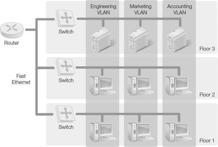
FIGURE 3-16 VLANs are logical partitions on a network that define groupings of hosts based on logical associations rather than physical connections to a switch.
The process of logically segmenting a network into smaller groups to manage access and resources is also called subnetting. Subnetting is the process where a collection of IP addresses is broken into smaller subsets to better identify systems on the network and to distribute resources. Segregating collections of computers and devices into departments or areas is a common use of subnetting. That way, all IP addresses in a particular range are assigned to a group with common objectives, location, or needs.
With IPv4, subnetting is necessary in very large networks because there are not enough available IPv4 addresses to assign one to each device. By subnetting, the pool of available addresses is expanded to allow more devices to have concurrent access to the network. This works by applying a subnet mask, which applies to a specific class of addressing. The address class differentiates how the address can be used. Use includes public, private, experimental, and multicast, which is when a single host sends messages to multiple network devices. Globally, IP addresses are managed by the Internet Assigned Numbers Authority (IANA).
IPv6 does not require the use of subnetting to expand the available pool of IP addresses for use in an organization, as there are many more addresses available under that scheme. Although not imposed by the need to make additional addresses available, logical network segregation is still important to allow for restriction of access, minimization of malware access, legal compliance, and other business reasons. IPv4 and IPv6 are covered in detail next.