
Chapter 6. Cisco Cyber Threat Defense and NetFlow
This chapter covers the following topics:
![]() Overview of the Cisco Cyber Threat Defense Solution
Overview of the Cisco Cyber Threat Defense Solution
![]() Deploying the Lancope StealthWatch System
Deploying the Lancope StealthWatch System
![]() Deploying NetFlow Secure Event Logging in the Cisco ASA
Deploying NetFlow Secure Event Logging in the Cisco ASA
![]() Configuring NetFlow in the Cisco Nexus 1V
Configuring NetFlow in the Cisco Nexus 1V
![]() Configuring NetFlow in the Cisco Nexus 7 Series
Configuring NetFlow in the Cisco Nexus 7 Series
![]() Configuring the Cisco NetFlow Generation Appliance
Configuring the Cisco NetFlow Generation Appliance
![]() Additional Cisco CTD Solution Components
Additional Cisco CTD Solution Components
Overview of the Cisco Cyber Threat Defense Solution
In Chapter 1, “Introduction to NetFlow and IPFIX,” you learned the benefits of NetFlow and a high-level overview of Cisco’s Cyber Threat Defense (CTD) Solution. Cisco has partnered with Lancope to deliver a solution that provides visibility into security threats by identifying suspicious traffic patterns in the corporate network. These suspicious patterns are then augmented with circumstantial information necessary to determine the level of threat associated with a particular incident. This solution allows a network administrator or security professional to analyze this information in a timely, efficient, and cost-effective manner for advanced cyber threats. This chapter provides a detailed coverage of Cisco CTD Solution. Before delving deeper into the details of the Cisco CTD Solution, let’s go over the current threat landscape and the attack continuum.
The Attack Continuum
Defending against cyber security attacks is becoming more challenging every day, and it is not going to get any easier. The threat landscape is evolving to a faster, more effective, and more efficient criminal economy profiting from attacks against users, enterprises, services providers, and governments. The organized cyber crime and exchange of exploits is booming and fueling a very lucrative economy. Bad actors nowadays have a clear understanding of the underlying security technologies and their vulnerabilities. Hacker groups now follow software development lifecycles, just like enterprises have their own. These bad actors perform quality-assurance testing against security products before releasing them into the underground economy. They continue to find ways to evade common security defenses. Attackers follow new techniques such as the following:
![]() Port and protocol hopping
Port and protocol hopping
![]() Encryption
Encryption
![]() Droppers
Droppers
![]() Social engineering
Social engineering
![]() Zero-day attacks
Zero-day attacks
Next-generation security defenses must be
![]() Visibility driven: Maintaining complete visibility gathering data from all potential attack vectors across the network fabric, endpoints (including mobile devices), email and web gateways, virtual machines in the data center, and the cloud.
Visibility driven: Maintaining complete visibility gathering data from all potential attack vectors across the network fabric, endpoints (including mobile devices), email and web gateways, virtual machines in the data center, and the cloud.
![]() Threat focused: Correlating all collected information with indicators of compromise (IOC) and other contextual information for network security administrators makes better decisions and take action. Keeping up with a constantly evolving threat landscape is almost impossible. Access controls reduce the attack surface, but attackers still get through. Security technologies and solutions must focus on understanding, detecting, and blocking attacks. These solutions require continuous analysis and security intelligence delivered from the cloud and shared across all products for better effectiveness.
Threat focused: Correlating all collected information with indicators of compromise (IOC) and other contextual information for network security administrators makes better decisions and take action. Keeping up with a constantly evolving threat landscape is almost impossible. Access controls reduce the attack surface, but attackers still get through. Security technologies and solutions must focus on understanding, detecting, and blocking attacks. These solutions require continuous analysis and security intelligence delivered from the cloud and shared across all products for better effectiveness.
![]() Platform based: Security now requires an integrated system of agile and open platforms that cover the network, endpoints, users, and the cloud. These platforms must be scalable and centrally managed for device configuration consistency.
Platform based: Security now requires an integrated system of agile and open platforms that cover the network, endpoints, users, and the cloud. These platforms must be scalable and centrally managed for device configuration consistency.
Security technologies and processes should not focus on detection, but also should provide the capability to mitigate the impact after a successful attack. Figure 6-1 illustrates the attack continuum.
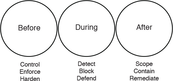
Security professionals must maintain visibility and control across the extended network during the full attack continuum:
![]() Before the attack takes place
Before the attack takes place
![]() During an active attack
During an active attack
![]() After an attacker starts to damage systems or steal information
After an attacker starts to damage systems or steal information
Cisco next-generation security products provide protection throughout the attack continuum. NetFlow is a vital component of the first version of the Cisco CTD Solution, and continues to play a vital role in its next generation. It provides visibility capabilities that are crucial for all three parts of the attack continuum. Devices such as the Cisco ASA with FirePOWER Services available on the Cisco ASA 5500-X series and ASA 5585-X Adaptive Security Appliances and Cisco’s Advanced Malware Protection (AMP) provide a security solution that help discover threats and enforce and harden policies before an attack takes place. In addition, you can detect, block, and defend against attacks that have already taken place with next-generation intrusion prevention systems (NGIPS), and email and web security appliances with AMP. These solutions provide the capabilities to contain and remediate an attack to minimize data loss and additional network degradation.
Cisco CTD Solution Components
In Chapter 1, you learned the different deployment scenarios for NetFlow. These deployment scenarios include the following:
![]() User access layer
User access layer
![]() Wireless LANs
Wireless LANs
![]() Internet edge
Internet edge
![]() Data center
Data center
![]() Firewalls
Firewalls
![]() NetFlow in site-to-site and remote access virtual private networks (VPNs)
NetFlow in site-to-site and remote access virtual private networks (VPNs)
These scenarios still apply for the Cisco CTD Solution.
The Cisco CTD Solution Version 2.0 uses the following next-generation security components:
![]() NetFlow and the Lancope StealthWatch System: For broad network visibility, user and flow context analysis, and incident response and network forensics
NetFlow and the Lancope StealthWatch System: For broad network visibility, user and flow context analysis, and incident response and network forensics
![]() Cisco FirePOWER and FireSIGHT: For real-time threat management and deep application inspection
Cisco FirePOWER and FireSIGHT: For real-time threat management and deep application inspection
![]() Advanced Malware Protection (AMP): Endpoint control with AMP for endpoints and network malware control with AMP for networks
Advanced Malware Protection (AMP): Endpoint control with AMP for endpoints and network malware control with AMP for networks
![]() Content Security Appliances and Services such as the Cisco Web Security Appliance (WSA) and Cloud Web Security (CWS): For dynamic threat control of web traffic, in addition to the Cisco Email Security Appliance (ESA) for dynamic threat control for email traffic
Content Security Appliances and Services such as the Cisco Web Security Appliance (WSA) and Cloud Web Security (CWS): For dynamic threat control of web traffic, in addition to the Cisco Email Security Appliance (ESA) for dynamic threat control for email traffic
![]() Cisco Identity Services Engine (ISE): For user and device identity integration with Lancope StealthWatch and remediation policy actions using pxGrid
Cisco Identity Services Engine (ISE): For user and device identity integration with Lancope StealthWatch and remediation policy actions using pxGrid
The Cisco CTD Solution supports Flexible NetFlow and NetFlow Version 9. Flexible NetFlow should be used in Cisco IOS Software for the latest technology and features for NetFlow, and should be considered for new deployments because its features allows-user configurable NetFlow record formats. In addition, Flexible NetFlow has several advantages, including tailoring a cache for specific applications not covered by NetFlow predecessor versions. Flexible NetFlow also provides better scalability, because flow record customization for particular application reduces number of flows to monitor.
Figure 6-2 shows a high-level topology of a few components of the Cisco CTD Solution.

NetFlow can be enabled at many different network infrastructure devices. In Figure 6-2, access switches, wireless access points managed by the Cisco Wireless LAN Controller (WLC), and Cisco ASA 5500-X Series Next-Generation Firewalls are configured for NetFlow. Lancope’s StealthWatch FlowCollector is collecting NetFlow from those devices. StealthWatch FlowCollector is a physical or virtual appliance that collects NetFlow data from infrastructure devices. The StealthWatch Management Console is deployed to provide centralized management for the StealthWatch FlowCollector appliance and provides real-time data correlation, visualization, and consolidated reporting of combined NetFlow and identity analysis.
Cisco FireSIGHT Management Center provides a centralized management and analysis platform for the Cisco NGIPS appliances and the Cisco ASA with FirePOWER Services. It provides support for role-based policy management, including a fully customizable dashboard with advanced reports and analytics.
Tip
The FireSIGHT Management Center and the Cisco ASA FirePOWER module require additional licenses. These licenses are installed in the FirePOWER module itself. No additional licenses are required in the Cisco ASA itself.
The Cisco CTD Solution provides identity awareness with a direct correlation between users and specific network events. The identity data can be obtained from the StealthWatch IDentity appliance or through integration with the Cisco Identity Services Engine (ISE). StealthWatch Management Console can also process user information (usernames) within NetFlow records from Cisco ASA appliances. The integration with Cisco ISE provides a rich capability to identify the who, what, where, when, and how of threats that could penetrate the network.
Note
The minimum requirement to perform identity capabilities is to deploy the Cisco ISE and one or more authenticating access devices in a valid Cisco TrustSec Monitoring Mode deployment.
NetFlow Platform Support
The following sections include information about the different platforms that support NetFlow.
Traditional NetFlow Support in Cisco IOS Software
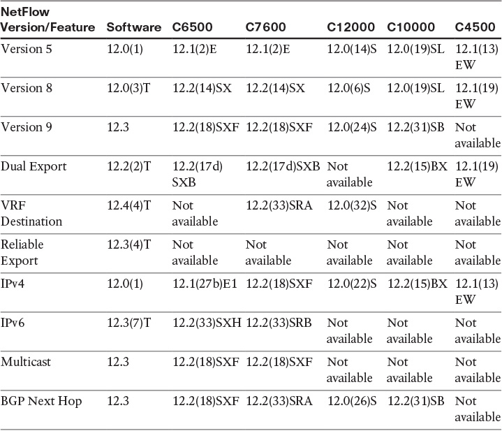
Table 6-1 lists the first Cisco IOS Software release in which traditional NetFlow support was introduced in the following platforms:
![]() Cisco Catalyst 6500 series switches
Cisco Catalyst 6500 series switches
![]() Cisco 7600 series routers
Cisco 7600 series routers
![]() Cisco 12000 series routers running Cisco IOS Software
Cisco 12000 series routers running Cisco IOS Software
![]() Cisco Catalyst 4500 series switches
Cisco Catalyst 4500 series switches

NetFlow Support in Cisco IOS-XR Software
Table 6-2 lists the first Cisco IOS-XR release in which traditional NetFlow support was introduced in the following platforms:
![]() Cisco Carrier Routing System (CRS-X)
Cisco Carrier Routing System (CRS-X)
![]() Cisco 12000 series routers running Cisco IOS Software
Cisco 12000 series routers running Cisco IOS Software
![]() Cisco ASR 9000 series Aggregation Services Routers
Cisco ASR 9000 series Aggregation Services Routers

Flexible NetFlow Support
Table 6-3 lists the first Cisco IOS Software or Cisco IOS-XE Software release in which Flexible NetFlow support was introduced, along with the respective feature, in the following platforms:
![]() Cisco Integrated Services Routers
Cisco Integrated Services Routers
![]() Cisco Integrated Services Routers Generation 2 (G2)
Cisco Integrated Services Routers Generation 2 (G2)
![]() Cisco 7200 series and Cisco 7300 series routers
Cisco 7200 series and Cisco 7300 series routers
![]() Cisco ASR 1000 series Aggregation Services Routers
Cisco ASR 1000 series Aggregation Services Routers


Table 6-3 Flexible NetFlow Support in ISR, ISR-G2, 7200 Series, 7300 Series, and Cisco ASR 1000 Series Aggregation Services Routers
Table 6-4 lists the first Cisco IOS-XE Software release in which Flexible NetFlow support was introduced, along with the respective feature, in the following platforms:
![]() Cisco Integrated Services Routers 4400 series
Cisco Integrated Services Routers 4400 series
![]() Cisco Cloud Services Router (CSR) 1000V series
Cisco Cloud Services Router (CSR) 1000V series


Table 6-5 lists the first Cisco NX-OS Software release in which Flexible NetFlow support was introduced, along with the respective feature, in the following platforms:
![]() Cisco Nexus 7000 series switches
Cisco Nexus 7000 series switches
![]() Cisco Nexus 1000V
Cisco Nexus 1000V
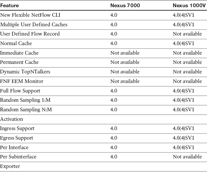
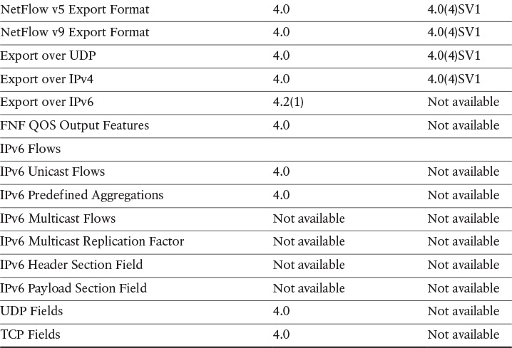
Table 6-5 Flexible NetFlow Support in the Cisco Nexus 7000 Series Switches and the Cisco Nexus 1000V
NetFlow Support in Cisco ASA
The Cisco ASA supports NetFlow Version 9 services with the NetFlow Secure Event Logging (NSEL) feature. NetFlow support was originally introduced in Cisco ASA Software Version 8.1(1). NetFlow filtering was introduced in 8.1(2) and the Cisco ASA NSEL feature was introduced in 8.2(1).
Deploying the Lancope StealthWatch System
Cisco has partnered with Lancope to deliver this solution. The Lancope StealthWatch System, available from Cisco, aggregates and normalizes considerable amounts of NetFlow data to apply security analytics to detect malicious and suspicious activity. The StealthWatch Management Console provides a rich graphical unit interface (GUI) with many visualizations and telemetry information.
Figure 6-3 shows an example of the many visualizations and reports that can be obtained in the StealthWatch Management Console.
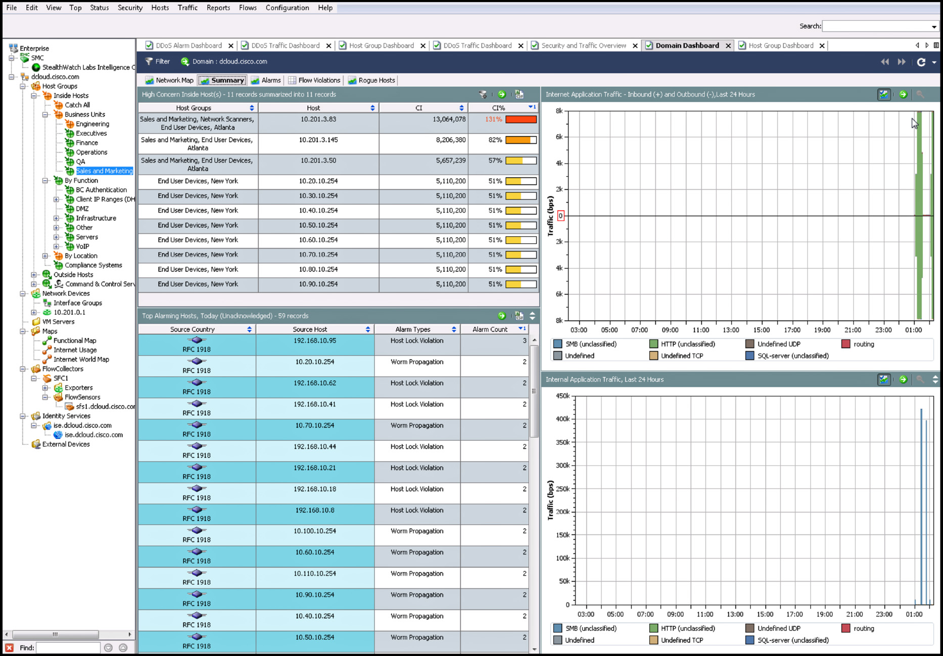
Figure 6-3 shows the Summary tab of the Domain Dashboard. A host (10.201.3.83) has been classified as a high concern host in the inside network. This host belongs to the Sales and Marketing host group in Atlanta. The Concern Index (CI) is a counter that accumulates as a host performs suspicious activity. The higher the number, the more suspicious activity the host has performed. The CI% is an indication of how far this host has deviated from baseline activity for its host group. In Figure 6-3, you can also see that several hosts in the 192.168.10.0 network have generated additional network alarms.
Figure 6-4 shows the StealthWatch Management Console DDoS Traffic Dashboard.

The Cisco ISE provides detailed user and device information to Lancope StealthWatch. Figure 6-5 shows the StealthWatch Management Console Identity and Device Table.

In Figure 6-5, you can see detailed information of active hosts in the inside network, along with the username of the actual user, MAC address identification, the router interface that observed such flow, and the start and end active time, in addition to other connection details.
The following are the primary components of the Lancope StealthWatch System:
![]() FlowCollector: A physical or virtual appliance that collects NetFlow data from infrastructure devices.
FlowCollector: A physical or virtual appliance that collects NetFlow data from infrastructure devices.
![]() StealthWatch Management Console: Used to manage the rest of the Lancope StealthWatch solution.
StealthWatch Management Console: Used to manage the rest of the Lancope StealthWatch solution.
![]() Flow licenses: Required to aggregate flows at the StealthWatch Management Console. Flow licenses define the volume of flows that may be collected.
Flow licenses: Required to aggregate flows at the StealthWatch Management Console. Flow licenses define the volume of flows that may be collected.
The following are optional components of the Lancope StealthWatch System:
![]() FlowSensor: A physical or virtual appliance that can generate NetFlow data when legacy Cisco network infrastructure components are not capable of producing line-rate, unsampled NetFlow data. Alternatively, the Cisco NGA can be used.
FlowSensor: A physical or virtual appliance that can generate NetFlow data when legacy Cisco network infrastructure components are not capable of producing line-rate, unsampled NetFlow data. Alternatively, the Cisco NGA can be used.
![]() FlowReplicator: A physical appliance used to forward NetFlow data as a single data stream to other devices.
FlowReplicator: A physical appliance used to forward NetFlow data as a single data stream to other devices.
Note
For the most up-to-date information about the support in each StealthWatch FlowCollector and FlowSensor appliance models and their specifications, go to Lancope’s website at http://lancope.com.
Like all NetFlow generators, the volume of NetFlow traffic generated by the StealthWatch FlowSensor varies based on the monitored traffic profile.
Deploying StealthWatch FlowCollectors
The StealthWatch FlowCollector can be deployed in the corporate network in several ways:
![]() A single StealthWatch FlowCollector collecting all NetFlow data in a centralized location
A single StealthWatch FlowCollector collecting all NetFlow data in a centralized location
![]() Multiple StealthWatch FlowCollector behind a load balancer in a centralized location
Multiple StealthWatch FlowCollector behind a load balancer in a centralized location
![]() Multiple StealthWatch FlowCollectors at multiple sites (usually placed close to the source producing the highest number of NetFlow records)
Multiple StealthWatch FlowCollectors at multiple sites (usually placed close to the source producing the highest number of NetFlow records)
NetFlow collection should be done as close to the NetFlow generator as possible to minimize network bandwidth and overhead impact. In an asymmetric routing situation, all devices in the asymmetric route should send NetFlow records to the same FlowCollector.
Figure 6-6 shows a topology example where a single StealthWatch FlowCollector is deployed collecting all NetFlow data from switches, a router, and a Cisco ASA in a centralized location.
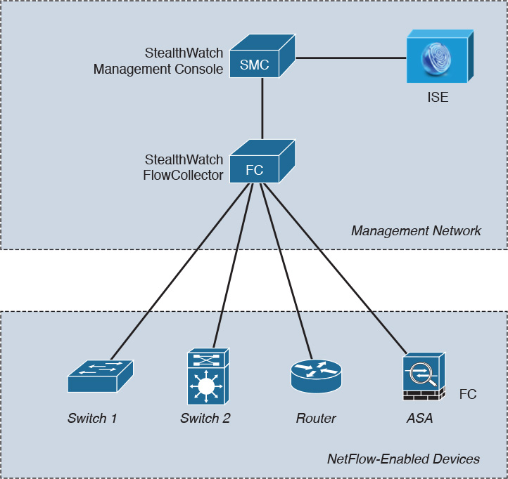
Figure 6-7 shows an example topology where three StealthWatch FlowCollectors are deployed behind a load balancer. For example, you can deploy the Citrix NetScaler 1000V on demand, anywhere in the data center, using the Cisco Nexus 1100 Series Cloud Services Platform (CSP) or running as a virtual appliance on VMWare ESXi or KVM. When running on KVM, you can integrate it with OpenStack using the Cisco Prime Network Services Controller. This load-balancing solution will help you scale your StealthWatch FlowCollectors (or any other collectors) more efficiently in your environment.
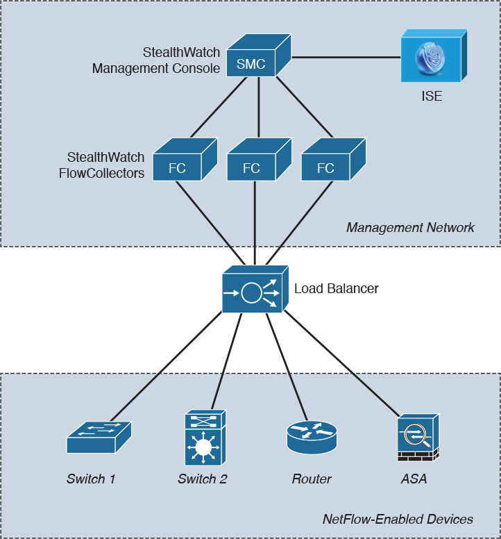
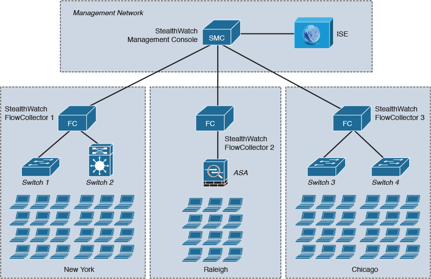
Figure 6-8 shows an example topology where three StealthWatch FlowCollectors are deployed in a distributed way, with one StealthWatch FlowCollector at each site (New York, Raleigh, and Chicago). This deployment has the advantage of limiting the overhead introduced by NetFlow.
If you have multiple geographically located sites, pay attention to bandwidth limitations between sites. As a best practice, a single FlowCollector should be used for as much related traffic as possible. However, the benefits of centralized collection diminish when the traffic is not similar.
Another best practice is that all NetFlow records belonging to a flow should be sent to the same StealthWatch FlowCollector. Duplicate NetFlow records can be a problem when trying to respond to an incident or analyze traffic patterns. StealthWatch FlowCollectors have a deduplication feature where it guarantees that the flow data is stored properly, while preserving the details about each flow exporter and eliminating the reporting of inflated traffic volumes.
When deploying StealthWatch FlowCollectors, you should consider several factors:
![]() The number of NetFlow generation devices (exporter count).
The number of NetFlow generation devices (exporter count).
![]() The rate of flows per second (fps) that is expected to be received.
The rate of flows per second (fps) that is expected to be received.
![]() The number of hosts (both inside and outside the network) for which the collector can maintain state. As a best practice, the number of inside hosts should not exceed 60 percent of the host count value.
The number of hosts (both inside and outside the network) for which the collector can maintain state. As a best practice, the number of inside hosts should not exceed 60 percent of the host count value.
![]() The amount of flow data to be stored.
The amount of flow data to be stored.
StealthWatch FlowCollectors come in two different form factors: appliances and virtual edition (VE). Table 6-6 lists the different StealthWatch FlowCollector appliances and high-level specifications.

Table 6-7 lists the StealthWatch FlowCollector VE high-level specifications depending on the amount of memory and the number of virtual CPUs.
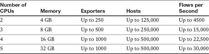
Note
As mentioned earlier in the chapter, for the most up-to-date information about the support in each StealthWatch FlowCollector appliance models and their specifications, go to Lancope’s website at http://lancope.com.
StealthWatch FlowReplicators
The StealthWatch FlowReplicator is an optional component of the Cisco CTD Solution. The StealthWatch FlowCollector exists as a physical or virtual appliance. The StealthWatch FlowReplicator supports Cisco NetFlow, IPFIX, and other vendors’ flow data. It combines multiple capabilities into a single device to streamline the collection and distribution of network and security data across the corporate network.
Figure 6-9 shows an example topology where the StealthWatch FlowReplicator (FR) is deployed collecting NetFlow, IPFIX, and syslog data from multiple devices in the network.

In Figure 6-9, the StealthWatch FR sends all NetFlow data to the StealthWatch FlowCollector 1 and all IPFIX data to the StealthWatch FlowCollector 2.
The StealthWatch FR can receive data from any connectionless UDP application and syslog messages and then replicate those to network analysis systems. In addition, StealthWatch FR can process Simple Network Management Protocol (SNMP) traps from network infrastructure devices and distribute them to several different SNMP management stations.
StealthWatch Management Console
The StealthWatch Management Console manages, coordinates, and configures all StealthWatch appliances, including the StealthWatch FlowCollector and the StealthWatch FlowReplicator. It is designed to correlate network intelligence across the corporate network primarily using NetFlow. The StealthWatch Management Console can also be configured with the Cisco ISE to receive authenticated session information to correlate flow and identity. The StealthWatch Management Console comes in two different form factors (just like the StealthWatch FlowCollectors): appliances and virtual edition (VE). Table 6-8 lists the different StealthWatch Management Console appliances and high-level specifications.
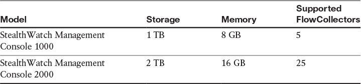
Table 6-9 lists the StealthWatch Management Console VE high-level specifications depending on the amount of memory and the number of virtual CPUs.

Deploying NetFlow Secure Event Logging in the Cisco ASA
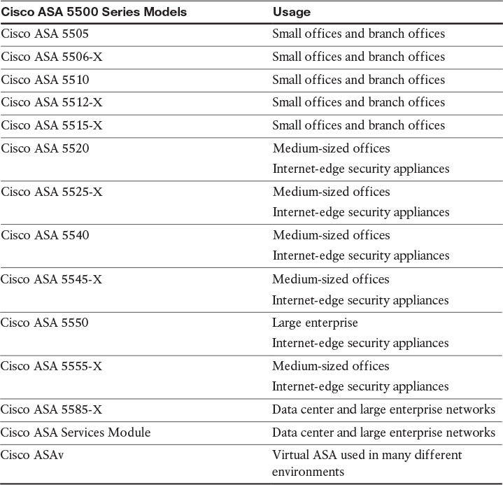
The Cisco ASA family comes in many shapes and sizes, but they all provide a similar set of features. Typically, the smaller the number of the model represents a smaller capacity for throughput. The main standalone appliance model number begins with a 55, but there are also devices in the Cisco ASA family that go into a switch, such as a 6500. Table 6-10 describes the various models of the ASA.
The Cisco ASA NetFlow implementation is also known as NetFlow Secure Event Logging (NSEL). The Cisco ASA supports NetFlow Version 9. NSEL provides a stateful IP flow tracking method that exports only those records that indicate significant events in a flow.
The following are the significant flow events that are tracked:
![]() Flow create
Flow create
![]() Flow teardown
Flow teardown
![]() Flow denied
Flow denied
![]() Flow update (provide periodic byte counters over the duration of the flow)
Flow update (provide periodic byte counters over the duration of the flow)
Note
The flow-denied events do not support flows that are denied by EtherType access control lists (ACLs). The flow-update events were introduced in Cisco ASA Software Versions 8.4(5) and 9.1(2).
The Cisco ASA NSEL events are typically time driven (similar to traditional NetFlow). However, these events may also be triggered by state changes in the flow.
All NSEL records generated by the Cisco ASA have an Event ID and an Extended Event ID field, which are used to describe the flow event.
Figure 6-10 lists the Cisco ASA NSEL major functions.

NSEL templates describe the format of the data records that are exported by the Cisco ASA. Each NSEL event can have several record formats or templates associated with it.
You can filter NSEL events using the Cisco ASA MPF; the traffic to be filtered or collected is matched based on the order in which classes are configured. It is important to remember that after a match is found, no other classes are checked.
NSEL records can be sent to different collectors, as illustrated in Figure 6-11.
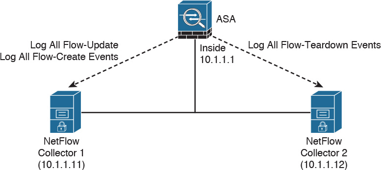
In Figure 6-11, a Cisco ASA is configured to send NSEL records to two different NetFlow collectors. In this configuration, the Cisco ASA sends all flow-create and flow-update events to Collector 1 and all flow-teardown events to Collector 2.
Deploying NSEL in Cisco ASA Configured for Clustering
You can configure multiple Cisco ASAs in a cluster. In each cluster, you can combine up to 16 Cisco ASAs into a single traffic processing system. Unlike in failover, each unit of a Cisco ASA cluster actively forwards transit traffic in both the single and multiple context modes; you do not need to artificially separate transit traffic as with active/active failover. Adjacent switches and routers load balance traffic between available cluster members via a cluster-spanned EtherChannel or IP routing.
Figure 6-12 illustrates a cluster with six Cisco ASAs.
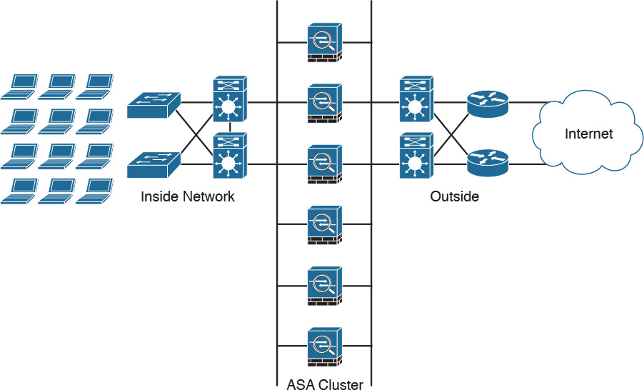
Any cluster member can fail at any given time without impacting transit traffic or disrupting other cluster units. Each unit always maintains a backup of each stateful connection entry on a different physical ASA. A cluster remains operational when two or more members fail at the same time, but some connections may have to reestablish. You configure and monitor the entire cluster from a single member (including NSEL). The configuration automatically replicates to all other units.
Unit Roles and Functions in Clustering
Unlike with failover, you do not have to make any special role designations when creating a cluster. All operational cluster members forward traffic at all times, but each of them plays one or more dynamic roles:
![]() Master and slave units: Cisco ASA cluster elects one member as the master; all other members become slaves. Similarly to failover, you typically configure clustering on one Cisco ASA and add other units later. That first unit becomes the master and remains in this role until it reloads or fails; you can also manually transition another unit into the master role with the cluster master unit command.
Master and slave units: Cisco ASA cluster elects one member as the master; all other members become slaves. Similarly to failover, you typically configure clustering on one Cisco ASA and add other units later. That first unit becomes the master and remains in this role until it reloads or fails; you can also manually transition another unit into the master role with the cluster master unit command.
![]() Flow owner: A single cluster member must process all packets that belong to a single connection. This ensures symmetry for proper state tracking. For each connection, one unit in the cluster becomes the flow owner. Each cluster member may own some flows. Typically, the unit that receives the first packet for a connection becomes its owner. If the original owner fails while a connection is still active, another unit assumes the ownership of that flow. Typically, any unit receiving a packet for an existing connection with no owner becomes its flow owner. A flow owner always maintains the full stateful connection entry.
Flow owner: A single cluster member must process all packets that belong to a single connection. This ensures symmetry for proper state tracking. For each connection, one unit in the cluster becomes the flow owner. Each cluster member may own some flows. Typically, the unit that receives the first packet for a connection becomes its owner. If the original owner fails while a connection is still active, another unit assumes the ownership of that flow. Typically, any unit receiving a packet for an existing connection with no owner becomes its flow owner. A flow owner always maintains the full stateful connection entry.
![]() Flow director: The concept of a flow director is central to the high-availability aspect of clustering. For each connection, the flow director always maintains the backup stateful information record. A flow owner periodically updates the flow director on the connection state. Other cluster members determine the identity of the flow owner by contacting the flow director. This mechanism of persistent backup flow ownership allows another unit to recover the connection state and assume its ownership if the original flow owner fails.
Flow director: The concept of a flow director is central to the high-availability aspect of clustering. For each connection, the flow director always maintains the backup stateful information record. A flow owner periodically updates the flow director on the connection state. Other cluster members determine the identity of the flow owner by contacting the flow director. This mechanism of persistent backup flow ownership allows another unit to recover the connection state and assume its ownership if the original flow owner fails.
Each cluster member knows which unit is the flow director for every possible transit connection.
The flow director maintains a stub connection entry with a limited set of stateful information. This approach enables a cluster to scale much higher in terms of the maximum connection count. If the flow owner happens to be the flow director for the same connection, another unit creates a backup stub connection entry to maintain high availability.
![]() Flow forwarder: Because a cluster relies on external stateless load balancing, it is possible for different directions of the same connection to land on different units. And because the flow owner must process all packets that belong to a single connection, other units must forward such asymmetrically received packets to the correct owner. A cluster member who receives a non-TCP-SYN packet for an unknown connection queries the respective flow director to determine whether the owner exists.
Flow forwarder: Because a cluster relies on external stateless load balancing, it is possible for different directions of the same connection to land on different units. And because the flow owner must process all packets that belong to a single connection, other units must forward such asymmetrically received packets to the correct owner. A cluster member who receives a non-TCP-SYN packet for an unknown connection queries the respective flow director to determine whether the owner exists.
Clustering NSEL Operations
In a cluster, each Cisco ASA establishes its own connection to the collectors and also manages and advertises its template independently. The fields in the header of the export packet include the following:
![]() System uptime
System uptime
![]() UNIX time that is synchronized across the cluster
UNIX time that is synchronized across the cluster
These fields are all local to an individual ASA. NetFlow collectors use the combination of the source IP address and source port of the packet to separate different exporters.
Note
The Cisco ASA supports in-cluster upgrades. Cisco ASAs that are participants in a cluster may run different software versions at a certain point in time. Subsequently, the template that each Cisco ASA supports may be different.
Configuring NSEL in the Cisco ASA
The following section includes step-by-step guidance on how to configure NSEL in the Cisco ASA using the Adaptive Security Device Manager (ASDM) and the command-line interface (CLI). The topology in Figure 6-13 is used in the following examples.
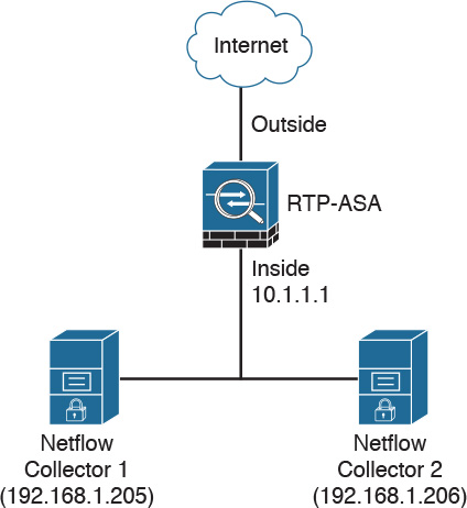
Figure 6-13 shows the topology of an office in the Research Triangle Park (RTP) in North Carolina. A Cisco ASA is configured with two NetFlow collectors.
Configuring NSEL in the Cisco ASA Using ASDM
In this section, you learn how to configure NSEL in the Cisco ASA. Complete the following steps to configure NSEL in the Cisco ASA using ASDM:
Step 1. Log in to ASDM and navigate to Configuration > Device Management > Logging > NetFlow, as illustrated in Figure 6-14.
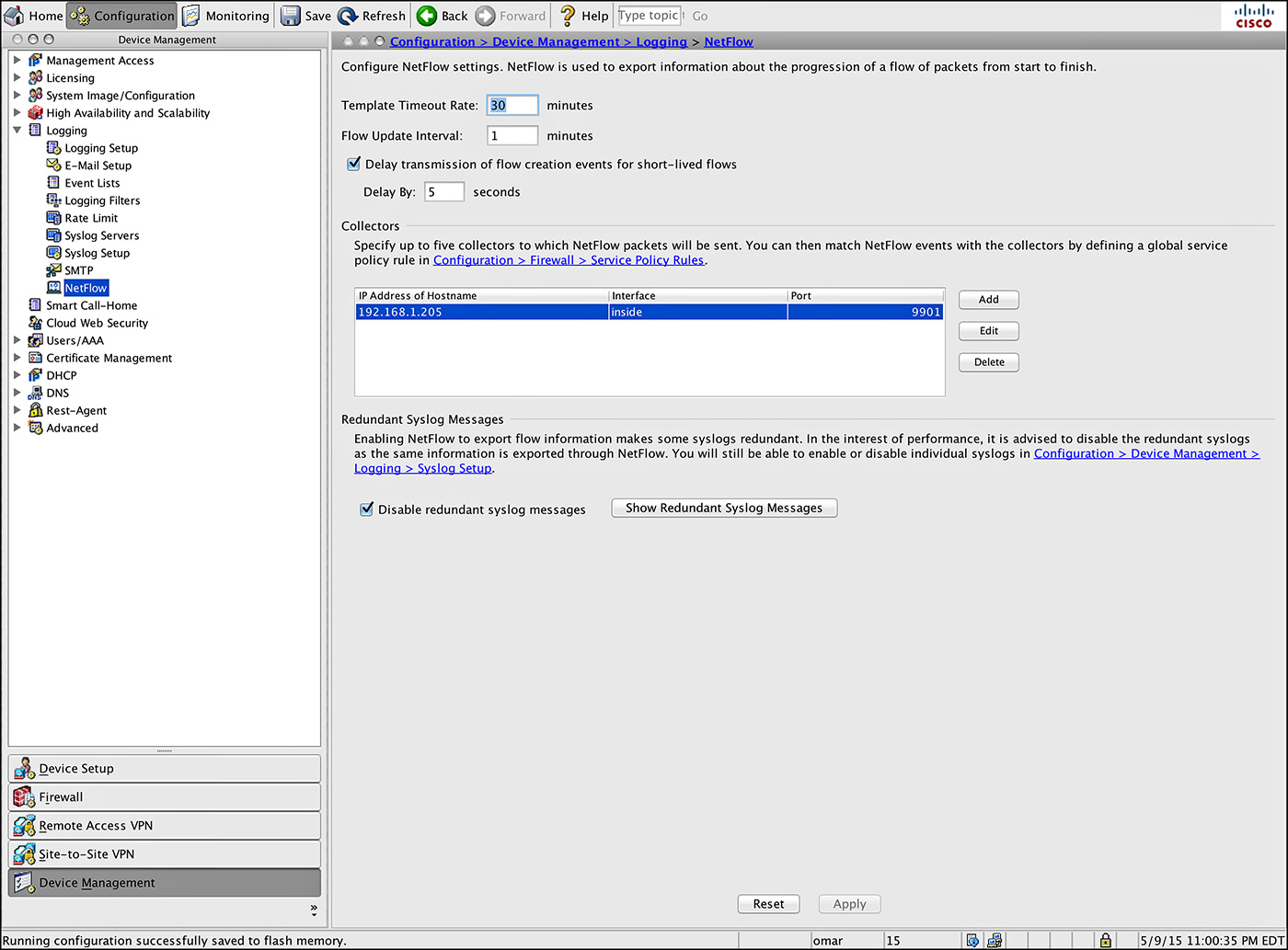
Step 2. Enter the template timeout rate (in minutes). This is the time at which template records are sent to all configured collectors. In this example, the default value is configured (30 minutes).
Step 3. Enter the flow update interval, which is the time interval between flow-update events. You can configure the flow update interval from 1 to 60 minutes. In this example, the default value is configured (1 minute).
Step 4. You can configure the Cisco ASA to delay the export of flow-creation events and process a single flow-teardown event instead of a flow-creation event and a flow-teardown event. To do so, check the Delay Export of Flow Creation Events for Short-Lived Flows checkbox. In this example, the number of seconds for the delay in the Delay By field is configured to 5 seconds.
Step 5. You can configure a maximum of five NetFlow collectors. In this example, a NetFlow collector with the IP address 192.168.1.205 is already configured in the inside interface and using UDP port 9901. Let’s add a second collector. To configure a collector, click Add. The Add NetFlow Collector dialog box will open, as shown in Figure 6-15.

Step 6. From the drop-down menu, choose the interface to which NetFlow packets will be sent. The inside interface is selected in this example.
Step 7. Enter the IP address or hostname and the UDP port number in the respective fields. The IP address of the new collector is 192.168.1.206 and the UDP port is 9901.
Step 9. Click Apply to apply the changes to the Cisco ASA configuration.
Step 10. Click Save to save the configuration.
Configuring NSEL in the Cisco ASA Using the CLI
Example 6-1 demonstrates how to configure NSEL using the CLI.
Example 6-1 Configuring NSEL Using the CLI
! Log in to the ASA and use the enable command to enter in privilege mode
rtp-asa> enable
Password: ****************
!
! Use the configure terminal command to enter in configuration mode
rtp-asa# configure terminal
!
! Adding a collector (192.168.1.205) and specifying UDP port 9901 for NSEL communi-
cation.
rtp-asa(config)# flow-export destination inside 192.168.1.205 9901
!
! Configuring the flow-export delay to 5 seconds.
rtp-asa(config)# flow-export delay flow-create 5
!
! Finishing the configuration and using the write memory command to save the
! configuration in the Cisco ASA.
rtp-asa(config)# end
rtp-asa# write memory
NSEL and Syslog
When you configure NSEL in the Cisco ASA, several syslog messages become redundant. It is recommended that you disable all redundant syslog messages. To disable all redundant syslog messages, navigate to Configuration > Device Management > Logging > NetFlow and check the Disable Redundant Syslog Messages check box. To display the redundant syslog messages and their status, click Show Redundant Syslog Messages and the Redundant Syslog Messages dialog box will appear, as shown in Figure 6-16.

Click OK to close this dialog box and Apply to apply the changes to the Cisco ASA configuration.
Example 6-2 demonstrates how to disable the redundant syslog messages using the CLI.
Example 6-2 Disabling Redundant Syslog Messages Using the CLI
rtp-asa(config)# no logging message 106015
rtp-asa(config)# no logging message 313001
rtp-asa(config)# no logging message 313008
rtp-asa(config)# no logging message 106023
rtp-asa(config)# no logging message 710003
rtp-asa(config)# no logging message 106100
rtp-asa(config)# no logging message 302015
rtp-asa(config)# no logging message 302014
rtp-asa(config)# no logging message 302013
rtp-asa(config)# no logging message 302018
rtp-asa(config)# no logging message 302017
rtp-asa(config)# no logging message 302016
rtp-asa(config)# no logging message 302021
rtp-asa(config)# no logging message 302020
Defining the NSEL Export Policy
The Cisco ASA does not send NetFlow (NSEL) packets to any configured collectors until you classify the traffic type it should be monitoring to generate the NetFlow events. For example, if you want it to monitor all traffic for NetFlow exports, specify a global policy that analyzes all traffic. NetFlow export policy is constructed via the MPF, as previously mentioned in this chapter. Follow these steps to successfully configure an export policy in ASDM:
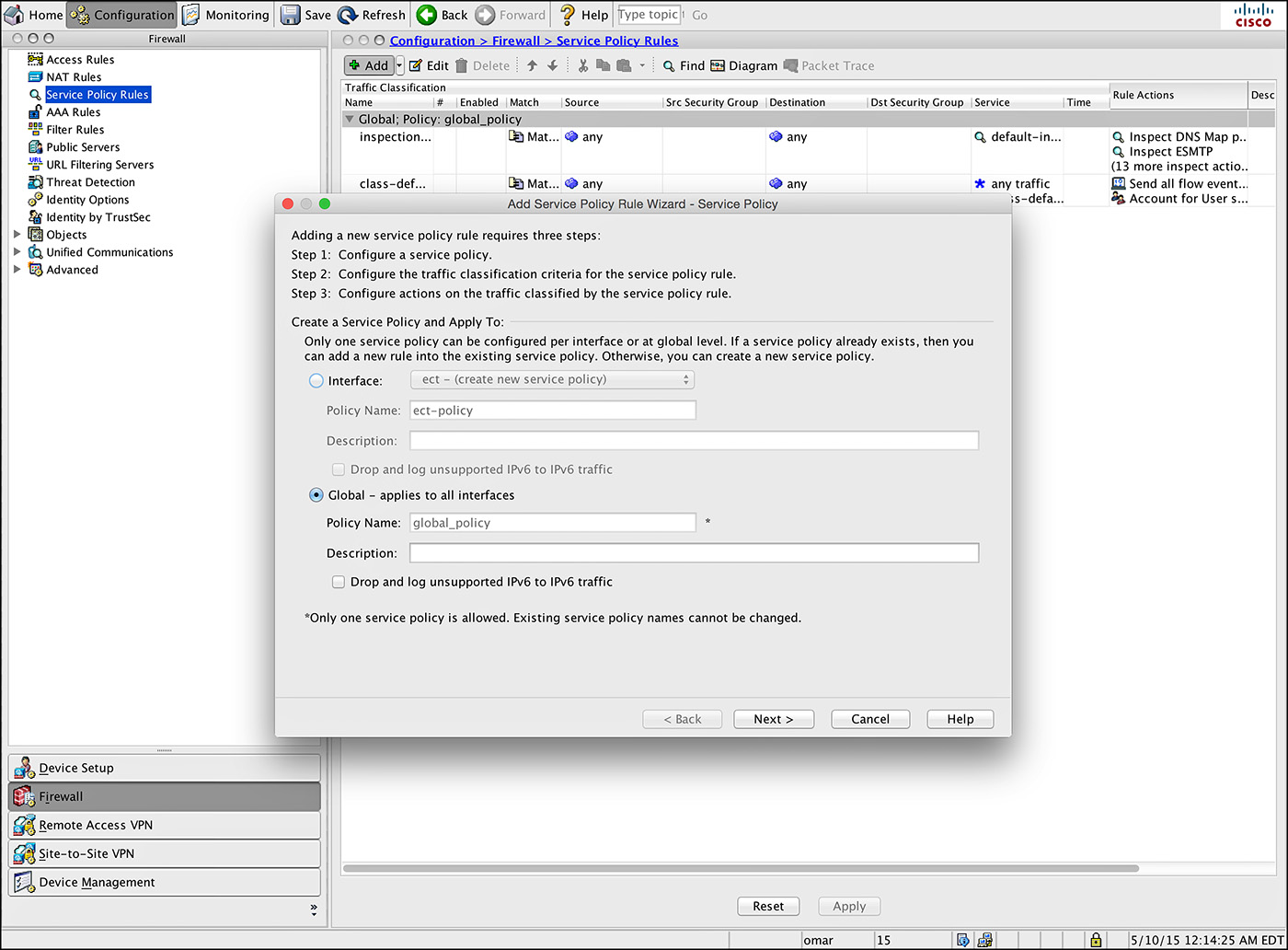
Step 1. Navigate to Configuration > Firewall > Service Policy Rules, select the inspection_default policy, and then choose Add > Insert After. ASDM launches an Add Service Policy Rule Wizard.
Step 2. Click the Global – Applies to All Interfaces radio button, as shown in Figure 6-17.
Step 3. Click Next.
Step 4. Under Create a New Traffic Class, specify a traffic class name of NetFlow. Check the Any Traffic check box as the traffic match criteria, as shown in Figure 6-18.

Step 5. Click Next.
Step 6. Under Rule Actions, navigate to the NetFlow tab and click Add. A new window opens where you can specify the flow event type, as shown in Figure 6-19.
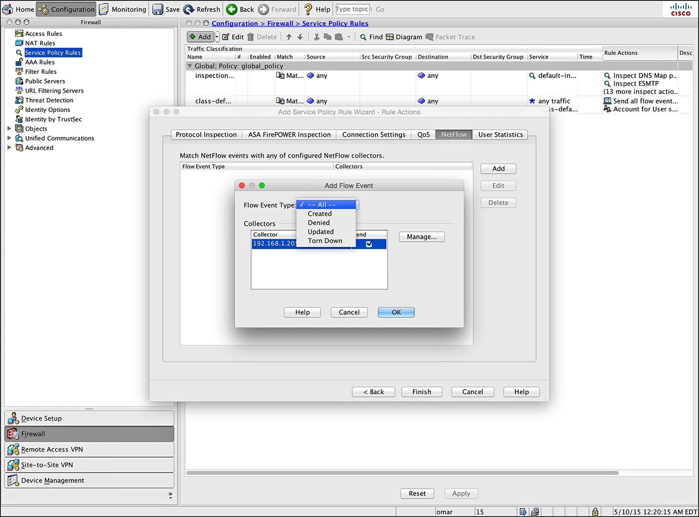
Step 7. Select All and check the Send check box next to the collector’s IP address. The collector that was previously configured is displayed.
Step 8. Click OK and then click Finish to complete defining a NetFlow export policy.
Example 6-3 demonstrates how to define the NSEL export policy using the CLI.
Example 6-3 Defining an NSEL Export Policy
rtp-asa(config)# class-map NetFlow
rtp-asa(config-cmap)# match any
rtp-asa(config-cmap)# policy-map global_policy
rtp-asa(config-pmap)# class NetFlow
rtp-asa(config-pmap-c)# flow-export event-type all destination 192.168.1.205
Monitoring NSEL
You can use syslog messages to troubleshoot errors or monitor system usage and performance. You can use the show flow-export counters command to display flow export counters, including statistical data and error data, as demonstrated in Example 6-4.
Example 6-4 show flow-export counters Command Output
rtp-asa# show flow-export counters
destination: inside 192.168.1.205 9901
Statistics:
packets sent 348392
Errors:
block allocation failure 0
invalid interface 0
template send failure 0
no route to collector 0
failed to get lock on block 0
source port allocation failure 0
You can list all syslog messages that are captured by NSEL events with the show logging flow-export-syslogs command. You can use the show running-config logging command to display disabled syslog messages.
Configuring NetFlow in the Cisco Nexus 1000V
This section describes how to configure NetFlow in the Cisco Nexus 1000V virtual switch. The topology illustrated in Figure 6-20 is used in the following examples.

You can define new flow records or use the pre-defined Cisco Nexus 1000V flow record. You can use the show flow record netflow-original command to display the predefined flow records, as shown in Example 6-5.
Example 6-5 Displaying Predefined Flow Records
nexus1000v# show flow record netflow-original
Flow record netflow-original:
Description: Traditional IPv4 input NetFlow with origin ASs
No. of users: 0
Template ID: 0
Fields:
match ipv4 source address
match ipv4 destination address
match ip protocol
match ip tos
match transport source-port
match transport destination-port
match interface input
match interface output
match flow direction
collect routing source as
collect routing destination as
collect routing next-hop address ipv4
collect transport tcp flags
collect counter bytes
collect counter packets
collect timestamp sys-uptime first
collect timestamp sys-uptime last
nexus1000v#
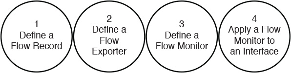
Figure 6-21 lists the high-level steps to configure NetFlow in the Cisco Nexus 1000V.
Defining a Flow Record
Example 6-6 demonstrates how to define a flow record in the Cisco Nexus 1000V.
Example 6-6 Defining a Flow Record in the Cisco Nexus 1000V
nexus1000v# config terminal
nexus1000v(config)# flow record MyRecord
nexus1000v(config-flow-record)# match ipv4 destination address
nexus1000v(config-flow-record)# collect counter packets
In Example 6-6, a flow record called MyRecord is defined. It is configured to match packets based on IPv4 destination addresses. The collect subcommand is used to define the information to collect in the flow record. The counter keyword can be used collect flow record information in one of the following formats:
![]() Bytes
Bytes
![]() Packets
Packets
Bytes and packets are collected in 32-bit counters unless the long 64-bit counter is specified. You can also use the collect timestamp sys-uptime subcommand to collect the system up time for the first or last packet in the flow. In addition, you can use the collect transport tcp flags subcommand to collect the TCP transport layer flags for the packets in the flow.
To show the flow record, you can use the show flow record name command, as demonstrated in Example 6-7.
Example 6-7 show flow record Command Output
nexus1000v# show flow record MyRecord
Flow record MyRecord:
No. of users: 0
Template ID: 0
Fields:
match ipv4 destination address
collect counter packets
Defining the Flow Exporter
Example 6-8 demonstrates how to define a flow exporter in the Cisco Nexus 1000V.
Example 6-8 Defining a Flow Exporter in the Cisco Nexus 1000V
nexus1000v(config)# flow exporter Exporter1
nexus1000v(config-flow-exporter)# destination 192.168.1.205
nexus1000v(config-flow-exporter)# source mgmt 0
nexus1000v(config-flow-exporter)# transport udp 9901
nexus1000v(config-flow-exporter)# version 9
nexus1000v(config-flow-exporter-version-9)# option exporter-stats timeout 1200
nexus1000v(config-flow-exporter-version-9)# template data timeout 1200
In Example 6-8, the flow exporter Exporter1 command defines the flow exporter. The name of the flow exporter is Exporter1 in this example. The destination subcommand specifies the IP address of the destination interface for the flow exporter. The destination in the example is 192.168.1.10.
In Example 6-8, the source interface from which the flow records are sent to the NetFlow collector is management 0 (mgmt 0). The destination UDP port is set to 9901. The NetFlow version is set to Version 9. The option exporter-stats timeout 1100 subcommand specifies the exporter statistics to 1100 seconds. The template data timeout 1100 subcommand is entered to set the template data resend timer to 1100 seconds.
You can use the show flow exporter name command to display the flow exporter statistics, as demonstrated in Example 6-9.
Example 6-9 show flow exporter Command Output
nexus1000v# show flow exporter Exporter1
Flow exporter Exporter1:
Destination: 192.168.1.205
VRF: default (1)
Destination UDP Port 9901
Source Interface Mgmt0
DSCP 2
Export Version 9
Exporter-stats timeout 1200 seconds
Data template timeout 1200 seconds
Exporter Statistics
Number of Flow Records Exported 55
Number of Templates Exported 0
Number of Export Packets Sent 0
Number of Export Bytes Sent 0
Number of Destination Unreachable Events 0
Number of No Buffer Events 0
Number of Packets Dropped (No Route to Host) 0
Number of Packets Dropped (other) 0
Number of Packets Dropped (LC to RP Error) 0
Number of Packets Dropped (Output Drops) 1
Time statistics were last cleared: Never
Defining a Flow Monitor
Example 6-10 demonstrates how to define a flow monitor in the Cisco Nexus 1000V.
Example 6-10 Defining a Flow Monitor in the Cisco Nexus 1000V
nexus1000v(config)# flow monitor MyMonitor
nexus1000v(config-flow-monitor)# exporter Exporter1
nexus1000v(config-flow-monitor)# record MyRecord
nexus1000v(config-flow-monitor)# cache size 10000
In Example 6-10, a flow monitor called MyMonitor is configured. The previously configured flow exporter and flow record are applied to the flow monitor. The cache size is configured to 10,000 entries. The cache is an optional command, but it is useful to limit the impact of the monitor cache on memory and performance.
You can use the show flow monitor name command to display the flow monitor statistics, as shown in Example 6-11.
Example 6-11 show flow monitor Command Output
nexus1000v# show flow monitor MyMonitor
Flow Monitor MyMonitor:
Use count: 0
Inactive timeout: 15
Active timeout: 1800
Cache Size: 10000
Applying the Flow Monitor to an Interface
The final step is to apply the flow monitor to an interface in the Cisco Nexus 1000V. Example 6-12 demonstrates how to assign the previously configured flow monitor to interface veth2.
Example 6-12 Applying the Flow Monitor to an Interface
nexus1000v(config)# interface veth 2
nexus1000v(config-if)# ip flow monitor MyMonitor output
The output keyword specifies that the flow monitor will be applied outbound (for output packets).
You can use the show flow interface command to display the flow monitor configuration under a given interface, as demonstrated in Example 6-13.
Example 6-13 show flow interface Command Output
nexus1000v(config-if)# show flow interface veth 2
Interface veth 2:
Monitor: MyMonitor
Direction: Output
You can use the show flow monitor MyMonitor cache command to display the flow monitor NetFlow cache.
Configuring NetFlow in the Cisco Nexus 7000 Series
The NetFlow configuration in the Cisco Nexus 7000 is practically the same as in the rest of the Nexus switches (including the Cisco Nexus 1000V, which was just covered). The steps are the same:
Step 1. Define a flow record.
Step 2. Define a flow exporter.
Step 3. Define a flow monitor.
Step 4. Apply the flow monitor to an interface.
NetFlow CLI commands are not available until you enable the NetFlow feature with the feature netflow command.
Example 6-14 demonstrates how to define a flow record in the Cisco Nexus 7000.
Example 6-14 Defining a Flow Record in the Cisco Nexus 7000
n7k(config)# feature netflow
n7k(config)# flow record myRecord
n7k(config-flow-record)# description Custom-Flow-Record
n7k(config-flow-record)# match ipv4 source address
n7k(config-flow-record)# match ipv4 destination address
n7k(config-flow-record)# match transport destination-port
n7k(config-flow-record)# collect counter bytes
n7k(config-flow-record)# collect counter packets
Example 6-15 demonstrates how to define a flow exporter in the Cisco Nexus 7000.
Example 6-15 Defining a Flow Exporter in the Cisco Nexus 7000
n7k(Config)# flow exporter myExporter
n7k(Config-flow-exporter)# destination 192.168.11.2
n7k(Config-flow-exporter)# source Ethernet2/2
n7k(Config-flow-exporter)# version 9
Example 6-16 demonstrates how to define a flow monitor with a custom record in the Cisco Nexus 7000.
Example 6-16 Defining a Flow Monitor with a Custom Record in the Cisco Nexus 7000
n7k(config)# flow monitor myMonitor
n7k(config-flow-monitor)# description Applied Inbound on Ethernet 2/1
n7k(config-flow-monitor)# record myRecord
n7k(config-flow-monitor)# exporter myExporter
Example 6-17 demonstrates how to define a flow monitor with an original record in the Cisco Nexus 7000.
Example 6-17 Defining a Flow Monitor with an Original Record in the Cisco Nexus 7000
n7k(config)# flow monitor myMonitor2
n7k(config-Netflow-Monitor)# description monitor using predefined record
n7k(config-Netflow-Monitor)# record netflow-original
n7k(config-Netflow-Monitor)# exporter myExporter
Example 6-18 demonstrates how to adjust the NetFlow timers in the Cisco Nexus 7000.
Example 6-18 Adjusting the NetFlow Timers in the Cisco Nexus 7000
n7k(config)# flow timeout active 120
n7k(config)# flow timeout inactive 32
n7k(config)# flow timeout fast 32 threshold 100
n7k(config)# flow timeout session
n7k(config)# flow timeout aggressive threshold 75
Example 6-19 demonstrates configure sampled NetFlow in the Cisco Nexus 7000.
Example 6-19 Configuring Sampled NetFlow in the Cisco Nexus 7000
n7k(config)# sampler mySampler
n7k(config-flow-sampler)# mode 1 out-of 1000
Example 6-20 demonstrates how to apply a NetFlow monitor and sampler to an interface in the Cisco Nexus 7000.
Example 6-20 Applying a NetFlow Monitor and Sampler
n7k(config)# interface Ethernet2/1
n7k(config-if)# ip flow monitor myMonitor input sampler mySampler
Configuring the Cisco NetFlow Generation Appliance
The Cisco NetFlow Generation Appliance (NGA) can be deployed at strategic sections of a data center or any other places in the corporate network to collect network traffic using Switch Port Analyzer (SPAN) and network taps. Figure 6-22 shows two Cisco NGAs configured to generate NetFlow records for in the data center.
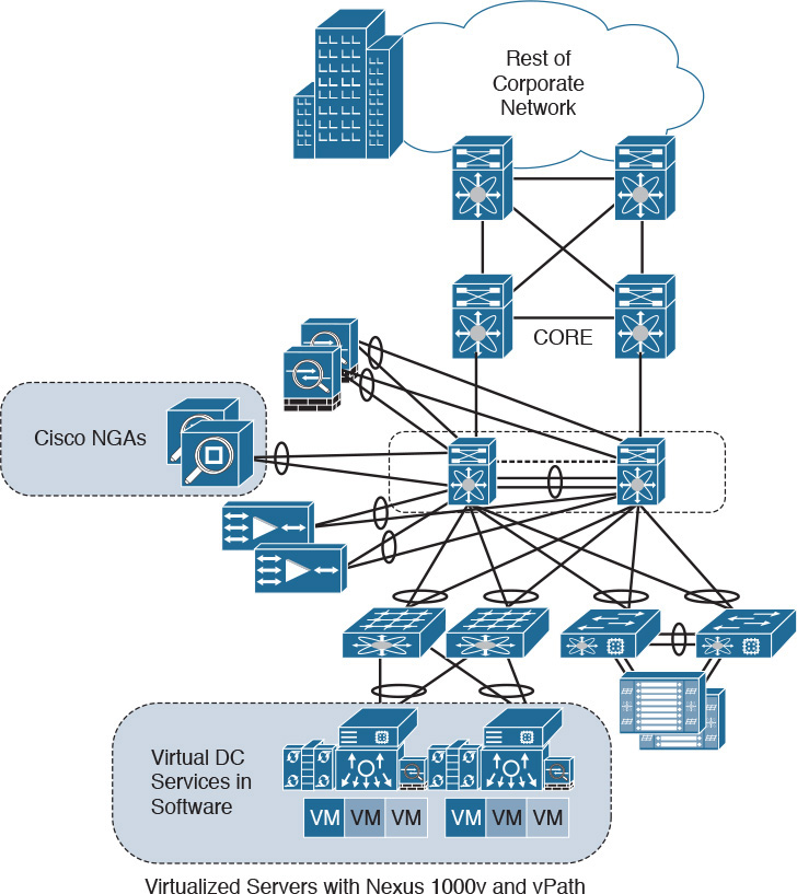
The Cisco NGA supports NetFlow Versions 5 and 9. It also supports IPFIX. The Cisco NGA has four 10G monitoring interfaces and up to four independent flow caches and flow monitors. Subsequently, the Cisco NGA can receive up to 40 gigabits of data and support various combinations of data ports, record templates, and export parameters. This is important to consider when deploying the Cisco NGA in the data center. As a best practice, the Cisco NGA monitoring interfaces should be sourced from network chokepoints to guarantee complete network traffic visibility in the data center.
Initializing the Cisco NGA
To perform the initial system configuration on the Cisco NGA appliance, follow these steps:
Step 1. Log in to the appliance through the console interface.
Step 2. The system prompts you to change the password. The default username is root, with a default password of root. It is highly recommended that you change the password to a complex password, using a password that contains at least eight characters and contains numbers, uppercase and lowercase letters, and symbols.
Step 3. Configure the management port IP address and subnet mask information using the following CLI command:
ip address 192.168.1.23 255.255.255.0
In this example, the Cisco NGA is configured with the IP address 192.168.1.23 and a 24-bit subnet mask (255.255.255.0).
Step 4. To configure the Cisco NGA’s default gateway address, use the ip gateway ip_address command, as demonstrated here, where the default gateway is 192.168.1.1:
ip gateway 192.168.1.1
Step 5. (Optional) Enter the following information for your DNS server IP address using the ip nameserver ip_address command.
Step 6. You can use the show ip command to verify the configuration.
Step 7. The next step is to enable the web interface. The Cisco NGA has the ability to autopopulate NetFlow components. Use the ip http server enable command to enable the web interface for standard web access or the ip http secure server enable for secure web access (recommended).
Step 8. Press Enter to use the default web administrator username (admin).
Step 9. Enter a password for the web administrator. The Cisco NGA supports only one web user account.
Step 10. You can direct packets to any of the four data ports on the NGA using either or both of the following methods:
![]() Enabling SPAN monitoring sessions (otherwise known as port mirroring) from the Cisco Nexus or Cisco Catalyst switches
Enabling SPAN monitoring sessions (otherwise known as port mirroring) from the Cisco Nexus or Cisco Catalyst switches
![]() Using network taps, which are hardware devices that provide a copy of the packet that flows across a network link
Using network taps, which are hardware devices that provide a copy of the packet that flows across a network link
Step 11. The Cisco NGA can export flow records containing the input and output interface of the device (switch) rather than NGA data port interface index if your traffic source is a Cisco Nexus 5000 or Cisco Nexus 7000 series switch. You must configure the IP address and login credentials of your traffic source as a managed device. As a best practice, configure the IP address of your traffic source in the Cisco NGA as a managed device.
Configuring NetFlow in the Cisco NGA via the GUI
The Cisco NGA supports the following:
![]() Up to ten NetFlow filters to define which flows are to be sent to certain collectors. This allows you to use your collector’s analysis applications and load balance NetFlow data across collectors.
Up to ten NetFlow filters to define which flows are to be sent to certain collectors. This allows you to use your collector’s analysis applications and load balance NetFlow data across collectors.
![]() Up to four managed devices.
Up to four managed devices.
![]() Up to six collectors.
Up to six collectors.
![]() Up to four independent flow monitors (flow caches) may be active simultaneously. Each monitor supports up to three records (one IPv4 record, one IPv6 record, and one Layer 2 record type).
Up to four independent flow monitors (flow caches) may be active simultaneously. Each monitor supports up to three records (one IPv4 record, one IPv6 record, and one Layer 2 record type).
To configure NetFlow in the Cisco NGA through the web interface, follow these steps:
Step 1. You can perform the Quick Setup NetFlow configuration (which is the easiest configuration to export NetFlow Version 5 or 9 packets to a collector) by navigating to Setup > Quick Setup.
Step 2. Define a unique name to identify the NetFlow configuration.
Step 3. Define one or more data ports.
Step 4. Define the NetFlow collector IP address in the Collector Address (IPv4) field.
Step 5. Enter the UDP port for communication. The default port is 2055.
Step 6. Define the NetFlow version (5 or 9).
Step 7. Click Submit.
Step 8. Select Cyber_Example_monitor on the Monitor tab and click Activate/Inactivate. This will enable the newly created flow monitor to generate NetFlow information for the input traffic and send it to the NetFlow collector.
Configuring NetFlow in the Cisco NGA via the CLI
This section covers how to configure NetFlow in the Cisco NGA via its CLI. Example 6-21 demonstrates how to create an IPv4 flow record using the key and non-key fields.
Example 6-21 Creating an IPv4 Flow Record Using the Key and Non-Key Fields
[email protected]# flow record IPv4 myRecord
[email protected](sub-record)# match input-interface
[email protected](sub-record)# match ip protocol
[email protected](sub-record)# match destination
[email protected](sub-record)# match source
[email protected](sub-record)# match ip tos
[email protected](sub-record)# match transport destination-port
[email protected](sub-record)# match transport source-port
[email protected](sub-record)# match datalink mac-destination
[email protected](sub-record)# match datalink mac-source
[email protected](sub-record)# collect classification application-id
[email protected](sub-record)# collect counter bytes
[email protected](sub-record)# collect timestamp sys-uptime first
[email protected](sub-record)# collect icmp code
[email protected](sub-record)# collect icmp type
[email protected](sub-record)# collect timestamp sys-uptime last
[email protected](sub-record)# collect ip max-ttl
[email protected](sub-record)# collect ip min-ttl
[email protected](sub-record)# collect counter packets
[email protected](sub-record)# collect transport tcp flags
Example 6-22 demonstrates how to define the flow collector.
Example 6-22 Defining the Flow Collector
[email protected]# flow collector myCollector
[email protected](sub-collector)# address 192.168.1.205
[email protected](sub-collector)# transport udp destination-port 2055
Example 6-23 demonstrates how to define the flow exporter.
Example 6-23 Defining the Flow Exporter
[email protected]# flow exporter myExporter
[email protected](sub-exporter)# version v9
[email protected](sub-exporter)# template-period 1
[email protected](sub-exporter)# option-period 1
[email protected](sub-exporter)# policy multi-destination
[email protected](sub-exporter)# destination myCollector
The name of the flow exporter in Example 6-23 is myExporter. NetFlow Version 9 is used in this example. The Cisco NGA is configured to send NetFlow data templates, option templates, and option data collectors every minute (1). The exporting policy is set to multi-destination so that the exporter will send the same NetFlow packet to all collectors set in the exporter. You can also configure the exporting policy with the weighted-round-robin option. The previously defined collector (myCollector) is used in this exporter.
Example 6-24 demonstrates how to define the flow monitor. The flow monitor represents the device’s NetFlow database and links together the flow record and the flow exporter with any or all of the four data ports on the NGA.
Example 6-24 Defining the Flow Monitor
[email protected]# flow monitor myMonitor
[email protected](sub-monitor)# record myRecord
[email protected](sub-monitor)# exporter myExporter
[email protected](sub-monitor)# dataport 1
[email protected](sub-monitor)# tunnel inner
[email protected](sub-monitor)# cache size 100
[email protected](sub-monitor)# cache type standard
[email protected](sub-monitor)# cache timeout active 60
[email protected](sub-monitor)# cache timeout inactive 15
In Example 6-24, the Cisco NGA’s flow monitor is configured to track the innermost IP addresses, by using the tunnel inner command. The tunnel inner command is used to dictate how the flow monitor will handle network packets that are tunneled and have more than one set of IP addresses. You can also configure the Cisco NGA’s flow monitor to track the outermost IP addresses. The total cache memory space to allocate for this monitor instance is set to 100. The cache type is set to standard cache mode. This allows inactive flows to be removed from the cache and memory to be made available for a new flow to use. Alternatively, you can configure permanent cache mode, where flows are never deleted from the cache. The active timeout is set to 60 seconds (recommended) and the inactive timeout is set to 15 seconds.
Tip
You can use the show cache statistics rates monitor_name command to display the rate of raw traffic being processed and the number of flows being created and forwarded to the exporter engine. Also, you can use the show collector statistics collector_name command to display the information about NetFlow packets being sent to the collector.
Additional Cisco CTD Solution Components
The following sections describe the additional Cisco CTD Solution components.
Cisco ASA 5500-X Series Next-Generation Firewalls and the Cisco ASA with FirePOWER Services
The Cisco ASA family provides a very comprehensive set of features and next-generation security capabilities. For example, it provides capabilities such as simple packet filtering (normally configured with ACLs) and stateful inspection. The Cisco ASA also provides support for application inspection/awareness. It can listen in on conversations between devices on one side and devices on the other side of the firewall. The benefit of listening in is so that the firewall can pay attention to application layer information.
The Cisco ASA also supports Network Address Translation (NAT) and the ability to act as a Dynamic Host Configuration Protocol (DHCP) server, client, or both. The Cisco ASA supports most of the interior gateway routing protocols, including Routing Information Protocol (RIP), Enhanced Interior Gateway Routing Protocol (EIGRP), and Open Shortest Path First (OSPF). It also supports static routing. It also can be implemented as a traditional Layer 3 firewall, which has IP addresses assigned to each of its routable interfaces. The other option is to implement a firewall as a transparent (Layer 2) firewall, in which the actual physical interfaces receive individual IP addresses, but a pair of interfaces operates like a bridge. Traffic that is going across this two-port bridge is still subject to the rules and inspection that can be implemented by the ASA. In addition, the Cisco ASA is often used a headend or remote-end device for VPN tunnels for both remote-access VPN users and site-to-site VPN tunnels. It supports IPsec and Secure Sockets Layer (SSL)-based remote-access VPNs. The SSL VPN capabilities include support for clientless SSL VPN and the full AnyConnect SSL VPN tunnels.
The Cisco ASA also provides a basic botnet traffic filtering feature. A botnet is a collection of computers that have been compromised and are willing to follow the instructions of someone who is attempting to centrally control them (for example, 200,000 machines all willing [or so commanded] to send a flood of ping requests to the IP address dictated by the person controlling these devices). Often, users of these computers have no idea that their computers are participating in this coordinated attack. The ASA works with an external system at Cisco that provides information about the Botnet Traffic Filter Database and so can protect against this.
Cisco introduced the Cisco ASA FirePOWER module as part of the integration of the SourceFire technology.
Note
SourceFire was a company that Cisco acquired to expand its security portfolio. The Cisco ASA FirePOWER module provides NGIPS, application visibility and control (AVC), URL filtering, and AMP. This module runs as a separate application from the classic Cisco ASA software. The Cisco ASA FirePOWER module can be a hardware module on the ASA 5585-X only or a software module that runs in a solid-state drive (SSD) in all other models.
The Cisco ASA FirePOWER module can be managed by the FireSIGHT Management Center. The FireSIGHT Management Center and the Cisco ASA FirePOWER module require additional licenses. These licenses are installed in the FirePOWER module itself. No additional licenses are required in the Cisco ASA itself.
Note
The Cisco ASA 5500-X Series Next-Generation Firewalls LiveLessons (Workshop): Deploying and Troubleshooting Techniques (ISBN-13: 978-1-58720-570-5) covers step-by-step instructions on how to deploy, configure, and troubleshoot the firewall features of the Cisco ASA 5500-X Series Next-Generation Firewalls, including an introduction of Cisco ASA with FirePOWER Services.
Next-Generation Intrusion Prevention Systems
As a result of the SourceFire acquisition, Cisco expanded its NGIPS portfolio with the following products:
![]() Cisco FirePOWER 9300 series appliances: High-performance appliances designed for service providers and large enterprises. These are modular appliances that can also run Cisco ASA software, Cisco FirePOWER Next-Generation IPS Services, and even Radware’s denial of service (DoS) mitigation software.
Cisco FirePOWER 9300 series appliances: High-performance appliances designed for service providers and large enterprises. These are modular appliances that can also run Cisco ASA software, Cisco FirePOWER Next-Generation IPS Services, and even Radware’s denial of service (DoS) mitigation software.
![]() Cisco FirePOWER 8000 series appliances: High-performance appliances running Cisco FirePOWER Next-Generation IPS Services. These appliances support throughput speeds from 2 Gbps up through 60 Gbps.
Cisco FirePOWER 8000 series appliances: High-performance appliances running Cisco FirePOWER Next-Generation IPS Services. These appliances support throughput speeds from 2 Gbps up through 60 Gbps.
![]() Cisco FirePOWER 7000 Series Appliances: These are the base platform for the Cisco FirePOWER Next-Generation IPS software. They support throughput speeds from 50 Mbps up through 1.25 Gbps.
Cisco FirePOWER 7000 Series Appliances: These are the base platform for the Cisco FirePOWER Next-Generation IPS software. They support throughput speeds from 50 Mbps up through 1.25 Gbps.
![]() Virtual Next-Generation IPS (NGIPSv) for VMware: Can be deployed in virtualized environments. By deploying the NGIPSv virtual appliances, security administrators can maintain network visibility that is often lost in virtual environments.
Virtual Next-Generation IPS (NGIPSv) for VMware: Can be deployed in virtualized environments. By deploying the NGIPSv virtual appliances, security administrators can maintain network visibility that is often lost in virtual environments.
FireSIGHT Management Center
Cisco FireSIGHT Management Center provides a centralized management and analysis platform for the Cisco NGIPS appliances and the Cisco ASA with FirePOWER Services. It provides support for role-based policy management, including a fully customizable dashboard with advanced reports and analytics. The following are the models of the Cisco FireSIGHT Management Center appliances:
![]() FireSIGHT 750: Supports a maximum of 10 managed devices (NGIPS or Cisco ASA appliances) and a total of 20 million IPS events.
FireSIGHT 750: Supports a maximum of 10 managed devices (NGIPS or Cisco ASA appliances) and a total of 20 million IPS events.
![]() FireSIGHT 1500: Supports a maximum of 35 managed devices and a total of 30 million IPS events.
FireSIGHT 1500: Supports a maximum of 35 managed devices and a total of 30 million IPS events.
![]() FireSIGHT 3500: Supports a maximum of 150 managed devices and a total of 150 million IPS events.
FireSIGHT 3500: Supports a maximum of 150 managed devices and a total of 150 million IPS events.
![]() FireSIGHT 4000: Supports a maximum of 300 managed devices and a total of 300 million IPS events.
FireSIGHT 4000: Supports a maximum of 300 managed devices and a total of 300 million IPS events.
![]() FireSIGHT Virtual Appliance: Allows you to conveniently provision on your existing virtual infrastructure. It supports a maximum of 25 managed devices.
FireSIGHT Virtual Appliance: Allows you to conveniently provision on your existing virtual infrastructure. It supports a maximum of 25 managed devices.
AMP for Endpoints
Numerous antivirus and antimalware solutions on the market are designed to detect, analyze, and protect against both known and emerging endpoint threats. Before diving into these technologies, you should learn what viruses and malicious software (malware) are and some of the taxonomy around the different types of malicious software.
The following are the most common types of malicious software:
![]() Computer viruses: Malicious software that infects a host file or system area to perform undesirable outcomes such as erasing data, stealing information, or corrupting the integrity of the system. In numerous cases, these viruses multiply again to form new generations of themselves.
Computer viruses: Malicious software that infects a host file or system area to perform undesirable outcomes such as erasing data, stealing information, or corrupting the integrity of the system. In numerous cases, these viruses multiply again to form new generations of themselves.
![]() Worms: Viruses that replicate themselves over the network, thus infecting numerous vulnerable systems. On most occasions, a worm executes malicious instructions on a remote system without user interaction.
Worms: Viruses that replicate themselves over the network, thus infecting numerous vulnerable systems. On most occasions, a worm executes malicious instructions on a remote system without user interaction.
![]() Mailers and mass-mailer worms: A type of worm that sends itself in an email message. Examples of mass-mailer worms are Loveletter.A@mm and W32/SKA.A@m (a.k.a. the Happy99 worm), which sends a copy of itself every time the user sends a new message.
Mailers and mass-mailer worms: A type of worm that sends itself in an email message. Examples of mass-mailer worms are Loveletter.A@mm and W32/SKA.A@m (a.k.a. the Happy99 worm), which sends a copy of itself every time the user sends a new message.
![]() Logic bombs: A type of malicious code that is injected to a legitimate application. An attacker can program a logic bomb to delete itself from the disk after it performs the malicious tasks on the system. Examples of these malicious tasks include deleting or corrupting files or databases and executing a specific instruction after certain system conditions are met.
Logic bombs: A type of malicious code that is injected to a legitimate application. An attacker can program a logic bomb to delete itself from the disk after it performs the malicious tasks on the system. Examples of these malicious tasks include deleting or corrupting files or databases and executing a specific instruction after certain system conditions are met.
![]() Trojan horses: Trojan horses are a type of malware that executes instructions determined by the nature of the Trojan to delete files, steal data, and compromise the integrity of the underlying operating system. Trojan horses typically use a form of social engineering to fool victims into installing such software on their computers or mobile devices. Trojans can also act as back doors.
Trojan horses: Trojan horses are a type of malware that executes instructions determined by the nature of the Trojan to delete files, steal data, and compromise the integrity of the underlying operating system. Trojan horses typically use a form of social engineering to fool victims into installing such software on their computers or mobile devices. Trojans can also act as back doors.
![]() Back doors: A piece of malware or configuration change that allows attackers to control the victim’s system remotely. For example, a back door can open a network port on the affected system so that the attacker can connect and control such system.
Back doors: A piece of malware or configuration change that allows attackers to control the victim’s system remotely. For example, a back door can open a network port on the affected system so that the attacker can connect and control such system.
![]() Exploits: A malicious program designed to “exploit” or take advantage of a single vulnerability or set of vulnerabilities.
Exploits: A malicious program designed to “exploit” or take advantage of a single vulnerability or set of vulnerabilities.
![]() Downloaders: A piece of malware that downloads and installs other malicious content from the Internet to perform additional exploitation on an affected system.
Downloaders: A piece of malware that downloads and installs other malicious content from the Internet to perform additional exploitation on an affected system.
![]() Spammers: Spam is referred to as the act of sending unsolicited messages via email, instant messaging, newsgroups, or any other kind of computer or mobile device communications. Spammers are the type of malware whose sole purpose is to send these unsolicited messages with the primary goal of fooling users into clicking on malicious links, replying to emails or such messages with sensitive information, or performing different types of scams. The attacker’s main objective is to make money.
Spammers: Spam is referred to as the act of sending unsolicited messages via email, instant messaging, newsgroups, or any other kind of computer or mobile device communications. Spammers are the type of malware whose sole purpose is to send these unsolicited messages with the primary goal of fooling users into clicking on malicious links, replying to emails or such messages with sensitive information, or performing different types of scams. The attacker’s main objective is to make money.
![]() Key loggers: A piece of malware that captures the user’s keystrokes on a compromised computer or mobile device. It collects sensitive information such as passwords, PINs, personal identifiable information (PII), credit card numbers, and more.
Key loggers: A piece of malware that captures the user’s keystrokes on a compromised computer or mobile device. It collects sensitive information such as passwords, PINs, personal identifiable information (PII), credit card numbers, and more.
![]() Rootkits: A set of tools that are used by attackers to elevate their privilege to obtain root-level access to be able to completely take control of the affected system.
Rootkits: A set of tools that are used by attackers to elevate their privilege to obtain root-level access to be able to completely take control of the affected system.
![]() Ransomware: A type of malware that compromises a system and then demands a ransom from the victim (often to pay the attacker for the malicious activity to cease or for the malware to be removed from the affected system). Two examples of ransomware are Crypto Locker and CryptoWall. These two are malware that encrypts the victim’s data and demands the user to pay a ransom for the data to be decrypted and accessible again by the victim.
Ransomware: A type of malware that compromises a system and then demands a ransom from the victim (often to pay the attacker for the malicious activity to cease or for the malware to be removed from the affected system). Two examples of ransomware are Crypto Locker and CryptoWall. These two are malware that encrypts the victim’s data and demands the user to pay a ransom for the data to be decrypted and accessible again by the victim.
Numerous types of commercial and free antivirus software are available, including the following:
![]() avast!
avast!
![]() AVG Internet Security
AVG Internet Security
![]() Bitdefender Antivirus Free
Bitdefender Antivirus Free
![]() ZoneAlarm PRO Antivirus + Firewall and ZoneAlarm Internet Security Suite
ZoneAlarm PRO Antivirus + Firewall and ZoneAlarm Internet Security Suite
![]() F-Secure Antivirus
F-Secure Antivirus
![]() Kaspersky Anti-Virus
Kaspersky Anti-Virus
![]() McAfee Antivirus
McAfee Antivirus
![]() Panda Antivirus
Panda Antivirus
![]() Sophos Antivirus
Sophos Antivirus
![]() Norton AntiVirus
Norton AntiVirus
![]() ClamAV
ClamAV
![]() Immunet
Immunet
Note
ClamAV is an open source antivirus engine sponsored and maintained by Cisco and non-Cisco engineers. You can download ClamAV from http://www.clamav.net. Immunet is a free community-based antivirus software maintained by Cisco Sourcefire. You can download Immunet from http://www.immunet.com.
There are numerous other antivirus software companies and products. You can find a comprehensive list and comparison of the different antivirus software available on the market at http://en.wikipedia.org/wiki/Comparison_of_antivirus_software.
Personal firewalls and host intrusion prevention systems (HIPS) are software applications that you can install on end-user machines or servers to protect them from external security threats and intrusions. The term personal firewall typically applies to basic software that can control Layer 3 and Layer 4 access to client machines. HIPS provide several features that offer more robust security than a traditional personal firewall, such as host intrusion prevention and protection against spyware, viruses, worms, Trojans, and other types of malware.
Today, more sophisticated software is available on the market that makes basic personal firewalls and HIPS obsolete. For example, Cisco Advanced Malware Protection (AMP) for Endpoints provides more granular visibility and control to stop advanced threats missed by other security layers. Cisco AMP for Endpoints takes advantage of telemetry from big data, continuous analysis, and advanced analytics provided by Cisco’s threat intelligence to be able to detect, analyze, and stop advanced malware across endpoints.
Cisco AMP for Endpoints provides advanced malware protection for many operating systems, such as the following:
![]() Windows
Windows
![]() Mac OS X
Mac OS X
![]() Android
Android
Attacks are getting very sophisticated; they can often evade detection of traditional systems and endpoint protection. Nowadays, attackers have the resources, knowledge, and persistence to beat point-in-time detection. Cisco AMP for Endpoints provides mitigation capabilities that go beyond point-in-time detection. It uses threat intelligence from Cisco to perform retrospective analysis and protection. Cisco AMP for Endpoints also provides device and file trajectory capabilities to allow the security administrator to analyze the full spectrum of the attack. Device trajectory and file trajectory support the following file types in Windows and Mac OS X operating systems:
![]() MSEXE
MSEXE
![]() PDF
PDF
![]() MSCAB
MSCAB
![]() MSOLE2
MSOLE2
![]() ZIP
ZIP
![]() ELF
ELF
![]() MACHO
MACHO
![]() MACHO_UNIBIN
MACHO_UNIBIN
![]() SWF
SWF
![]() JAVA
JAVA
Note
The Mac OS X connector does not support SWF files. The Windows connector does not scan Elf, Java, xar(pkg), MACHO, or MACHO_UNIBIN files at the time of this writing. The Android AMP connector scans APK files.
AMP for Networks
Cisco AMP for Networks provides next-generation security services that go beyond point-in-time detection. Cisco AMP for Networks is designed for Cisco FirePOWER network security appliances. It provides continuous analysis and tracking of files and also retrospective security alerts so that the security administrator can take action during and after an attack. Cisco AMP for Networks file trajectory feature tracks file transmissions across the network, and the file capture feature enables security administrators to store and retrieve files for further analysis.
AMP Threat Grid
Cisco acquired a security company called ThreatGRID that provides cloud-based and on-premise malware analysis solutions.
Cisco integrated Cisco AMP and ThreatGRID to provide a solution for advanced malware analysis with deep threat analytics. The Cisco AMP ThreatGRID integrated solution analyzes millions of files and correlates them against hundreds of millions of malware samples. This provides a lot of visibility of attack campaigns and how malware is distributed. This solution provides security administrators with detailed reports of indicators of compromise and threat scores that help them prioritize mitigations and recovery from attacks.
Email Security
Users are no longer accessing email from the corporate network or from a single device. Cisco provides cloud-based, hybrid, and on-premises ESA-based solutions that can help protect any dynamic environment. This section introduces these solutions and technologies, explaining how users can use threat intelligence to detect, analyze, and protect against both known and emerging threats.
There are several types of email-based threats. The following are the most common:
![]() Spam: Unsolicited email messages that can be advertising a service or (typically) a scam or a message with malicious intent. Email spam continuous to be a major threat because it can be used to spread malware.
Spam: Unsolicited email messages that can be advertising a service or (typically) a scam or a message with malicious intent. Email spam continuous to be a major threat because it can be used to spread malware.
![]() Malware attachments: Email messages containing malicious software (malware).
Malware attachments: Email messages containing malicious software (malware).
![]() Phishing: An attacker’s attempt to fool a user that such email communication comes from a legitimate entity or site, such as banks, social media websites, online payment processors, or even corporate IT communications. The goal of the phishing email is to steal user’s sensitive information, such as user credentials, bank accounts, and so on.
Phishing: An attacker’s attempt to fool a user that such email communication comes from a legitimate entity or site, such as banks, social media websites, online payment processors, or even corporate IT communications. The goal of the phishing email is to steal user’s sensitive information, such as user credentials, bank accounts, and so on.
![]() Spear phishing: Phishing attempts that are more targeted. These phishing emails are directed to specific individual or organizations. For instance, an attacker may perform a passive reconnaissance on the individual or organization by gathering information from social media sites (for example, Twitter, LinkedIn, Facebook) and other online resources. Then the attacker may tailor a more directed and relevant message to the victim, increasing the probability of such user being fooled to follow a malicious link, click an attachment containing malware, or simply reply to the email and provide sensitive information. Another phishing-based attack is called whaling. These attacks specifically target executives and high-profile users within a given organization.
Spear phishing: Phishing attempts that are more targeted. These phishing emails are directed to specific individual or organizations. For instance, an attacker may perform a passive reconnaissance on the individual or organization by gathering information from social media sites (for example, Twitter, LinkedIn, Facebook) and other online resources. Then the attacker may tailor a more directed and relevant message to the victim, increasing the probability of such user being fooled to follow a malicious link, click an attachment containing malware, or simply reply to the email and provide sensitive information. Another phishing-based attack is called whaling. These attacks specifically target executives and high-profile users within a given organization.
Email Security Appliance
The following are the different ESA models:
![]() Cisco X-Series Email Security Appliances
Cisco X-Series Email Security Appliances
![]() Cisco X1070: High-performance ESA for service providers and large enterprises
Cisco X1070: High-performance ESA for service providers and large enterprises
![]() Cisco C-Series Email Security Appliances
Cisco C-Series Email Security Appliances
![]() Cisco C680: The high-performance ESA for service providers and large enterprises
Cisco C680: The high-performance ESA for service providers and large enterprises
![]() Cisco C670: Designed for medium-sized enterprises
Cisco C670: Designed for medium-sized enterprises
![]() Cisco C380: Designed for medium-sized enterprises
Cisco C380: Designed for medium-sized enterprises
![]() Cisco C370: Designed for small to medium-sized enterprises
Cisco C370: Designed for small to medium-sized enterprises
![]() Cisco C170: Designed for small businesses and branch offices
Cisco C170: Designed for small businesses and branch offices
The Cisco ESA runs Cisco AsyncOS operating system. The Cisco AsyncOS supports numerous features that will help mitigate email-based threats.
The following are examples of the features supported by the Cisco ESA:
![]() Access control: Controlling access for inbound senders according to the sender’s IP address, IP address range, or domain name.
Access control: Controlling access for inbound senders according to the sender’s IP address, IP address range, or domain name.
![]() Antispam: Multilayer filters based on Cisco SenderBase reputation and Cisco antispam integration. The antispam reputation and zero-day threat intelligence is fueled by Cisco’s security intelligence and research group named Talos.
Antispam: Multilayer filters based on Cisco SenderBase reputation and Cisco antispam integration. The antispam reputation and zero-day threat intelligence is fueled by Cisco’s security intelligence and research group named Talos.
![]() Network antivirus: Network antivirus capabilities at the gateway. Cisco partnered with Sophos and McAfee, supporting their antivirus scanning engines.
Network antivirus: Network antivirus capabilities at the gateway. Cisco partnered with Sophos and McAfee, supporting their antivirus scanning engines.
![]() Advanced Malware Protection (AMP): Allows security administrators to detect and block malware and perform continuous analysis and retrospective alerting.
Advanced Malware Protection (AMP): Allows security administrators to detect and block malware and perform continuous analysis and retrospective alerting.
![]() Data loss prevention (DLP): The ability to detect any sensitive emails and documents leaving the corporation. The Cisco ESA integrates RSA email DLP for outbound traffic.
Data loss prevention (DLP): The ability to detect any sensitive emails and documents leaving the corporation. The Cisco ESA integrates RSA email DLP for outbound traffic.
![]() Email encryption: The ability to encrypt outgoing mail to address regulatory requirements. The administrator can configure an encryption policy on the Cisco ESA and use a local key server or hosted key service to encrypt the message.
Email encryption: The ability to encrypt outgoing mail to address regulatory requirements. The administrator can configure an encryption policy on the Cisco ESA and use a local key server or hosted key service to encrypt the message.
![]() Email authentication: A few email authentication mechanism are supported, including Sender Policy Framework (SPF), Sender ID Framework (SIDF), and DomainKeys Identified Mail (DKIM) verification of incoming mail, and DomainKeys and DKIM signing of outgoing mail.
Email authentication: A few email authentication mechanism are supported, including Sender Policy Framework (SPF), Sender ID Framework (SIDF), and DomainKeys Identified Mail (DKIM) verification of incoming mail, and DomainKeys and DKIM signing of outgoing mail.
![]() Outbreak filters: Preventive protection against new security outbreaks and email-based scams using Cisco’s Security Intelligence Operations (SIO) threat intelligence information.
Outbreak filters: Preventive protection against new security outbreaks and email-based scams using Cisco’s Security Intelligence Operations (SIO) threat intelligence information.
Note
Cisco SenderBase is the world largest email and web traffic monitoring network. It provides real-time threat intelligence powered by Cisco SIO. The Cisco SenderBase website is located at http://www.senderbase.org.
The Cisco ESA acts as the email gateway the organization, handling all email connections, accepting messages, and relaying them to the appropriate systems. The Cisco ESA can service email connections from the Internet to users inside your network, and from systems inside your network to the Internet. Email connections use Simple Mail Transfer Protocol (SMTP). The ESA services all SMTP connections by default, acting as the SMTP gateway.
Tip
Mail gateways are also known as mail exchangers or MX.
The Cisco ESA uses listeners to handle incoming SMTP connection requests. A listener defines an email processing service that is configured on an interface in the Cisco ESA. Listeners apply to email entering the appliance from either the Internet or from internal systems.
The following listeners can be configured:
![]() Public listeners for email coming in from the Internet.
Public listeners for email coming in from the Internet.
![]() Private listeners for email coming from hosts in the corporate (inside) network. These emails are typically from an internal groupware, Exchange, POP, or IMAP email servers.
Private listeners for email coming from hosts in the corporate (inside) network. These emails are typically from an internal groupware, Exchange, POP, or IMAP email servers.
Cisco ESA listeners are often referred to as SMTP daemons running on a specific Cisco ESA interface. When a listener is configured, the following information must be provided:
![]() Listener properties such as a specific interface in the Cisco ESA and the TCP port that will be used. The listener properties must also indicate whether it is a public or a private listener.
Listener properties such as a specific interface in the Cisco ESA and the TCP port that will be used. The listener properties must also indicate whether it is a public or a private listener.
![]() The hosts that are allowed to connect to the listener using a combination of access control rules. An administrator can specify which remote hosts can connect to the listener.
The hosts that are allowed to connect to the listener using a combination of access control rules. An administrator can specify which remote hosts can connect to the listener.
![]() The local domains for which public listeners accept messages.
The local domains for which public listeners accept messages.
Cloud Email Security
Cisco Cloud Email Security provides a cloud-based solution that allows companies to outsource the management of their email security management. The service provides email security instances in multiple Cisco data centers to enable high availability.
Cisco Hybrid Email Security
The Cisco Hybrid Email Security solution combines both cloud-based and on-premises ESAs. This hybrid solution helps Cisco customers reduce their onsite email security footprint, outsourcing a portion of their email security to Cisco, while still allowing them to maintain control of confidential information within their physical boundaries. Many organizations need to stay compliant with many regulations that may require them to keep sensitive data physically on their premises. The Cisco Hybrid Email Security solution allows network security administrators to remain compliant and to maintain advanced control with encryption, DLP, and onsite identity-based integration.
Web Security
For any organization to be able to protect their environment against web-based security threats, the security administrators need to deploy tools and mitigation technologies that go far beyond traditional blocking of known bad websites. Nowadays, you can download malware through compromised legitimate websites, including social media sites, advertisements in news and corporate sites, gaming sites, and many more. Cisco has developed several tools and mechanisms to help their customers combat these threats. The core solutions for mitigating web-based threats are the Cisco Cloud Web Security (CWS) offering and the integration of Advanced Malware Protection (AMP) to the Cisco Web Security Appliance (WSA). Both solutions enable malware detection and blocking, continuous monitoring, and retrospective alerting.
Web Security Appliance
The Cisco WSA uses cloud-based intelligence from Cisco to help protect the organization before, during, and after an attack. This “lifecycle” is what is referred to as the attack continuum. The cloud-based intelligence includes web (URL) reputation and zero-day threat intelligence from Cisco’s security intelligence and research group named Talos. This threat intelligence help security professionals to stop threats before they enter the corporate network, while also enabling file reputation and file sandboxing to identify threats during an attack. Retrospective attack analysis allows security administrators to investigate and provide protection after an attack when advanced malware might have evaded other layers of defense.
The Cisco WSA can be deployed in explicit proxy mode or as a transparent proxy using the Web Cache Communication Protocol (WCCP). WCCP is a protocol originally developed by Cisco, but several other vendors have integrated it in their products to allow clustering and transparent proxy deployments on networks using Cisco infrastructure devices (routers, switches, firewalls, and so on).
Figure 6-23 illustrates a Cisco WSA deployed as an explicit proxy.

The following are the steps illustrated in Figure 6-23:
Step 1. An internal user makes an HTTP request to an external website. The client browser is configured to send the request to the Cisco WSA.
Step 2. The Cisco WSA connects to the website on behalf of the internal user.
Step 3. The firewall (Cisco ASA) is configured to only allow outbound web traffic from the Cisco WSA, and it forwards the traffic to the web server.
Figure 6-24 shows a Cisco WSA deployed as a transparent proxy.
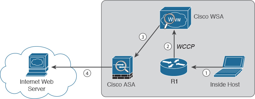
The following are the steps illustrated in Figure 6-24:
Step 1. An internal user makes an HTTP request to an external website.
Step 2. The internal router (R1) redirects the web request to the Cisco WSA using WCCP.
Step 3. The Cisco WSA connects to the website on behalf of the internal user.
Step 4. Also in this example, the firewall (Cisco ASA) is configured to only allow outbound web traffic from the WSA. The web traffic is sent to the Internet web server.
Figure 6-25 demonstrates how the WCCS registration works. The Cisco WSA is the WCCP client, and the Cisco router is the WCCP server.

During the WCCP registration process, the WCCP client sends a registration announcement (“Here I am”) every 10 seconds. The WCCP server (the Cisco router in this example) accepts the registration request and acknowledges it with an “I See You” WCCP message. The WCCP server waits 30 seconds before it declares the client as “inactive” (engine failed). WCCP can be used in large-scale environments. Figure 6-26 shows a cluster of Cisco WSAs, where internal Layer 3 switches redirect web traffic to the cluster.

The Cisco WSA comes in different models. The following are the different Cisco WSA models:
![]() Cisco WSA S680: A high-performance WSA designed for large organizations with 6,000 to 12,000 users. A two rack-unit (RU) appliance with 16 (two octa core) CPUs, 32 GB of memory, and 4.8 TB of disk space.
Cisco WSA S680: A high-performance WSA designed for large organizations with 6,000 to 12,000 users. A two rack-unit (RU) appliance with 16 (two octa core) CPUs, 32 GB of memory, and 4.8 TB of disk space.
![]() Cisco WSA S670: A high-performance WSA designed for large organizations with 6,000 to 12,000 users. A two RU appliance with 8 (two octa core) CPUs, 8 GB of memory, and 2.7 TB of disk space.
Cisco WSA S670: A high-performance WSA designed for large organizations with 6,000 to 12,000 users. A two RU appliance with 8 (two octa core) CPUs, 8 GB of memory, and 2.7 TB of disk space.
![]() Cisco WSA S380: Designed for medium-sized organizations with 1,500 to 6,000 users. A two RU appliance with six (one hexa core) CPUs, 16 GB of memory, and 2.4 TB of disk space.
Cisco WSA S380: Designed for medium-sized organizations with 1,500 to 6,000 users. A two RU appliance with six (one hexa core) CPUs, 16 GB of memory, and 2.4 TB of disk space.
![]() Cisco WSA S370: Designed for medium-sized organizations with 1,500 to 6,000 users. A two RU appliance with four (one quad core) CPUs, 4 GB or memory, and 1.8 TB of disk space.
Cisco WSA S370: Designed for medium-sized organizations with 1,500 to 6,000 users. A two RU appliance with four (one quad core) CPUs, 4 GB or memory, and 1.8 TB of disk space.
![]() Cisco WSA S170: Designed for small to medium-sized organizations with up to 1,500 users. A one RU appliance with two (one dual core) CPUs, 4 GB of memory, and 500 GB of disk space.
Cisco WSA S170: Designed for small to medium-sized organizations with up to 1,500 users. A one RU appliance with two (one dual core) CPUs, 4 GB of memory, and 500 GB of disk space.
The Cisco WSA runs Cisco AsyncOS operating system. The Cisco AsyncOS supports numerous features that will help mitigate web-based threats. The following are examples of these features:
![]() Real-time antimalware adaptive scanning: The Cisco WSA can be configured to dynamically select an antimalware scanning engine based on URL reputation, content type, and scanner effectiveness. Adaptive scanning is a feature designed to increases the “catch rate” of malware that is embedded in images, JavaScript, text, and Adobe Flash files. Adaptive scanning is an additional layer of security on top of Cisco WSA Web Reputation Filters, which include support for Sophos, Webroot, and McAfee.
Real-time antimalware adaptive scanning: The Cisco WSA can be configured to dynamically select an antimalware scanning engine based on URL reputation, content type, and scanner effectiveness. Adaptive scanning is a feature designed to increases the “catch rate” of malware that is embedded in images, JavaScript, text, and Adobe Flash files. Adaptive scanning is an additional layer of security on top of Cisco WSA Web Reputation Filters, which include support for Sophos, Webroot, and McAfee.
![]() Layer 4 traffic monitor: Used to detect and block spyware. It dynamically adds IP addresses of known malware domains to database of sites to block.
Layer 4 traffic monitor: Used to detect and block spyware. It dynamically adds IP addresses of known malware domains to database of sites to block.
![]() Third-party DLP integration: Redirects all outbound traffic to a third-party DLP appliance, allowing deep content inspection for regulatory compliance and data exfiltration protection. It enables an administrator to inspect web content by title, metadata, and size and to even prevent users from storing files to cloud services, such as Dropbox, Google Drive, and others.
Third-party DLP integration: Redirects all outbound traffic to a third-party DLP appliance, allowing deep content inspection for regulatory compliance and data exfiltration protection. It enables an administrator to inspect web content by title, metadata, and size and to even prevent users from storing files to cloud services, such as Dropbox, Google Drive, and others.
![]() File reputation: Using threat information from Cisco Talos. This file reputation threat intelligence is updated every 3 to 5 minutes.
File reputation: Using threat information from Cisco Talos. This file reputation threat intelligence is updated every 3 to 5 minutes.
![]() File sandboxing: If malware is detected, the Cisco AMP capabilities can put files in a sandbox to inspect its behavior, combining the inspection with machine-learning analysis to determine the threat level. Cisco Cognitive Threat Analytics (CTA) uses machine-learning algorithms to adapt over time.
File sandboxing: If malware is detected, the Cisco AMP capabilities can put files in a sandbox to inspect its behavior, combining the inspection with machine-learning analysis to determine the threat level. Cisco Cognitive Threat Analytics (CTA) uses machine-learning algorithms to adapt over time.
![]() File retrospection: After a malicious attempt or malware is detected, the Cisco WSA continues to cross-examine files over an extended period of time.
File retrospection: After a malicious attempt or malware is detected, the Cisco WSA continues to cross-examine files over an extended period of time.
![]() Application visibility and control: Allows the Cisco ASA to inspect and even block applications that are not allowed by the corporate security polity. For example, an administrator can allow users to use social media sites like Facebook but block micro-applications such as Facebook games.
Application visibility and control: Allows the Cisco ASA to inspect and even block applications that are not allowed by the corporate security polity. For example, an administrator can allow users to use social media sites like Facebook but block micro-applications such as Facebook games.
Cisco Content Security Management Appliance
Cisco Security Management Appliance (SMA) is a Cisco product that centralizes the management and reporting for one or more Cisco ESAs and Cisco WSAs. Cisco SMA consistent enforcement of policy, and enhances threat protection. Figure 6-27 shows a Cisco SMA that is controlling Cisco ESA and Cisco WSAs in different geographic locations (New York, Raleigh, Paris, and London).

The Cisco SMA comes in different models. These models are physical appliances or the Cisco Content Security Management Virtual Appliance (SMAV). The following are the different Cisco SMA models:
![]() Cisco SMA M680: Designed for large organizations with over 10,000 users
Cisco SMA M680: Designed for large organizations with over 10,000 users
![]() Cisco SMAV M600v: Designed for large enterprises or service providers
Cisco SMAV M600v: Designed for large enterprises or service providers
![]() Cisco SMA M380: Designed for organizations with 1,000 to 10,000 users
Cisco SMA M380: Designed for organizations with 1,000 to 10,000 users
![]() Cisco SMAV M300v: Designed for organizations with 1,000 to 5,000 users
Cisco SMAV M300v: Designed for organizations with 1,000 to 5,000 users
![]() Cisco SMA M170: Designed for small businesses or branch offices with up to 1,000 users
Cisco SMA M170: Designed for small businesses or branch offices with up to 1,000 users
![]() Cisco SMAV M100v: Designed for small businesses or branch offices with up to 1,000 users
Cisco SMAV M100v: Designed for small businesses or branch offices with up to 1,000 users
Cisco Cloud Web Security
Cisco Cloud Web Security (CWS_ is a cloud-based security service from Cisco that provides worldwide threat intelligence, advanced threat defense capabilities, and roaming user protection. The Cisco CWS service uses web proxies in Cisco’s cloud environment that scan traffic for malware and policy enforcement. Cisco customers can connect to the Cisco CWS service directly by using a proxy autoconfiguration (PAC) file in the user endpoint or through connectors integrated into the following Cisco products:
![]() Cisco ISR G2 routers
Cisco ISR G2 routers
![]() Cisco ASA
Cisco ASA
![]() Cisco WSA
Cisco WSA
![]() Cisco AnyConnect Secure Mobility Client
Cisco AnyConnect Secure Mobility Client
Organizations using the transparent proxy functionality through a connector can get the most out of their existing infrastructure. In addition, the scanning is offloaded from the hardware appliances to the cloud, reducing the impact to hardware utilization and reducing network latency. Figure 6-28 illustrates how the transparent proxy functionality through a connector works.
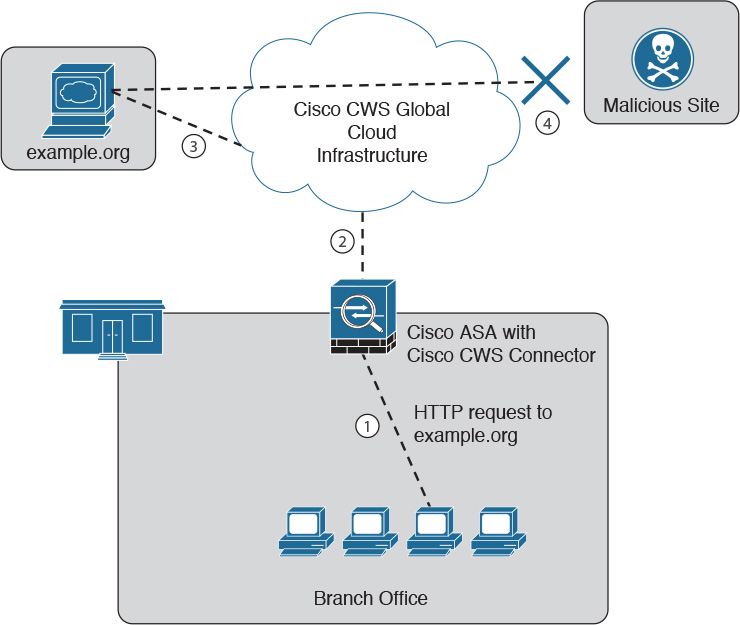
In Figure 6-28, the Cisco ASA is enabled with the Cisco CWS connector at a branch office. The following steps explain how Cisco CWS protects the corporate users at the branch office:
Step 1. An internal user makes an HTTP request to an external website (securemeinc.org).
Step 2. The Cisco ASA forwards the request to Cisco CWS global cloud infrastructure.
Step 3. It notices that example.org had some web content (ads) that was redirecting the user to a known malicious site.
Step 4. Cisco CWS blocks the request to the malicious site.
Cisco Identity Services Engine
The Cisco ISE is a comprehensive security identity management solution designed function as a policy decision point for network access. It enables security administrators to collect real-time contextual information from the network, its users, and devices. Cisco ISE is the central policy management platform in the Cisco TrustSec solution. It supports a comprehensive set of authentication, authorization, accounting (AAA), posture, and network profiler features into a single device.
Cisco ISE enables security administrators to provide network guest access management and a wide-ranging client provisioning policies, including 802.1X environments. The support of TrustSec features such as Security Group Tags (SGTs) and Security Group Access Control Lists (SGACLs) makes the Cisco ISE a complete identity services solution. Cisco ISE supports policy sets, which let a security administrator group sets of authentication and authorization policies.
Cisco ISE provides network access control (NAC) features, including posture policies to enforce that end-user devices are configured with the most up-to-date security settings or applications before they enter the network. The following agent types are supported by the Cisco ISE for posture assessment and compliance:
![]() Cisco NAC web agent: A temporary agent that is installed in end-user machines at the time of login. The Cisco NAC Web Agent is no longer visible on the end-user machine after the user terminates the session.
Cisco NAC web agent: A temporary agent that is installed in end-user machines at the time of login. The Cisco NAC Web Agent is no longer visible on the end-user machine after the user terminates the session.
![]() Cisco NAC agent: Installed (permanently) on a Windows or Mac OS X client system.
Cisco NAC agent: Installed (permanently) on a Windows or Mac OS X client system.
![]() AnyConnect ISE agent: Installed (permanently) on a Windows or Mac OS X client system.
AnyConnect ISE agent: Installed (permanently) on a Windows or Mac OS X client system.
Cisco ISE provides a comprehensive set of features to allow corporate users to connect their personal devices, such as mobile phones, tablets, laptops, and other network devices to the network. This is what is called bring your own device (BYOD). BYOD introduces many challenges when protecting network services and enterprise data. Cisco ISE provides support for multiple Mobile Device Management (MDM) solutions to enforce policy on endpoints. ISE can be configured redirect users to MDM onboarding portals, prompting them to update their device before they can access the network. Cisco ISE can also be configured to provide Internet-only access to users who are not compliant with MDM policies.
Cisco ISE supports the Cisco Platform Exchange Grid (pxGrid). Cisco pxGrid is a multivendor, cross-platform network system that combines different parts of an IT infrastructure, such as the following:
![]() Security monitoring
Security monitoring
![]() Detection systems
Detection systems
![]() Network policy platforms
Network policy platforms
![]() Asset and configuration management
Asset and configuration management
![]() Identity and access management platforms
Identity and access management platforms
Cisco pxGrid has a unified framework with an open application programming interface (API) designed in a hub-and-spoke architecture. pxGrid is used to enable the sharing of contextual-based information from Cisco ISE session directory to other policy network systems such as Cisco IOS devices and the Cisco ASA.
The Cisco ISE can be configured as a certificate authority (CA) to generate and manage digital certificates for endpoints. Cisco ISE CA supports standalone and subordinate deployments.
Cisco ISE software can be installed on a range of physical appliances or on a VMware server (Cisco ISE VM). The Cisco ISE software image does not support the installation of any other packages or applications on this dedicated platform.
Summary
The Cisco CTD Solution uses Cisco next-generation security products and components, in addition to NetFlow and the Lancope StealthWatch System, for broad network visibility in the attack continuum. This chapter provided an introduction to the attack continuum and the deployment and configuration of NetFlow in key Cisco products such as the Cisco ASA, Cisco NX-OS devices, and the Cisco NGA. Previous chapters covered the NetFlow configuration in Cisco IOS-XE and classic Cisco IOS devices. This chapter also covered the Cisco FirePOWER and FireSIGHT, and Cisco’s AMP for endpoint control and network malware control with AMP for networks. It also provided an overview of the content security appliances and services such as the Cisco WSA and Cisco CWS, which provide adaptive threat control of web traffic, in addition to the Cisco ESA, which provides dynamic threat control for email traffic. At the end of the chapter, the Cisco ISE was introduced. The Cisco ISE is used in the Cisco CTD Solution for user and device identity integration with Lancope StealthWatch and remediation policy actions using pxGrid.