USB Architecture
In a USB system, the host controller is the master and the USB devices are the subordinates. The USB topology is organized in a tree-like structure, which forms a bus, with the host controller being the root and the controller of the subordinated device. The host controller is responsible for coordinating activities on the bus, and a device is not able to perform I/O, or any other activity on the bus, without first being asked to do so by the host.
The tree structure branches out with the help of hubs, which allow connected devices to become part of the bus, and thus extend it, as a new branch. The subordinate devices of a hub can have other hubs connected to them— up to four levels deep is possible. The root hub is usually embedded into, and part of, the host controller itself. Figure 8-1 shows the USB topology for a MacBook computer.
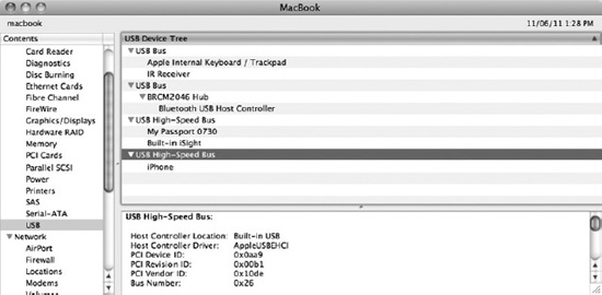
Figure 8-1. System Information showing the USB topology of a MacBook, with external devices connected
The system in Figure 8-1 has four built-in USB buses, but only two buses are actually connected to external USB ports. While most people associate USB devices with external devices, USB is often used to communicate with fixed internal devices in the computer system. The first two USB buses of the MacBook in Figure 8-1 are internal to the notebook, and are used to connect to the internal keyboard, the trackpad, and the IR Receiver. The second internal bus connects to the Bluetooth USB host controller. Both of these buses are USB 1.1 buses, which is fine because the devices connected to them all have low bandwidth requirements.
This MacBook has two external USB devices connected, an external hard drive and an iPhone, each connected to a separate physical USB port on the system. Although you would think that an external USB port has its own dedicated bus, this may not always be the case. As you can see in Figure 8-1, one of the buses has an additional USB device attached to it, namely the built-in iSight camera. The camera requires more bandwidth than the 1.1 USB buses/controllers can provide, so it is instead attached to one of the two USB 2.0 controllers, likely to avoid having a separate controller just for the iSight, saving space, parts, cost, and battery power. The downside is that an external device will share bandwidth with the iSight camera (when it is in use).
The exact USB topology will vary from system to system, and this is just one example of how it can be organized.
Each bus in a USB system can support up to 127 devices, including hub devices, which are also USB devices. Bandwidth on a USB bus is shared between the connected devices, so having a large number of active devices will incur a significant penalty, which is why it is now common to have physical USB ports on separate host controllers—each providing a bus, rather than having ports connected to a single controller.
A USB is designed to be hot-pluggable, which means that the system can handle the insertion or removal of any device at any time during operation, although, depending on the type of device, this may not necessarily be safe to do—the prime example is a hard drive, which, if unplugged at the wrong time, can lead to corruption of the drive's file system. From a developer's perspective, this means that your driver code needs to be designed to anticipate the arrival or removal of a device.
The USB specification also supports power for devices through the bus, a major advantage over older bus technologies, as this, for example, will allow you to charge an iPhone simply by plugging it in to your laptop, or to self-power a device such as a hard drive.
The key characteristics of the USB can be summarized as follows:
- Single connector type for all devices, designed to replace a variety of older connectors, such as the PS/2.
- Ability to connect many devices to the same connector.
- USB buses can be expanded with the help of hubs, supporting up to 127 devices per bus.
- Devices are hot-pluggable.
- Devices can be powered by the bus, which enables them to be charted or fully powered through the bus, depending on power requirements.
- Bandwidth is shared between devices on a bus.
- A USB device is a slave device and cannot initiate any activity on the bus without the permission of the host.
One key characteristic that sets the USB apart from traditional hardware architectures, such as the PCI, is that it does not directly generate system interrupts. The ability for a device to asynchronously notify the system of some event is essential for the operation of many types of common devices—for example, a network device that will notify the system each time a new network packet arrives, or a mouse or keyboard that relies on telling the system its current position or which key was pressed.
A USB device can still provide interrupt-like capabilities, but it is not able to directly interrupt a CPU in the same way that a PCI device can. To receive an interrupt from a USB device, an interrupt transfer has to be issued to the device. Once the transfer is issued, and an event occurs, such as the arrival of a network packet, the USB device is not simply free to signal the host controller—it has to be polled by the host controller. A USB device can only interact on the bus if told to do so by the host. The host controller provides a maximum latency guarantee for interrupt transfers. The lowest achievable latency is 125 microseconds. A device can specify the desired interval for interrupt polling in its endpoint descriptors.
It should be noted that although a USB device cannot directly interrupt a CPU itself, a USB host controller certainly can, and may do so in response to a completed interrupt transfer from a device. Most modern computer systems talk to USB controllers via PCI.
![]() Tip The USB specifications are governed by the USB Implementers Forum (USB-IF), a not-for-profit organization. Their website can be found at
Tip The USB specifications are governed by the USB Implementers Forum (USB-IF), a not-for-profit organization. Their website can be found at http://www.usb.org.
USB Transfer Speeds
The first iteration of the USB standard supported two speeds: a low speed, at 1.5 Mbit/s, and a full speed, at 12 Mbit/s. Low speed devices are less susceptible to electromagnetic interference, and therefore these can be made cheaper, as they can be created using lower quality parts. This reduces the cost of simpler USB devices, which do not require the additional bandwidth needed for a full speed device. The USB 2.0 standard included the full speed mode, capable of operating at speeds up to 480 Mbits/s, while also being backward compatible with USB 1.0. This made the USB competitive with the Firewire specification, which at the time operated at 400 Mbits/s (see Table 8-1 for USB transfer speeds).
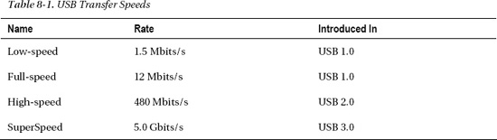
The USB 3.0 specification supports speeds up to 5 Gbits/s, and it was the fastest generally available external bus until Thunderbolt was released in 2011. Apple has so far not opted to include USB 3.0 compatible devices in its computers, although there are third party offerings available for Macs that support ExpressCard or PCI-Express.
Host Controllers
Host controllers are governed by separate specifications that determine how the computer system will communicate with the host controller. Modern systems typically embed the USB host controller on the motherboard's I/O controller (south bridge). Most host controllers have a PCI interface that is used by the system for communication with the controller. When a driver talks to a USB device, it does not do so directly—it talks to the host controller over PCI, although to the driver it looks as if it is communicating with the device directly, due to the object-oriented abstraction layer provided by the I/O Kit. The USB does not generate interrupts directly; however, the host controller uses both DMA and interrupts.
Typically, a 32-bit x86 system has only 16 interrupt lines, and often as few as 2–3 interrupt lines, available for use by external peripherals. The USB solves this problem, as the computer system needs only a single interrupt line to the USB host controller to communicate with all of the devices connected to the controller. The USB specifications standardize the way in which a host communicates with a USB device; however, there are several standards for how a computer system communicates with a host controller:
- Universal Host Controller Interface (UHCI): UHCI was developed by Intel. The UHCI specification supports USB 1.x devices at low and full speed.
- Open Host Controller Interface (OHCI): OHCI was developed by Microsoft and Compaq, among others, also for USB 1.x devices. The OCHI controller is smarter than UHCI, in that it has more logic embedded in the controller itself, as opposed to UHCI, which is simpler on a hardware level, but requires a more complicated host controller driver in the OS.
- Enhanced Host Controller Interface (EHCI): EHCI was created for USB 2.0 and supports 480 Mbits/s high-speed devices. The EHCI does not handle USB 1.x devices, so it needs to incorporate a UCHI- or OHCI-based controller to handle devices based on the 1.x series of specifications.
- Extensible Host Controller Interface (xHCI): xHCI was designed by Intel and supports the USB 3.0 specification. It was designed as a unified host controller, making EHCI, OHCI, and UHCI redundant.
It is not uncommon for a computer system to have several host controllers, each supporting a different host controller interface. For example, the MacBook in Figure 8-1 has two OHCI controllers and two EHCI controllers for USB 2.0 support. Mac OS X presently has controller drivers to support OCHI, UHCI, and EHCI, but not xHCI.
The USB Protocol
Unlike serial port devices, where there are no protocols (it's up to the application to implement one) and just streams of bits and bytes, the USB has a packet-based protocol. This is necessary as the bus is shared and there can be many devices connected to it, which has to be individually addressed. Unless you are a hardware engineer programming the firmware for a USB device, you don't really need to understand, or even know about, the specifics of how this communication occurs, but it may be helpful, in some cases, to have a basic understanding of how the communication happens at the protocol level, in order to debug problems.
The USB protocol is implemented between the host controller and the device, and it determines how data is transferred on the bus. A driver does not really have insight or influence over this process, as the details are handled by the electronics of the host and the device, and not the driver—unlike with networking, where many aspects of the communication protocol are under software control. In order to see or intercept what is actually crossing the wire, a USB packet analyzer is needed. A USB analyzer is a specialized (usually very expensive) device that can be connected between the device and the host to capture the traffic between them.
USB packets consist of 8-bit words in little-endian format (LSB). The USB protocol has four main packet types:
- Token packet: This acts a header, and tells the recipient what type of packet/data follows. The three types of token packets are IN, OUT, and Setup. The first two specify the direction of the packet and the last is used to initiate a control transfer. The direction is seen from the host side, so IN means a transfer from the device to the host, and OUT means a transfer from the host to the device.
- Data packet: This can carry arbitrary data, with 0–1024 bytes per data packet.
- Handshake packet: This is sent to acknowledge the successful (ACK) or unsuccessful (NAK) delivery of a packet, as well as to report stalls (STALL).
- Start of Frame packet: This is sent at regular intervals to synchronize data flow for isochronous transfer modes.
The layout of each packet type can be seen in Figure 8-2.
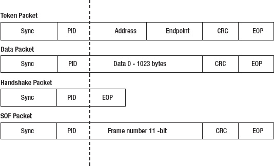
Figure 8-2. Layout of USB packet types
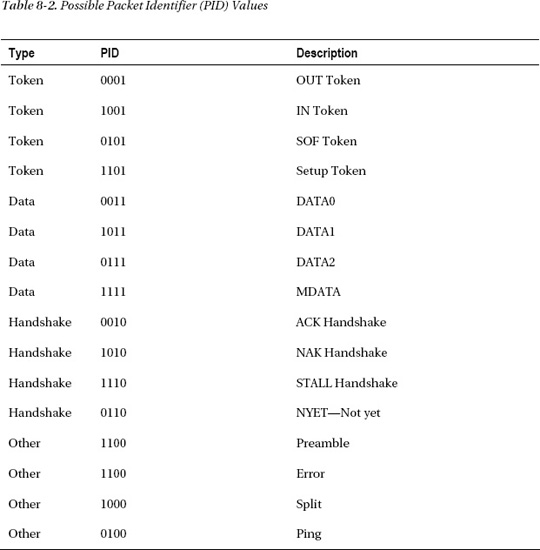
All USB packets start with the sync and PID (packet identifier) fields. The sync field precedes other data and can be used by the receiver for clock synchronization. The field is 8-bits for low and full speed devices, and 32-bits for high-speed devices. The PID (packet identifier) field allows the decoder to determine the packet type that follows it. Possible values for the PID field are shown in Table 8-2. The PID is 4-bits wide, though it is 8-bits in total. The last four bits are a check field containing a complement of the first four bits, which helps determine if the packet is valid and has not been corrupted.
Token packets are used for addressing a specific device. The address field specifies which device the packet is to or from, and is a number from 1–127, which addresses the device on the bus. A USB device may have several endpoints, which are independent communication channels, and the endpoint field specifies to which endpoint on a device the packet will be delivered. Endpoints are discussed later in this chapter.
All packet types have a CRC (Cyclic Redundancy Check—used to verify the integrity of the data) field. All packet types have a CRC field that is 5-bits wide, except data packets, which instead have a wider 16-bit CRC field.
The end of packet (EOP) field is used as a delimiter.
A USB transaction can consist of up to three data packets. Data packets are indicated by the PID field and can be one of the following: DATA0, DATA1, DATA2, and MDATA, though the latter two are used only for isochronous transfer modes. The PID field determines which of the data packets are transmitted, as shown in Table 8-2.
A data transfer from the host to a device might look like this:
- Token Packet containing the address of the device and the endpoint. PID indicates an OUT transfer.
- Data 0 Packet containing 1024 bytes of payload data.
- Data 1 Packet containing 322 bytes of payload data.
- Handshake Packet sent from the device to the host indicating the status of the transfer, such as ACK, NAK, or STALL.
Endpoints
Communication between a host controller and a USB device is based on the concept of endpoints. An endpoint is uni-directional, and the direction is either IN or OUT—that is, communication from the device to the host, or communication from the host to the device. The connection from a host controller to an endpoint is referred to as a pipe. There are two types of pipes: a stream pipe, which carries data, and a message pipe, which carries control requests. A USB device can support up to 32 endpoints, with a maximum of 16 IN endpoints and 16 OUT endpoints. Endpoint address 0 is special, reserved for device configuration. There are four different types of endpoints available:
- Bulk endpoints: These are used for transferring large amounts of data. Bulk transfers offer no guarantees about timely delivery or bandwidth, but do offer guaranteed delivery and error detection. Bulk transfers are not available for low speed modes. Hard drives, scanners, printers, and network cards typically use bulk transfers.
- Control endpoints: These are used for device configuration and status retrieval. Requests to a control endpoint are guaranteed delivery by using reserved bandwidth.
- Interrupt endpoints: These are intended for exchanging small amounts of time-sensitive data with guaranteed delivery.
- Isochronous endpoints: These provide guaranteed bandwidth, but not guaranteed delivery. Data is not re-sent if it is lost, which is ideal for video and audio applications.
USB Descriptors
A USB descriptor is used to describe a device's capabilities, type, requirements, and more. Descriptors are organized in a hierarchy consisting of the following main descriptor types:
- Device Descriptor: This contains the product ID (idProduct) and vendor ID (idVendor) of the USB device. There is only one device descriptor per device. It also contains information on how many descriptors follow it. Both the vendor ID and product ID are 16-bit integers. The vendor ID is assigned by the USB-IF. A vendor can choose any 16-bit value for the product ID. The vendor/product ID combination must be unique to avoid problems, as they are used to determine the correct drivers for a device. The device descriptor also contains two fields to indicate the type of device: bDeviceClass and bDeviceSubClass.
- Configuration Descriptor: This specifies an alternate configuration in which a device can operate. For example, a device might have two configurations: one configuration when it is self-powered and one configuration when it is bus-powered. The latter can operate in a limited mode that only allows a subset of overall functionality, or perhaps only provide the ability to program the device's firmware. Only one configuration can be active at any given time. The configuration descriptor may have several interfaces underneath it, and it is uncommon for a device to have more than one configuration descriptor.
- Interface Descriptor: This is a collection or group of endpoints that together perform a function. It can be useful to think of it as a logical subdevice. An interface may have zero or more endpoints. For example, in Figure 8-3, we see a multifunction USB device, which contains two interfaces: interface #0 is a printer, while interface #1 is a scanner device. Multiple interfaces may be active and operate simultaneously. Just like the device descriptor, the interface descriptor has fields to indicate the class of interface, which is given by bInterfaceClass and bInterfaceSubClass.
- Endpoint Descriptor: This describes the type (bulk, interrupt, isochronous, or control) and the direction (IN, OUT) of an endpoint.
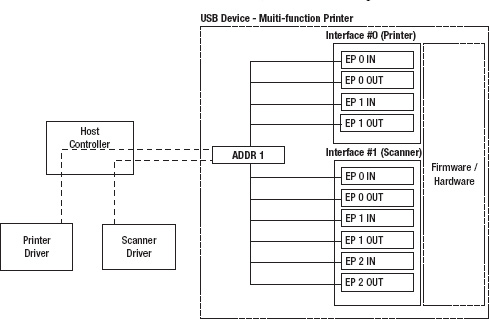
Figure 8-3. USB compound device with two interfaces
USB Device Classes
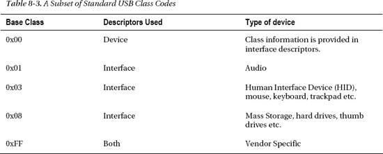
The USB descriptors contain class codes, which identify the class of a device to the system and can be used to identify the appropriate driver to load for the device. The class code may be specified in the device descriptor, the interface descriptor, or both. A class code of 00h specified in the device descriptor means that the actual class code should be read from the interface descriptors instead. There is also a subclass field that further narrows down the type of device. Table 8-3 shows a small subset of available class codes.
Many operating systems, including Mac OS X and iOS, provide default drivers for devices that conform to the standard classes, and therefore the OS can handle any mass storage or audio USB device without having to install a third party driver. It is still possible for a vendor to supply an optional driver for devices that provide additional capabilities not found in the generic driver supplied by the OS. For this, the I/O Kit matching system can be used to ensure that the more specific driver is matched, rather than the default driver.
![]() Tip The full list of class codes, as well as more detailed descriptions, can be found at
Tip The full list of class codes, as well as more detailed descriptions, can be found at http://www.usb.org/developers/defined_class.