
5
Analysis and Design Methodologies
LEARNING OBJECTIVES
At the end of this chapter, you should be able to understand and use techniques and methods regarding
Various methodologies of system development.
Complete life cycle development phases in a software development project.
Structured analysis and design, including function modelling and data modelling.
Data flow diagrams and data dictionaries and entity relation.
5.1 Introduction
Detailed and in-depth analysis of issues involved in a system under development or an existing system would lead to better understanding and thus better designed systems meeting user requirements in letter and spirit. If we can model analysis and design phases using the latest tools like UML, software development will be in consonance with pacifications and thus greatly enhance the productivity of developers and designers.
In this chapter, we cover details like software development life cycle and design methodologies that include in-depth coverage of structured analysis and design as well as object-oriented analysis and design. We present theoretical foundation as well as case studies so that you can grasp the concepts. We have also included elaborative examples and assignments at the end of the chapter. There are programmers and programmers. But there are only a handful of competent designers. Thus, this chapter is important for budding analysts and engineers.
5.2 Stages and Methodologies for Systems Development
A complex project involves clearly two major stages: analysis and design phases. The project development team goes through the following stages in project implementation spread over analysis and design phases:
- Inception: This initial stage is used to elicit information from the users regarding the problem and estimation of project costs and the formation of a senior project team.
- Elaboration: This is under the analysis phase and is used to elaborate the analysis carried out during the initial stages. Estimations and conceptual understanding of the project is undertaken. Tools like UML and CASE are employed at this stage.
- Construction: This stage falls under the design stage wherein design methodologies like structured design (SD) or object-oriented design (OOD) are resorted. This section also includes coding the system as per design.
- Coding: This stage is about translating the design into coding using a structural language like C or object-oriented language like C++ or Java based on the methodology of development.
- Testing and Delivery and Deployment: The project developed undergoes elaborate testing to check if the requirements are met. The testing is also carried out after delivery of the project at the users’ site. Testing methods depend on the methodology chosen like structural analysis and design (SASD) or object-oriented analysis and design (OOAD).
5.2.1 Methodologies for Software Development
There are many methodologies for the development of information systems: systems development life cycle (SDLC) and OOD are widely used and popular design methodologies.
5.2.2 Systems Development Life Cycle (SDLC)
SDLC is closely linked to structured system analysis and design (SASD). SDLC is also referred to as waterfall model.
It is called waterfall model because it looks like one. It is a model that describes the steps taken in the development of information systems. This concept has been introduced by Mr Horner in 1993.
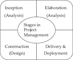
Figure 5.1 Stages in project
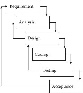
Figure 5.2a SDLC – waterfall model
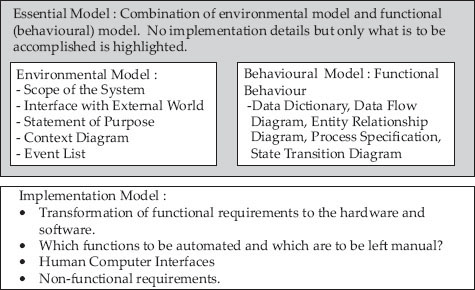
Figure 5.2b Structured analysis and design – main elements
The series of action and steps to be taken and deliverables at each step are shown below:
- Problem definition: The user would have prepared a problem narrative. On receiving a request from the user for systems development, an investigation is conducted to state the problem to be solved. Deliverables: Problem statement.
- Feasibility study: To define the scope and objective of software project study and also establish alternative solutions available. Deliverables: Feasibility report.
- Systems analysis phase: Analysis of existing system. How and what it does. Deliverables: Specifications of the present system.
- Systems design phase: Study of specifications and preparation of a specifications document showing what else needs to be done to obviate the shortcomings of the existing system. Deliverables: Specifications of the proposed system.
- Systems design: Development of code, user manuals. Deliverables: Programs, their documentation and user manuals.
- System testing and evaluation: Testing, verification and validation of the system against specifications. Deliverables: Test and evaluation results, and the system ready to be delivered to the user/client.
The advantages of the waterfall model are as follows:
- Clearly defined deliverables at the end of each phase, so that the client can take decisions on continuing the project.
- Resources can be committed incrementally and not all at once.
- Problems can be detected early in the developmental stage.
- Detailed stagewise documentation.
The disadvantages of the waterfall model are as follows:
- The project needs to be committed. It is not an incremental model.
- Problems have to be detected early. Later stage detection means huge costs.
5.3 Structured Analysis and Design (SASD)
SASD is a methodology adopted to analyse the business model and convert it into specifications, which in turn will be modified into computer programs, hardware and/or manual procedures. SASD as a methodology was developed in the late 1970s by DeMarco, Yourdon and Constantine after the emergence of structured programming. The purpose of SASD is to develop a useful, high-quality information system that will meet the needs of the end user. CASE tools are graphical tools to implement SASD techniques and have now become industry standard for developing SASD models.
Elements of Structural Analysis and Design:
The steps involved in SASD are as follows:
STEP 0: Statement of Purpose
This is a clear and concise statement highlighting the purpose of the system. It is meant for higher management as a concept document and cannot be used for development of the system.
Example of statement of purpose – The purpose of the “Agri Card System” is to provide a methodology for the bank to extend credit to the farmer. The system will handle details of credit application, loan management, billing, recovery and management reporting. The steps involved are:
STEP 1: Draw the context diagram to define the scope of the project. This diagram is like a block diagram, showing the system as a whole with set of inputs and outputs and a transformation system. The objective of a system context diagram is to focus attention on external factors and events that should be considered in developing a complete set of system requirements and constraints. In Figure 5.7, we have provided a context diagram for Student Smart Card Application.
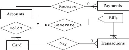
Figure 5.7 ERD for credit card system
STEP 2: This is documentation showing how the existing system works. It is accomplished by drawing the physical data flow diagrams (DFDs) of the existing system that specify its current implementation. The key questions raised are:
- Who performs what tasks?
- How and when are they performed and what is their frequency of performance?
- How and where is the data stored?
STEP 3: This stage is for documentation of the proposed system. It is about what the proposed system will achieve. The system designer will study the lacunae of existing system and propose the modified system in the form of logical DFDs.
STEP 4: At this stage, logical DFDs at STEP 3 are converted to physical DFDs by examining which implementation meets the criteria. Who will perform the various tasks?
- Who performs what tasks?
- How and when are they performed and what is their frequency of performance?
- How and where is the data stored?
5.3.1 Conceptual Design – Functional Modelling and Data Modelling
Conceptual design consists of data modelling and functional Modelling. Data modelling is a technique to organize the data and functional modelling (also called process modelling) is a technique to document systems process, inputs and outputs. Conceptual design phase throws up answers to questions such as
- What are the processes making up the proposed system?
- What data is used in each process?
- What are the inputs?
- What are the outputs?
5.3.2 Modular Design
The proposed system is broken into small independent subsystems called modules. These modules are designed and coded separately and are later combined with other modules to provide complete functionality of the proposed system. We will adopt a top-down hierarchical model in which higher-level modules will have larger scope and lower-level modules will have smaller scope. The design considerations for breaking in to modules are:
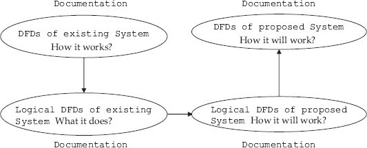
Figure 5.3 DFDs of existing and proposed system
- The size of the module as indicated by lines of code should be small.
- The modules must be sharable so as to avoid duplication.
5.3.3 Analysis and Design Techniques and Tools
The analysis part will involve converting business model into data flow and control flow. This is achieved through the use of DFDs. Data dictionaries are essential to describe the data and control flows. DFDs are graphical representations of the functional decomposition of the main process involved. Process specifications and specifying operations are helpful in decomposing into cohesive submodules with coupling between functions leading to structured data. These subdivided systems in turn retain constraints and specification of originally designed system. SASD technique attempts to solve the complex problem by dividing large, complex problems into smaller, more easily handled ones. The technique can be called the “divide and conquer method.” The approach adopted can also be called the “top-down approach.” The functional decomposition of the structured method describes the process without delineating system behaviour and dictates system structure in the form of required functions. The method identifies inputs and outputs as related to the activities. The result of structured analysis is a set of related graphical diagrams, process descriptions and data definitions. They describe the transformations that need to take place and the data required to meet a system's functional requirements.
5.3.4 Context Diagrams
This diagram is like a block diagram, showing the system as a whole with a set of inputs and outputs and a transformation system. The objective of a system context diagram is to focus attention on external factors and events that should be considered in developing a complete set of system requirements and constraints. We have provided an example of context diagram along with a case study in Figure 5.7.
Purpose
- Highlights the boundary between the system and the outside world
- Highlights the people, organizations and outside systems that interact with the system under development
- Special case of the data flow diagram
Context Diagram – Notation
![]() Process – Represents the proposed system
Process – Represents the proposed system ![]() Flow. Data in/out
Flow. Data in/out
![]() Terminator – Represents the external entities
Terminator – Represents the external entities
5.3.5 Event List
The purpose of event list is to prepare a list of external events/activities to which system under design should respond. This is similar to use cases of OOAD methodology. The events can be classified as
- Event triggered by incoming data
- Internally generated event
- External unpredictable event
The examples for event list are:
- Student completes registration process
- Customer pays credit card bill
5.3.6 Data Flow Diagrams
Data flow diagrams (DFDs) also called data flow graphs are used in the analysis phase as they are useful in understanding a system and can be effectively used during analysis. A DFD views function as data flows through the system. DFDs highlight the data transformation from input stage to output stage through various processes.
Example 5.1: DFD for Issue of Grade Card for Student
We will show the DFD for preparing students’ grade sheet. We will call this system as GradePrep system, as shown in Figure 5.5. In GradePrep, inputs and outputs are:
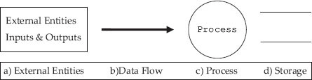
Figure 5.4 Symbols in DFD
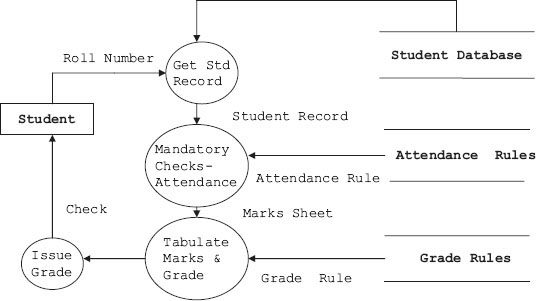
Figure 5.5 DFD for issue of grade sheet to a student
- Students personal data base which stores basic information about student such as name, roll number, marks obtained in subjects and attendance details.
- Grade Rule database would store information about criteria for calculating grades and Attendance Rule database contains rules regarding mandatory attendance required to declare the result, etc.
- Students’ grade sheet is output.
5.3.7 Data Dictionary
A data dictionary or database dictionary is a file that defines the database. A database dictionary contains
- List of all files and tables in the database.
- The number of records in each file.
- Names and types of each data field.
Data dictionary only maintains information to manage data but holds no actual data. Database management system cannot function without data dictionary. We can call it meta data about data but not actual data. In the DFD shown above, we have used terms like student database, attendance rules, grade rule, etc. But what exactly is the structure of data in these storage spaces. Data dictionary defines data structure in these storage spaces:
  • Student Record = roll number + Name + course + Semester + marks1 + marks2 + marks3 + marks 4 + marks 5 + Attendance percentage
  • Attendance rule: if (attendance > 75) eligible = 1 else eligible = 0
  • Marks Sheet: roll number + Name + course + Semester + marks1 + marks2 + marks3 + marks 4 + marks 5 + Total Marks + Grade
  • Roll Number: digit + digit + digit + digit + digit (As many digits as there are in roll number)
  • Grade: String “A” or “B” or “C” or “D,” etc.
5.3.8 Multilevel DFDs
The DFD and data dictionary for the DFD are ready; we can expand the DFD into second and subsequent levels to understand the process involved better. For this study, let us consider the library information system (LIS) of a university or a college. Student selects a book for issue based on availability status checked online. The library staff has to process the request for issue, verify and validate the request, and process the request. Finally, the student is issued the book with issue authorization note and his account modified accordingly. Note that we have selected LIS for this case study because you are familiar with the workings of a library. We can easily replace the model with any other model like purchase–order system, etc. In Figure 5.6a, b, c, we have shown how a DFD can be expanded to gain insight into how an issue section of a library works. First, incoming issue requests are checked for correct book titles, authors’ names and other information. Student's entitlement is also checked at this stage by checking the students’ database. This process is elaborated at DFD level 2. Finally, the process of issue is elaborated at DFD level 3. We show the set of DFDs drawn for issue section of LIS in Figure 5.6a, b, c.
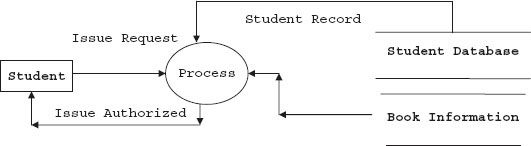
Figure 5.6a First-level DFD for issue of a book
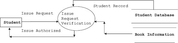
Figure 5.6b Second-level DFD – issue request verification
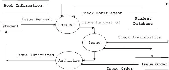
Figure 5.6c Issue request processing system
Level 1: General overall concept diagram
Level 2: Expand the process of level 1. At this level, we will check the request for issue and verify if the student is entitled to draw the book and further if the book can be issued.
Level 3: Expanding issue request processing system
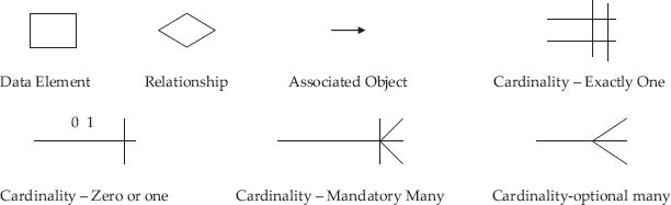
5.3.9 Entity Relationship Diagram
Entity is like an object. It is a thing present in the system under development. It is a graphical representation of the data layout of a system. It defines data elements and their interrelationships in the system.
Entity Relationship Diagram — Notation
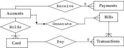
Let us study the ERD for the credit card system of a bank. The entities in this system are payments, bills, transactions, accounts, transaction elements. Relationships are:
- User pays for a transaction using card
- Accounts section hold card information
- Accounts generate bills
- Bills contain transactions
- Accounts receive payments
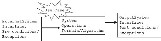
5.3.10 Process Specifications
Shows process details, which are not shown in a DFD. Input, output and algorithm of a module in the DFD are included in process specifications. Observe at each operation and define the transformation of inputs to outputs in the system functional model and the functional model. We desire to define the transformation in terms of computation, algorithms and formulas. Specifying operations is like specifying the attributes. Constraints will help the designer to develop the system as per specifications by ensuring one-to-one mapping of functionality, i.e. operations. Specifying operations is usually carried out in graphical modelling so that they define underlying constraints with precision. The net result is better designed systems. So when we intend to specify the operation, what are the areas we need to specify? They are:
- Internal behaviour: This can be specified both by algorithmic and non-algorithmic methods. The non-algorithmic approach refers to using decision tables and setting up of pre- and post-operation values. A transformation could be described as follows:
- A table showing the mapping from one object value to another
- A formula or equations showing the relationship between an input object value and an output object value
- A text description of the transformation
- Interface with external entities: Interfaces specify the inputs to the system. Specifications can be used as a means to check if functionality is meeting the requirements. In Figure 4.21, we presented the functional model as a system view with inputs, outputs and system transformations.
Operations can be classified as system operations and functional operations. System operations are those that affect the whole system. For example, withdrawal of cash from ATM would affect the entire system. Functional operations are local in nature and affect the attributes called by that particular module.
- Procedure for Specifying the System Operations and Function Operations.
- Identify all system/function operations
- For each system operation, state the system operation name, input objects (parameters), transformation and output objects (return values). In addition, state the system operation preconditions, post-conditions and exceptions.
- Prepare a system/function operation table, as shown below:

5.3.11 Specifying Constraints
Functional model can best be described by a graphical representation. Graphical representation is nothing but functional decomposition described in earlier sections, wherein two distinct paths, namely, control path and data path, flow from top to bottom covering all decomposed modules.
Therefore, all functionality constraints applied at the topmost level must also be applied to decomposed lower levels. For example, if reliability is a constraint of the topmost module, then it must also necessarily be a constraint in succeeding modules. Constraints and their implications are discussed next.
- Performance: Performance criteria are defined at the topmost layers. Performance dictates the operations. Operations, in turn, decide the functionality of the module. So when a top module is decomposed, care must be taken to ensure that operations at each submodule are as per specifications.
- Reliability: In software, reliability of function modules depend on the way the reliability aspect is distributed among the subdivided function modules and the way user interacts with these modules. There should be match between user operational profile and functional profile.
- Security: Security issues crop up because the user at operational level is able to exploit some functionality that is not part of the original top-level specification.
This loophole might have been created inadvertently at lower functional level. The criteria to be considered to plug these loopholes are described below:
- Access Control: Subdivision of functionality must ensure that only certain classes or users are able to initiate and use the functionality with authorization codes.
- Integrity of Data: The data is primacy and no unauthorized access can be allowed at submodules. A suitable encryption technique can solve these problems.
- Control of User Behaviour: Normal behaviour of a user of a function module must be specified and any deviations form this normal and designed process must be recognized by the module and further exploitation of function module must be denied.
- Availability: We are aware that user operations are distributed over submodules and users must be guaranteed that they will be able to operate these modules with reliability and with intended specifications at all times. We call this aspect availability of function modules. Availability means that we must be able to monitor the working of functionality as per specifications and it should be measurable.
- Maintainability: The success of designed systems depends on the ability of modules to offer operations as per specifications. This means the mapping between functionality and operations must be verifiable and assured. We term this aspect as maintainability of the system.
- Vital or Non-vital Functionality: It is advisable to divide the functionality to vital or otherwise and concentrate on vital functionalities so that operations and functionality can be mapped and specifications can be ensured.
- Compatible with hardware and other functional module: Decomposition of modules must ensure that operation at each level is compatible with hardware specifications and other function modules.
5.4 Case Study on Structured Analysis and Design
5.4.1 Example of Statement of Purpose
The purpose of the student smart card system (SSCS) is to provide a means for the college administration to extend all due facilities to students. The system will handle details of fees paid, details of loan applications, issue of library books and payment of fines if any, attendance recording and management reporting. Information about transactions should be available to the corporate accounting system and also to the academic administration of the college.
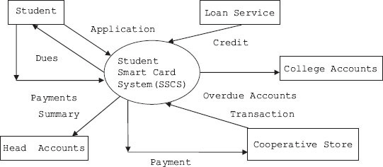
Figure 5.9 Context diagram for student smart card system
5.4.2 Context Diagram
Context diagrams depict the boundary between the system and the outside world, and highlights the people, organizations, and outside systems that interact with the system under development. The context diagram is presented in Figure 5.7.
5.4.3 Event List
- Student applies for a smart card
- SSCS informs student his dues
- Student pays his dues
- Student makes a transaction with coop stores
- Student is offered a loan
- Student has been given a credit
5.4.4 Data Flow Diagrams
Student requests for registration. The SSCS system checks status of tuition fees paid from accounts section and also obtains students’ records from students’ database and processes the request. If found eligible, the system issues authorization for registration process.
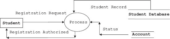
Figure 5.10a DFD for registration process – SSCS system
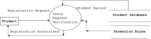
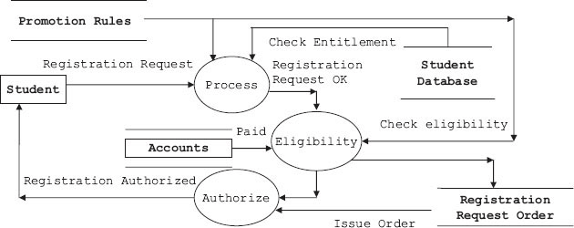
Figure 5.10c Issue request processing system
5.4.5 Data Dictionary
Data dictionary only maintains information to manage data but holds no actual data. Database management system cannot function without data dictionary. We can call it meta data about data but not actual data. In the DFD shown above, we have used terms like student database, promotion rules, account database, etc. But what exactly is the structure of data in these storage spaces. Data dictionary defines data structure in these storage spaces:
   Student Record = roll number + Name + course + Semester + No of Back lag papers weightage
   Promotion rule: if (backlog paper weightage < 25) eligible = 1 else eligible = 0
   Reg. Authorization Sheet: roll number + Name + Semester + courses registered
   Roll Number: digit + digit + digit + digit + digit (As many digits as there are in roll number)
   Student Smart Card: Card Number = Uniquely identifies a card
   Format = digit + digit + digit + digit + digit + Hyphen + alphabet
   Range = 50595 0000 0000 0000 to 50595 9999 9999 9999
5.4.6 Entity Relationship Diagrams
Entities in the SSCS for transactions and payments by a student are: payments, bills, transactions and accounts. Relationships are:
- Student pays for a transaction using smart card
- Accounts section hold smart card information
- Accounts generate bills
- Bills contain transactions
- Accounts receive payments
5.4.7 Process Specifications – SSCS
- For payments, entity process specifications are:
- Read account
- Read amount
- Add amount to account's credit
- Add amount to account's balance
- Update payment as applied
We leave writing specifications for balance entities for transactions, card, accounts, etc. as an exercise for the reader.
5.4.8 Structured Analysis and Design – Advantages and Disadvantages
Advantages
- It has clearly distinguishable phases, hence amenable to project management.
- DFDs, ERDs, etc., are easy to understand graphical tools.
- Widely used in industry and mature technique.
- Function/process oriented. It follows natural thinking process.
- Modular and hence flexible.
Disadvantages
- Only functional requirements are met. Ignores non-functional requirements.
- User–analyst interactions cannot be automated. It is manual and non-iterative.
- Communications with user after requirement analysis is non-existent.
- Hard to decide when to stop decomposing.
Where to use structure analysis and design
- SASD is best suited for very well-known and standard domains.
- Areas where SRS is specified.
- In transaction processing systems.
- When good amount of development time is available.
5.5 Object-oriented Software Analysis and Design (OOAD)
OOAD as it is popularly called is structural analysis and design and certain object-oriented features built over it. Accordingly, we start with user specifications and add the following object-oriented features:
- List of objects drawn out of grammatical parsing of narrative statement. Data content of nouns or entities from DFDs are of interest to us.
- List the system behaviour from verbs.
- Service provided by the object to other objects.
- Expand the objects and the relationships with other objects.
5.5.1 Different Models for Object Analysis
In OOAD methodology, interaction with user is very heavy. It does not end with drawl of specifications and user signs off the document. OOAD methodologies depend on various methodologies propounded by Rumbaugh, Grady Booch, Coad–Yourdon and Shlaer–Mellor. We will review these systems in the next section. The requirements keep changing during the development period of a complex project and there is a requirement to effect these changes and many a times this aspect causes design changes from step 1. OOAD works with the assumption that specifications will change and hence follows an iterative development pattern. Each iterative step either adds a new step or modifies the existing step.
5.5.1.1 The Rumbaugh Method
Rumbaugh is associated with the development of OOAD methodology that has a well-defined analysis as well as a design model. The analysis wing of the Rumbaugh model deals with object modelling technique (OMT). It further includes a model to study the dynamic behaviour of the system under development. The Rumbaugh model also includes functional modelling. Rumbaugh's model is similar to the SASD techniques discussed so far, with the additions for the object model, including definitions of classes along with their member data and functions and their interactions with other classes. Dynamic modelling includes state transition diagrams that show how an object changes from one state to another as an event occurs. Functional specifications are taken care by DFDs.
5.5.1.2 The Booch Method
Booch's methodology includes requirement analysis phase that is similar to the SASD practice. In addition, Booch's methodology includes domain analysis phase as part of the analysis phase. Booch's methodology enjoys strong design techniques and is divided into four parts:
- Part 1: Logical structure design where the class hierarchies are defined
- Part 2: Physical structure describing objects methods
- Part 3: Dynamic modelling showing state transitions and analysis of object transitions
- Part 4: Functional specifications
5.5.1.3 The Coad–Yourdon Method
Analysis phase is called SOSAS, meaning five steps in analysis and design phases:
- S stands for subject. It means DFDs.
- O for objects. Identify objects and class hierarchies.
- S for structure. It is divided into inheritance structures and composition structures. The classification is based on which of the two methods of extending the class, i.e. inheritance or composition is used in design.
- Attributes.
- Services offered by this class to others.
Design phase: It consists of four parts:
- Problem domain. Contains classes that belong to the problem domain.
- Human–computer interaction.
- Function management. Systemwide classes responsible for functions and management are identified.
- Data management: attributes of the system.
5.5.1.4 The Shlaer–Mellor Method
The model has three parts in system analysis and design:
- Information model comprises objects, member data, its relations with other objects.
- State model comprises different states of the objects and changes that can occur as objects do a transition.
- Process model takes care of functional specification.
In our book, we follow the best of all methodologies suggested above.
The first activity to be performed in OOAD is requirement gathering. A series of meetings with users gives us a narrative of the problem involved. Users based on the experience gained in operation of a manual system of shortcomings in an existing system would have prepared problem statements or using the tools available may have use cases. Object-oriented classes support the object-oriented principles of abstraction, encapsulation, polymorphism and reusability. Classes are specifications for objects. Derived from the use cases or problem statement or narrative, classes provide an abstraction of the requirements and provide the internal view of the application. The steps we would follow in OOAD are as follows.
5.5.2 Identifying Classes
Identifying classes can be challenging. Poorly chosen classes can complicate the applications logical structure, reduce reusability and hinder maintenance.
- Once narrative is available, we do a grammatical parsing to identify nouns, verbs, etc. Make an initial list of nouns. We call this list as candidate classes.
- Candidate Classes: Initial set of classes from which the actual set will emerge. Candidate classes can be identified by several methods. Two of the methods are shown below:
- Grammatical parsing of narrative or use cases or problem description: Identify the nouns and noun phrases, verbs and adjectives.
- Class responsibility collaboration (CRC) cards. These are a collection of cards, wherein class name, its responsibilities (functionality) and collaborations (service to other classes) are listed.
- Analyse the candidate classes. Look for collaborating classes. How does one class relate to another class? If it is collaborating, then retain the class else discard it.
- Follow the principle of selection of final classes suggested by Coad and Youdron to select a final list of classes. We call this set as design classes.
- Does the class have retained information?
- Is the service provided by the class needed by other classes?
- Does the class have multiple attributes?
- Does the class have common attributes that are useful to others?
- Does the class have common operations that are useful to others?
- Does the class come under essential category and is required by other classes?
5.5.3 Identifying Attributes
Attributes define the characteristics of the class. When looking for attributes in the design model, look for these types:
- Look for descriptive attributes.
- What characteristics distinguish this class from other classes?
- Names are used to uniquely identify the objects. What characteristics uniquely identify this object?
- How is a particular object linked to other objects?
5.5.4 Specifying Operations
For specifying the class operations, identify the operations each class performs. This list stems from the responsibility of the class. Operations specify the behaviour of the class. The operations can be classified as
- Modifier operations. These operations modify the attributes.
- Checks status of operations through checking a few attributes’ values.
- Transformation operation runs an algorithm or formula.
- Operation to check occurrence of an event.
Once operations and attributes are decided, we can finalize the definition of class. Let us use the college administration system for demonstration of OOAD principles. The design classes identified from the narrative are: professor, student, course, etc.
5.5.5 Work Out Associations
Associations are the key to identifying cohesive classes. Classes are associated with, or related to, other classes. Relations between classes occur when a class has some service to offer to other classes or uses services offered by other classes. A relationship is an association between classes.
How to identify the relationships?
- Start with a core class that interacts with many other classes.
- Ask questions like: Who is interested in this class? Why is this class required?
- Who uses services provided by this class?
5.5.5.1 Start with Main Associations
In our case, we will start with professor and student. Association, as we have learnt earlier, is a solid line that connects two classes.
Figure 5.12a Professor is associated with student
5.5.5.2 Many a Times Naming the Association Clarifies the Relationship
Figure 5.12b Naming the association
5.5.5.3 Highlight the Roles of the Classes in the Association
Giving a role is optional. But when given, it must a noun for a class. For example, we give a role of teacher to a professor and learner to a student.
Figure 5.12c Roles in an association
5.5.5.4 Introduce Multiplicity Factor
A role can have multiplicity relationship. Multiplicity indicators can be conditional or unconditional. For example:
Figure 5.12d A professor can teach 0 to many students
Figure 5.12e A student can teach 0 to 1 student
Figure 5.12f A professor can have 0 to many students. But a student must have at least one professor
5.5.5.5 Association Class
Association classes are required to be created, when there is a set of data that does not belong strictly to any one of the participating classes. For example, if there are two classes like student and course, then to which class do grade and attendance belong? There are several different grades gained by student and different attendance scoresone for each course. Where do we store this kind of data? Where to place the GRADE? If we place it in student, the student will get the same grade for all courses. On the other hand, if we place the grade in course file, then all students taking the same course will get the same grade.
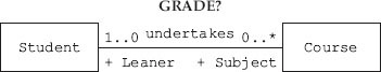
Figure 5.13a A student can undertake 0 to many courses
The solution is creating an Association class. An Association class will have its own attributes and methods, pointers and references to both of the participating classes.
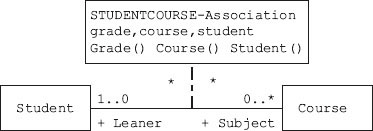
Figure 5.13b An association class
5.5.5.6 Composition
A class can contain other classes. For example, Student class can contain Date class. This can be viewed as whole–part relation. The life cycle of part is dependent on the life cycle of whole. It also means that when the whole is deleted, the part also gets deleted. To decide about composition, the questions that are to be asked are:
- Is this class part of some other class?
- Is this class destroyed when some other class gets destroyed?
5.5.5.7 Aggregation
Here, the part is not destroyed when the whole is destroyed. This is equivalent of a “has” type of relation. For example, a computer has a microprocessor. When the computer is destroyed, the microprocessor may not be destroyed. Another example of aggregation is: an automobile has an engine, wheels, etc. The critical question to be asked is: Is this class part of another class and is it independent of the other class?
5.5.5.8 Generalization/Specialization
The generalization and specialization stems from inheritance relationship. Base class can be considered as a generalized class whereas a class extended from the base class is a specialized derived class. This association is commonly referred to as inheritance because the derived classes inherit the functionality of their base classes to provide specialized behaviour. Inheritance provides the mechanism for new classes to be formed from the attributes and behaviour of existing classes. This is a “is” kind of relationship. The key question to be asked to identify inheritance relationships are: Is this class a specialization of a more general class?
5.5.5.9 Interface
An interface provides a common specification for behaviour, but, unlike an inherited class, an interface cannot be created or instantiated. An interface simply specifies common behaviour that other classes inherit. This means that interface has only method names and no implementations. Implementation is left to inherited classes from the interface which implement these methods differently. This means that unrelated classes can provide independent implementations. This is termed as run-time polymorphism.
5.6 OOAD: A Case Study
The first activity to be performed is requirement gathering. A series of meetings with users gives us a narrative of the problem involved. We are here to solve by designing an automated grievance redressal mechanism for a college. We would call this system as GRC System (GRCSYS). Once the narrative is available, we do a grammatical parsing to identify nouns, verbs, etc. We have shown nouns and verbs in the narrative below. Nouns, we have shown in bold and underlined while verbs are in italics and bold.
Grievance Redressal Committee (GRC) of a university, headed by Chairman Grievance Redressal Committee (CGRC) inquires into grievance of students regarding girl-related matters, ragging, academic matters, and campus infrastructure-related aspects, and hostel and mess. A Student can log on to GRC System (GRCSYS) web site available both on College Intranet and InternerWebsite (GRCSITE) and report the grievance, indicating grievance details (GRCDET) such as roll Number, class, course, type of grievance (TGRC), and date of occurrence (DOC) of grievance. They are allocated a token number (TNO) of the grievance. For operating web account, each student is provided with a password.
When a complaint is received on the web, CGRC calls for GRC. GRC in turn looks into the grievance and in consultation with concerned faculty and or Department organizes events such as organizing extra coaching or special training, taking action on defaulting students and other necessary actions.
Action initiated report (AIR) and action taken report (ATR) are initiated and informed to Student via web site. A suitable interface is provided for displaying on the web site to Students and Parents to get the reports of AIR and ATR, called AirReport and AtrReport with in a minimum time prescribed (TimePeriod).
Develop object-oriented analysis model for the above narration.
Parsing of narrative presented above, we can identify the following Candidate classes:
| Grievance Redressal Committee (GRC) | System (GRCSYS) |
| CollegeIntranet | GRCSITE |
| Chairman Grievance Redressal Committee (CGRC) | Student |
| Grievance | Class |
| Course | DOC |
| GRCDET | password. |
| TGRC | AIR |
| Token Number (TNO) | time period (PERIOD) |
| Faculty | Department |
| Event | AIR |
| ATR |
Once the list is made, analyse the candidate classes. Look for collaborating classes. How does one class relate to another class? If it is collaborating then retain the class else discard it. Coad and Yourdon in their study suggested the following criteria to convert candidate classes into design classes:
- Does the class have retained information?
- Is the service provided by the class needed by other classes?
- Does the class have multiple attributes?
- Does the class have common attributes that are useful to others?
- Does the class have common operations that are useful to others?
- Does the class come under essential category and is required by other classes?
Step 2: Let Us Apply the Above Criteria to Our Candidate Classes
Step 3: Make a List of Design Classes
| System (GRCSYS) | CollegeIntranet |
| GRCSITE | Student |
| Grievance | GRCDET |
| AIR | AIR |
| Event |
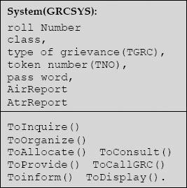
Let us consider System (GRCSYS) to work out further OOAD processes. We leave specifying operations and attributes as an exercise to readers.
Step 4: Specify Attributes
For specifying the class attributes
- Look for descriptive attributes.
- What characteristics distinguish this class from other classes?
- Names are used to uniquely identify the objects. What characteristics uniquely identify this object?
- How is a particular object linked to other objects?
roll Number, class, course, type of grievance (TGRC), date of occurrence (DOC) of grievance. token number (TNO), password, AirReport and AtrReport
From the above list identify the attributes that belong to System (GRCSYS)
roll Number, class, type of grievance (TGRC), token number (TNO), password, AirReport and AtrReport
Step 5: Specify Operations
For specifying the class operations, identify the operations each class performs. This list stems from the responsibility of the class. Operations specify the behaviour of the class. The operations can be classified as
- Modifier operations – These operations modify the attributes.
- Checks status of operations through checking a few attributes value.
- Transformation operation runs an algorithm or formula.
- Operation to check occurrence of an event.
| ToInquire() | ToLogOn() | Toreport() |
| ToAllocate() | ToOperate() | ToProvide() |
| ToCallGRC() | ToOrganize() | ToConsult() |
| ToInitiate() | ToInform() | ToDisplay() |
From the above list we can identify the operations of System (GRCSYS):
| ToInquire() | ToAllocate() |
| ToProvide() | ToCallGRC() |
| ToCallGRC() | ToOrganize() |
| ToConsult() | ToInitiate() |
| ToInform() | ToDisplay() |
Now we can complete the class diagram for System (GRCSYS) class
5.7 Design for Reuse
Designing software project using OOAD principles is a complex process and design OOAD project with reusability features is even more difficult. But because of the enhancement of productivity, we need to use reusability features. The reusability features concentrates on two major aspects:
- Reusability of code: This is a built-in language feature and uses extendibility features of object-oriented language features such as composition, aggregation, inheritance, interface, etc.
- Reusability of design: This aspect concentrates on building software domain architecture as a framework for reuse activities. It is much more than mere code reuse. It is a domain engineering practice.
The idea behind reusability plank is not to try to derive and design from the first principles. Rather use the tried and tested classes that have gone through refinements. These classes form a “design pattern.” So what is a design pattern? First of all, the problem should have occurred repeatedly and there should be a recognizable pattern, so that under similar situations, the design pattern could be made use of for elegant solutions. In other words, design pattern allows us to choose from design alternatives and make the system reusable. Design patterns have the following characteristics.
- Pattern Name: Identifies the design pattern for reuse. Pattern name describes a design problem, its solutions, its consequences a word or two.
- Problem: Describes the problem and when to apply a particular design pattern. For example, problem describes specific design problems of representing algorithm as object, etc. The problem may include conditions that must be met before we apply the design pattern.
- Solution: Elements of design, their relationships, responsibilities and collaborations. Solution cannot be an exact solution since design pattern is like a template which has to be fitted for a particular problem. The design pattern provides an abstract description of a design problem and arrangement of classes and objects to solve the problem.
- Consequences: There are consequences of applying a design pattern to a problem. Listing of these consequences help a designer to choose from the alternatives.
How can design pattern help a designer?
- To identify less obvious objects such as a process or an algorithm.
- To decide what should be an object – in other words, object granularity.
- To specify object interfaces.
- To specify object implementations.
Principles of Reusable Object-oriented Design
- Inheritance extends a class functionality and one can get a new class merely by extending an existing class.
- Due to polymorphic property, all derived classes share the same interface. The users of interface are governed only by interface and are generally unaware of implementation by derived class. This a great feature of reuse. We can program to an interface rather to an implementation.
- Inheritance by extending functionality can be seen as breaking encapsulation whereas composition has well-defined interfaces for the objects being composed and hence implementation is hidden because of interface. Hence composition is a better reusability feature than an inheritance.
- Generic programming using templates is a third method for reusability feature, in addition to inheritance and composition. Parameterized templates allow us to define a type without specifying all other types. The type can then be passed at run-time as an argument. For example, we can pass “integer” as a type to list parameterized type.
5.8 Comparison of SASD and OOAD Methodologies
- Step-by-step stagewise development and documentation.
- Both techniques use graphical design and graphical tools such as CASE and UML to analyse and model the requirements.
Differences
- SASD is process-oriented.
- OOAD is data-oriented.
- OOAD encapsulates Data and Process.
- Heavy reliance of OOAD on reusable components.
- In SASD, the user requirements are collected and specifications are drawn based on requirements, and users are then asked to sign off on the specifications.
- In OOAD, the requirements and specifications are matched repeatedly over the entire development period and users are involved at each stage.
5.9 Summary
- There are four phases in project management, namely: inception, elaboration, construction and delivery.
- Waterfall model of software development life cycle closely follows structural analysis and design methodology and is widely used in industry.
- Structured analysis and design (SASD) methodology is used to convert business model into specifications that can be used to develop computer-based programs.
- SASD technique attempts to solve the complex problem by dividing large, complex problems into smaller, more easily handled ones. The technique can be called the divide and conquer method. The approach adopted can also be called the top-down approach.
- SASD comprises data modelling and functional modelling. Data flow and control are depicted using DFDs.
- The main elements of SASD are: (1) statement of purpose, (2) context diagram, (3) event list, (4) DFDs, (5) data dictionary, (6) entity relation diagrams, etc.
- Context diagram of SASD is a set of inputs and outputs and a transformation system.
- The purpose of event list is to prepare a list of external events/activities to which system under design should respond.
- Data flow diagrams (DFDs), also called data flow graphs, are used in the analysis phase. A DFD views function as data flows through the system. DFD highlights the data transformation from input stage to output stage through various processes.
- A data dictionary or database dictionary is a file that defines the database. Data dictionary only maintains information to manage data but holds no actual data. We can call it meta data about data but not actual data.
- Entity relationship diagram (ERD) is a graphical representation of the data layout of a system at a high level of abstraction. It defines data elements and their inter-relationships in the system.
- Process specifications show process details, which are not shown in a DFD. Input, output and algorithm of a module in the DFD are included in process specifications.
- Functional Decomposition: In order to be effective, we need to specify constraints and operations so that original specifications and requirements are not compromised because of functional decomposition.
- Object-oriented classes support the object-oriented principles of abstraction, encapsulation, polymorphism and reusability. Classes are specifications for objects.
- Classes arederived from the use cases or problem statement or narrative; classes provide an abstraction of the requirements and provide an internal view of the application.
- The stages in OOAD are: (1) identifying classes, (2) identifying attributes, (3) specifying operations and (4) work out associations and relationships.
- A relationship is an association between classes. Relations between classes occur when a class has some service to offer to other classes or uses services offered by other classes.
- Association classes are required to be created, when there is a set of data that does not belong strictly to any one of the participating classes.
- In composition, a class can contain other classes. For example, Student class can contain Date class. This can be viewed as a whole–part relation. It also means that when the whole is deleted, the part also gets deleted.
- In aggregation, the part is not destroyed when the whole is destroyed. This is equivalent of a “has” type of relation.
- The generalization and specialization stems from inheritance relationship. Base class can be considered as a generalized class whereas a class extended from the base class is a specialized derived class.
- An interface provides a common specification for behaviour, but, unlike an inherited class, an interface cannot be created or instantiated. An interface simply specifies common behaviour that other classes inherit.
- Reusability revolves about reusability of code and reusability afforded through the use of design pattern.
- A design pattern is a pattern formed when a problem occurs repeatedly and there is a recognizable pattern, so that under similar situations, the design pattern could be made use of for elegant solutions. In other words, design pattern allows us to choose from design alternatives and make the system reusable.
- Inheritance, composition and parameterized templates are the tools provided by objectoriented languages to ensure reusability features.
Exercise Questions
Objective Questions
- Specifications are deliverables for
- feasibility study
- analysis phase
- design phase
- problem definition.
- Which of the following statements are NOT true in case of the waterfall model?
- Resources can be committed incrementally and not all at once.
- Stagewise documentation is available.
- It follows SASD design methodology.
- It is an incremental model.
- Which of the following statements are true?
- OOAD is process oriented
- SASD is process oriented
- OOAD encapsulates data and process
- SASD models requirements
- i
- i and ii
- i, ii and iii
- ii, iii and iv
- Which of the following statements are true with respect to SASD?
- Developed in the late 1970s by DeMarco, Yourdon and Constantine
- SASD is process oriented
- SASD models requirements
- SASD takes care of both functional and non-functional requirements
- i
- i and ii
- i, ii and iii
- ii, iii and iv
- Scope of the project is defined by
- Statement of purpose
- Context diagram
- Narrative
- Event list
- Which of the following is false with respect to context diagram?
- Context diagram defines the purpose of the project.
- Interaction of external elements with system under development.
- Shows inputs, outputs and transformation functions.
- Context diagram and data flow diagram are one and the same.
- i and iv
- i and iii
- i, ii and iii
- None
- Which of the following are true?
- DFDs are functional decomposition of the main process.
- DFDs are graphical representations of the decomposition process.
- DFDs describe the data required to meet functional specifications.
- DFDs depict data flow but do not show control flow.
- i
- i and ii
- i, ii and iv
- ii, iii and iv
- Which of the following are true?
- DFDs are useful in the analysis phase.
- DFDs are useful in the design phase.
- DFDs describe functions as data flows.
- DFDs describe data transformation.
- i
- i and ii
- i, ii and iv
- i, ii, iii and iv
- Which of the following are false regarding data dictionary?
- Data dictionary is a list of files and databases.
- Data dictionary holds actual data.
- Defining data dictionary is optional.
- Data dictionary describes data transformation.
- i
- i, ii and iii
- ii, iii and iv
- i, ii, iii and iv
- Which of the following statements are true with respect to ERDs?
- ERD is a graphical representation.
- ERD is a data layout and their inter-relations between data elements.
- ERD symbol.
 represents relationship.
  symbol represents data element.
- i
- i, ii and iii
- ii, iii and iv
- i, ii, iii and iv
- Which of the following statements are true regarding OOAD?
- Classes are specifications for objects.
- CRC cards can be used to decide the classes in OOAD.
- A relationship is an association between classes.
- Association can both not have multiplicity of roles
- i
- i, ii and iii
- ii, iii and iv
- i, ii, iii and iv
- Which of the following statements are true with respect to OO language?
- Association class is created when there is data that does not belong strictly to a single class.
- Composition depicts a whole–part relationship.
- A composition depicts a “has” type of relationship.
- In aggregation, part is destroyed when the whole is destroyed.
- i and ii
- i, ii and iii
- iii and iv
- i, ii, iii and iv
- Which of the statements are false with respect to inheritance relationship?
- Inheritance depicts a “has” type of relationship.
- Inheritance depicts an “is” type of relationship.
- Generalization refers to derived class in inheritance relationship.
- Specialization refers to derived class in inheritance relationship.
- i and iv
- i, ii and iii
- ii, iii and iv
- i, ii, iii and iv
- Which of the following statements are true with respect to reusability in OOAD?
- Reusability uses design patterns.
- Reusability means both reusability of code and reusability of design.
- Inheritance is better for reusability feature than composition.
- Interface is a feature that helps greatly in achieving reusability.
- i and iv
- i, ii and iii
- ii, iii and iv
- i, ii, iii and iv
- Which of the following features aid reusability features of OO language?
- Parameterized templates
- Composition
- Inheritance
- Interface
- i, ii and iii
- i, ii and iv
- i, ii, iii and iv
- ii, iii and iv
Short-answer Questions
- What are the stages in project management?
- What are the main elements of SASD?
- Explain the purpose of context diagram in SASD. Explain the notations used in context diagram?
- What is a data dictionary and why is it required?
- What is statement of purpose? Is it a clear and concise statement highlighting the purpose of the system?
- What are the elements of SASD?
- What are the elements of data dictionary?
- What is ERD?
- What are the symbols used in ERDs?
- Why are specifying process and constraints important in SASD?
- Explain Composition, Aggregation and Association class.
- Explain the terms generalization, specialization, interface and design pattern.
Long-answer Questions
- Explain the waterfall model of the software development life cycle. What are its advantages and disadvantages?
- Explain functional decomposition in SASD. What is the role of DFD in functional decomposition and analysis?
- Explain the role and usefulness of ERDs in SASD.
- What are the advantages and disadvantages of SASD?
- When do you use SASD?
- When do you use OOAD?
- Distinguish between SASD and OOAD techniques.
- What is an association in OOAD? Explain with examples.
- Distinguish between composition and aggregation.
- Distinguish between inheritance and interface. What are generalization and specialization? How are they related to inheritance?
- What are design patterns? Explain their contribution to reusability features of a modern object-oriented language like Java or C++.
- What are the advantages and disadvantages of using SASD methodology? Explain the areas SASD methodology is efficient.
Assignment Questions
- Write a narrative for students admission process in a professional college and do grammatical parsing to identify classes and their associations.
- Write a narrative for college academic administration of a professional college. Include areas like departments offering courses, students registering for a course, professor handling courses, students’ performance in the form of grades, etc. Draw class diagram, depicting associations and relationships.
- Write a narrative for book ordering system of a library. Identify the objects using grammatical parsing techniques.
- Carry out object-oriented analysis and design for online purchase of items from an Internet-based E-Shop.
Solutions to Objective Questions
- b
- d
- d
- c
- b
- a
- c
- d
- c
- d
- b
- c
- a
- b
- c