
Chapter 7
Laser Fluorosensors
Abstract
Laser fluorosensors have shown significant potential for the remote sensing of petroleum oils because they can discriminate between oiled and unoiled situations, and detect oil in a variety of marine and terrestrial environments including on water, snow, ice, beaches, and with debris and weeds. Tests on shorelines show that this technique is very successful. Laser fluorosensors have been developed over the past four decades for the purpose of airborne surveillance and monitoring of oil spills, and the exploration of marine petroleum resources. Laser fluorosensors have gone through a progression from experimental to operational sensor that provides both a positive indication of oil and a classification of oil type. This chapter provides a brief introduction into the principles of operation of laser fluorosensors, oil detection and classification, brief details of existing operational units and aircraft requirements, and closes with some cost estimates.
Keywords
Laser fluorosensors; Oil spill remote sensing
7.1. Principles of Operation
7.1.1. Active Versus Passive Sensors
Passive sensors are those which measure naturally available energy such as that produced by the sun [1]. Passive sensors can only be used when the naturally occurring energy is available, that is, during periods of daylight when the sun is illuminating the earth. Passive sensors cannot therefore be used during night. However, some naturally emitted energy such as thermal infrared energy can be detected during the day or night, provided there is enough energy to be detected. Active sensors, on the other hand, provide their own energy or source of excitation for illumination. The sensor illuminates or excites the target to be investigated. The energy or radiation reflected from that target is then detected and measured by the active sensor. The main advantage of active sensors is the ability to obtain measurements anytime of day/night. Furthermore, active sensors can be used at wavelengths, such as the microwave region, that are not provided by the sun. It should be noted that active remote sensors require the generation of a large amount of energy in order to adequately illuminate the targets. Examples of active remote sensors include synthetic aperture radars and laser fluorosensors.
7.1.2. Sensor Features
Laser fluorosensors are the only sensors that detect a primary characteristic of oil, namely, the oil fluorescence spectral signature. Other generic sensors rely on secondary characteristics of oil, such as the reflection of light of various wavelengths, scattering of microwaves, and emission of infrared energy.
Laser fluorosensors are active sensors that take advantage of the fact that certain compounds in petroleum oils absorb ultraviolet light and become electronically excited. This excitation is rapidly removed through the process of fluorescence emission, primarily in the visible region of the spectrum. Since very few other compounds show this tendency, fluorescence is a strong indication of the presence of oil. Natural fluorescing substances, such as chlorophyll, fluoresce at sufficiently different wavelengths than oil to avoid confusion. As different types of oil yield slightly different fluorescent intensities and spectral signatures, it is possible to differentiate between classes of oil under ideal conditions [2–10].
7.1.2.1. Excitation Source and Wavelength Selection
Most laser fluorosensors used for oil spill detection employ a laser excitation source operating in the ultraviolet region of 300–355 nm [4]. The fluorescence response of crude oil when excited with an ultraviolet laser ranges from 400 to 650 nm with peak centers in the 480 nm region. A typical laser fluorosensor system with excimer laser and scanner is shown in Fig. 7.1. These excitation wavelengths are a compromise in that they excite all three classes of oil (light, medium, and heavy) with reasonable efficiency (shorter wavelength lasers would excite lighter oils efficiently but would be rather poor at exciting crude and heavy refined oils). There are several reasonably priced, commercially available, ultraviolet lasers in the 300–355 nm region including the XeCl excimer laser (308 nm), nitrogen laser (337 nm), XeF excimer laser at 351 nm, and frequency tripled Nd:YAG at 355 nm. With excitation in this wavelength region, there exists a broad organic matter fluorescent return, centered at 420 nm. This is referred to as Gelbstoff or yellow matter, which must be accounted for. While Gelbstoff disappears if the oil thickness is greater than 10–20 μm (i.e., where the oil is optically thick), it can be an interfering signal when attempting to detect thin films of light oils on water. Chlorophyll yields a sharp peak at 685 nm.
Another phenomenon, known as Raman scattering, involves energy transfer between the incident light and the water molecules. When the incident ultraviolet light interacts with the water molecules, Raman scattering occurs. The water molecules absorb some of the energy as rotational–vibrational energy and emit light at wavelengths which are the sum or difference between the incident radiation and the rotational–vibrational energy of the molecule. The Raman signal for water occurs at 344 nm when the incident wavelength is 308 nm (XeCl laser). The water Raman signal is useful for maintaining wavelength calibration of the fluorosensor in operation, but has also been used in a limited way to estimate oil thickness, because the strong absorption by oil on the surface will suppress the water Raman signal in proportion to thickness [11], where transmittance = EXP (−thickness × absorption coefficient). The point at which the Raman signal is entirely suppressed depends on the type of oil, since each oil has a different absorption coefficient. The Raman signal suppression has led to estimates of sensor detection limits of about 0.05–0.1 μm [12]. Details of the use of Raman scattering to measure oil slick thickness can be found in the early work of Hoge and Swift [13] and the studies by Patsayeva et al. [14].

7.1.2.2. Detection System
The detection systems in most laser fluorosensor systems usually involve the collection of laser-induced fluorescence by a telescope, the focusing of the fluorescence onto the entrance slit of a grating spectrometer, and then onto intensified diode arrays. The fluorescence spectrum is then recorded at a number of selected wavelengths or over a wide spectral range covering the ultraviolet through the visible.
7.1.2.3. Range-Gating
The majority of modern laser fluorosensors are equipped with range-gated detection systems. Range-gating is simply the turning on of the detection system at precisely the time at which the laser-induced fluorescence is expected to return to the laser fluorosensor. This is accomplished by turning the detection system on and off at a precise time based on the known altitude. To accomplish this, the timing of the laser pulse is monitored prior to exiting the aircraft and the elastic backscatter from the surface is then monitored to determine the precise aircraft altitude, which is then used to control the range-gating electronics. This allows the detector to observe only the fluorescence induced by the excitation laser and neglect the majority of the background solar radiation.
7.1.2.4. Field-of-View—Fixed Versus Scanning Systems
As noted earlier, active sensors need to deliver sufficient energy onto the target, the surface of the earth containing oil contamination, to excite sufficient fluorescence to allow for the detection and classification of the oil. With most airborne laser fluorosensor systems, this means illuminating a field-of-view (FOV) of about 1 × 3 mrad, giving a footprint on the surface of about 0.1 m × 0.3 m at 100 m altitude. This does not allow for a large amount of the surface to be interrogated by each laser pulse. With higher-powered ultraviolet lasers, one can fly at higher altitudes and enlarge the footprint of the sensor. The repetition rate of the laser and the ground speed of the aircraft are also major factors in the sampling of the surface where the oil contamination is being examined. At ground speeds of 100–140 knots (nautical miles per hour) at a laser repetition rate of 100 Hz, a fluorescence spectrum is collected approximately every 60 cm long the flight path (at 100 m altitude). Some laser fluorosensors only “look” directly below the aircraft and collect fluorescence spectra in a straight line; this is referred to as a “fixed” FOV system. As spilled oil often piles up in narrow bands at the high tide line, detection of this oil with a fixed FOV system is not optimal. This means that the oil might not be detected because the sensor is striking the surface of the earth on either side of the high tide line. To compensate for this tendency of the oil to accumulate in a narrow band, it is preferable to change the laser FOV by employing a scanner. The scanner can either be moved in a conical (circular) fashion or back and forth across the surface to increase the likelihood of striking the oil contamination. There are conical scanning laser fluorosensor systems developed in Germany [15] and Canada [16]. An example of a conical scanner is shown in Fig. 7.2.
7.1.3. Advantages/Disadvantages
Laser fluorosensors are capable of detecting oil and related petroleum products in complex marine, coastal, and terrestrial environments. These sensors are extremely sensitive and can discriminate between oiled and unoiled naturally occurring substances, such as kelp and seaweed. It is under these circumstances that the laser fluorosensor can aid in the direction of oil spill countermeasures by discriminating between contaminated and clean areas in the marine and terrestrial environment.

Laser fluorosensors are the only sensors that detect a primary characteristic of oil, namely the characteristic oil fluorescence spectral signature. Other, generic sensors rely on secondary characteristics of oil such as the reflection of light of various wavelengths, scattering of microwaves, and emission of infrared energy.
In the past, laser fluorosensors were very large, heavy, and power-hungry systems. These characteristics necessitate the use of large multiengined aircraft to house the systems. These conditions are no longer true because of the development of much smaller diode-pumped solid-state lasers in the ultraviolet region of the electromagnetic spectrum.
7.2. Oil Classification
7.2.1. Real-Time Analysis
One of the benefits of modern laser fluorosensors is the ability to detect and classify oil contamination in real time. This availability of real-time oil contamination is essential for rapid oil spill response and environmental damage mitigation. An analysis of oil spill detection algorithms for laser fluorosensors was undertaken by Jha et al. [17].
In earlier fluorosensors such as the laser environmental airborne fluorosensor (LEAF) system, Pearson correlation coefficients were calculated to determine the presence of oil contamination and to broadly classify the petroleum products [18]. Standard reference fluorescence spectra for light refined, crude, and heavy refined classes of oil, along with a standard water reference spectrum, were stored in the LEAF data analysis computer. Correlation coefficients were calculated for the live spectrum versus the three broad classes of petroleum products and water at the rate of 100 Hz. When the value of the correlation coefficient versus a class of petroleum product was above a certain level and greater than the correlation with the water spectrum, the live spectrum was identified as being of that class of petroleum.
With modern computer technology it is now possible to analyze a large amount of laser fluorosensor data in real time. For example, with the scanning laser environmental airborne fluorsensor (SLEAF) it is possible to analyze fluorescence data at a rate of nearly 400 Hz and display oil detections along with the flight path of the aircraft on a geo-referenced map output [8,19]. With the SLEAF system, fluorescence spectra are analyzed in real time to determine the presence or lack of oil in the sensor FOV. Principal component analysis [20] is used to classify the oil class as light, medium, or heavy and estimate the extent of oil coverage in the FOV as clean, light, moderate, or heavy.
7.2.2. Sensor Outputs
As noted earlier, a high volume of fluorescence spectral data can be analyzed in real time. In most laser fluorosensor systems the fluorescence data is geo-referenced (i.e., the location of the oil contamination is well known) and the data can be presented in either spectral or map display outputs. While displays of spectral data are important for the sensor operator to verify the proper operation of the sensor, they are of little use to the spill responder. What is essential for the spill responder is the knowledge of the location of oil contamination so that spill response equipment can be rapidly deployed to the spill scene and cleanup operations can be undertaken. The positive identification of oil contamination afforded through the use of laser fluorosensors is one of their main advantages.
7.2.2.1. Spectral Data
The display of spectral data is essential for the effective operation of modern laser fluorosensors. Laser fluorosensor display monitors often include a representation of sensor parameters, such as laser pulse energy, operating altitude, laser backscatter energy, reference spectra, and live or real-time fluorescence spectra. The observation of each of these parameters is extremely useful to the sensor operator. In particular, real-time spectra are useful to provide an indication of the interaction of the laser beam with the surface. By observing the live spectrum, the operator has an indication of the water clarity through observation of the water Raman scattering spectrum. A trained sensor operator can easily recognize the presence of oil contamination via the characteristic spectrum of light refined, crude, or heavy refined petroleum products. Fig. 7.3 shows typical laser-induced fluorescence spectra of a crude oil. The lack of a proper spectral signature can indicate a problem with the fluorosensor system such as low laser power, low laser backscatter signal, incorrect range-gate timing, or laser misalignment. It is impossible to display all of the spectral data collected with a high sampling rate laser fluorosensor system, a subsample of the spectral data is all that is needed for an experienced operator to monitor system operations.

7.2.2.2. Map Display
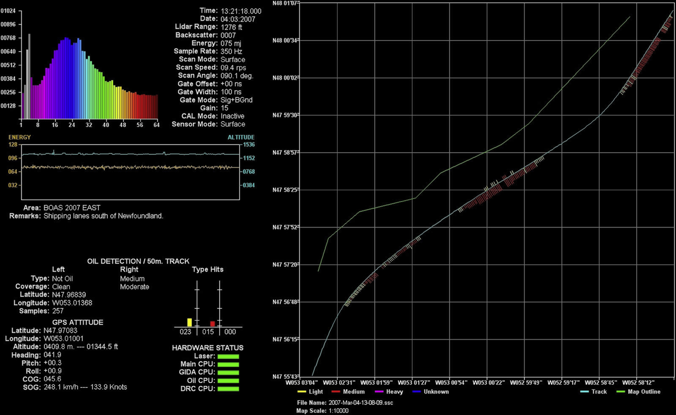
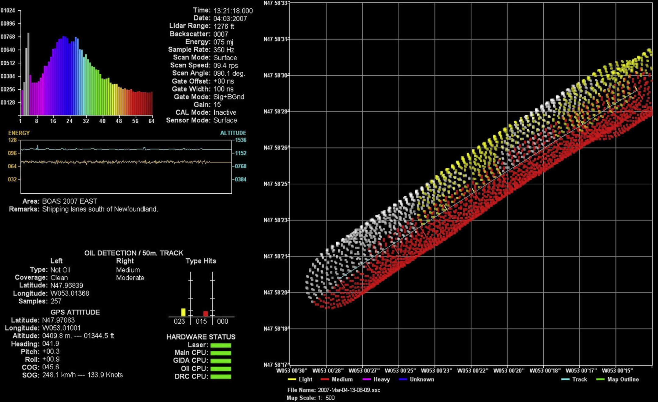
An accurate map display of oil contamination location(s) is essential for the rapid mitigation of the environmental effects of spilled oil. Displays of oil contamination superimposed over aircraft flight lines are useful for spill responders who participate in oil spill remote sensing over flights. Fig. 7.4 shows the operator's display from Environment Canada's SLEAF system. Fig. 7.5 shows the operator's display with areas of oil contamination illustrated as colored bars perpendicular to the flight path. Similar information is presented in Fig. 7.6 which overlays the scanner pattern on the flight path along with the oil contamination information (different colors for clean, light, medium, or heavy oil classifications). Spill response organizations and personnel are not interested in sensor parameters or spectral data. However, geo-referenced maps showing oil locations are necessary. These maps, or at least the geo-referenced oil contamination locations, should be in a format that can be transmitted electronically and compatible with commonly used geographical information systems. These maps will help in the rapid and efficient deployment of spill response resources and equipment to the location(s) where oil contamination is the heaviest and the cleanup of contamination is most needed.

7.3. Existing Operational Units
7.3.1. Airborne
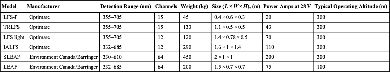
There are a number of operational airborne laser fluorosensor units operating around the globe. Some of these are research and development units which have progressed to become operational spill response sensors such as the SLEAF system [21]. Table 7.1 shows some operating parameters of present and past fluorosensors. Other laser fluorosensors have been combined with other sensors in commercially available sensor packages, while others are stand-alone systems or remain as research instruments. There are a number of recent reviews of airborne laser fluorosensor systems in the literature including those by Samberg [10], as well as Brown and Fingas [18,22], and Brown [23].
There are a number of commercially available airborne laser fluorosensors in the marketplace and a few examples are provided here. The first is the fluorescent LIDAR spectrometer (FLS-AU) developed by Laser Diagnostics Instruments International Incorporated. The FLS series of LIDARs are designed for pollution monitoring of terrestrial, river, lake and ocean targets, oil and gas pipeline leak detection, and oil exploration [23]. The second example is the laser fluorosensor system developed by Optimare Sensorsysteme AG as part of the MEDUSA system [24]. MEDUSA is a flexible real-time data acquisition and processing system, which combines a number of sensor technologies for the detection, mapping, quantification, and classification of marine pollution. MEDUSA incorporates a number of unique sensor systems, e.g., laser fluorosensors, infrared/ultraviolet line scanners, microwave radiometers, radar systems, camera systems, as well as the corresponding processing software. The final example is the S&T MSS 6000 Maritime Surveillance System which can be tailored to integrate with a number of sensors including a selection of side-looking airborne radar, infrared/ultraviolet (IR/UV) cameras, microwave radiometers, forward-looking infrared (FLIR), and laser fluorosensors [25].
Table 7.1
Some Fluorsensors in Production, Past and Present
| Model | Manufacturer | Status | Scanning | Time Resolved | Activation Laser | Wavelength (nm) | Detection Range (nm) |
| LFS-P | Optimare | Current | No | Yes | Tri-YAG | 355 | 355–705 |
| TRLFS | Optimare | Operational | No | Yes | Tri-YAG | 355 | 355–705 |
| LFS light | Optimare | Operational | No | Yes | Tri-YAG | 355 | 355–705 |
| IALFS | Optimare | Operational | Yes | Yes | Excimer | 308 | 332–685 |
| SLEAF | Environment Canada/Barringer | Retired | Yes | Yes | Excimer | 308 | 330–610 |
| LEAF | Environment Canada/Barringer | Retired | No | Yes | Excimer | 308 | 332–685 |

| Model | Manufacturer | Detection Range (nm) | Channels | Weight (kg) | Size (L × W × H), (m) | Power Amps at 28 V | Typical Operating Altitude (m) |
| LFS-P | Optimare | 355–705 | 15 | 45 | 0.4 × 0.6 × 0.3 | 20 | 300 |
| TRLFS | Optimare | 355–705 | 15 | 133 | 1.1 × 0.5 × 0.5 | 43 | 300 |
| LFS light | Optimare | 355–705 | 12 | 120 | 1.4 × 0.78 × 0.5 | 70 | 300 |
| IALFS | Optimare | 332–685 | 12 | 290 | 1.6 × 1 × 1.4 | 110 | 300 |
| SLEAF | Environment Canada/Barringer | 330–610 | 64 | 450 | 2 × 1 × 1 | 200 | 300 |
| LEAF | Environment Canada/Barringer | 332–685 | 64 | 200 | 1.5 × 0.7 × 0.7 | 75 | 100 |
7.3.2. Shipborne
There has been a small number of shipborne laser fluorosensors developed. Most shipborne laser fluorosensors are research and development technologies, although there have been recent commercial developments. Two examples of shipborne laser fluorosensors are the FLIDAR (Fluorescence LIDAR) developed by the research group at the Istituto di Ricerca sulle Onde Elettromagnetiche “Nello Carrarra” IROE-CNR [26] and the compact LIDAR system developed by the Japanese Ship Research Institute [27]. The FLIDAR system incorporates a XeCl excimer laser, a 12 spectral channel detection system, and a conical scanner to direct the ultraviolet laser beam onto the surface of the ocean alongside the marine vessel onto which the system is mounted. The compact system at the Japanese Ship Research Institute is frequency tripled Nd:YAG laser coupled to an intensified CCD camera and uses a series of optical band pass filters. One commercially available shipborne laser fluorosensor system is the FLS-S (Fluorescent LIDAR System–Shipborne) developed by Laser Diagnostics Instruments International Incorporated. The FLS-S is designed to detect, measure, and map natural Dissolved Organic Matter, oil pollution, photosynthetic algae, and other contaminants in water [23].
7.4. Aircraft Requirements
The combination of large size, heavy weight, and demanding power requirements for the ultraviolet lasers detailed below necessitate the use of midsized fixed wing propeller or turboprop aircraft for laser fluorosensor system installation. Typical aircraft housing laser fluorosensors have included the Dornier 228-212, Douglas DC-3, (see Fig. 7.7), CASA C-295, P-3B, and Beech B-99 [18].


7.4.1. Power
The high powered excimer lasers often employed in airborne laser fluorosensors for oil spill detection require a significant amount of power. This power is typically supplied in the form of 3-phase 208 VAC at 400 Hz for the excimer laser. Additional power is required for systems such as the laser scanner head in the form of 28 VDC and for sensor controller electronics at 220 VAC, 60 Hz. These power requirements necessitate the use of heavy duty aircraft power generators and a number of power invertors to supply the energy in the proper voltage, phase, and frequency.
7.4.2. Weight
Most laser fluorosensors for oil spill detection employ an ultraviolet excitation laser. In order to deliver enough laser pulse energy and a sufficient repetition rate for use in a fixed wing aircraft, an excimer laser is usually required. Laser fluorosensor systems that employ excimer lasers such as the XeCl laser operating at 308 nm, capable of producing 150 mJ/pulse at a repetition rate of 400 Hz (such as that used in the SLEAF system shown in Fig. 7.8) [21] are large and heavy, weighing over 450 kg. Smaller systems are possible with the use of frequency tripled Nd:YAG lasers operating at 355 nm, however, in the past, these lasers were not able to produce the high laser pulse energies and repetition rates to fly at higher altitudes with sufficient areal coverage. Newer units have higher repetition rates and are able to replace XeCl lasers in many applications with much less weight. A light-weight unit is shown in Fig. 7.9.

7.4.3. Operational Altitude
Operational altitudes for laser fluorosensors are entirely dependent on the output energy of the excitation laser and FOV of the system optics. Typical operating altitudes for lasers operating in the ultraviolet would be approximately 100 m for a system with 10 mJ/pulse of laser power, up to approximately 600 m for a laser output power of 150 mJ/pulse. The operational altitude will also determine the swath width achieved with a conical scanner, for details refer to Brown and Fingas [18]. Newer, high-power units are able to operate at higher altitudes than the older units.
7.5. Cost Estimates
The cost of a laser fluorosensor system is significant, partially due to the low production volume of these unique sensors. Cost estimates for three laser fluorosensor systems have been reported to be ranging from 150,000 to 500,000 USD by Tebeau et al. [28].
7.6. Conclusion
Laser fluorosensors capable of detecting oil and related petroleum products in complex marine, coastal, and terrestrial environments have been developed at a number of locations around the world. These sensors are extremely sensitive and can discriminate between oiled and unoiled, naturally occurring substances such as kelp and seaweed. It is under these circumstances that the laser fluorosensor can aid in the direction of oil spill countermeasures by discriminating between contaminated and clean areas in marine and terrestrial environments.
Laser fluorosensors are the only sensors that detect a primary characteristic of oil, namely the characteristic oil fluorescence spectral signature. Other, generic sensors rely on secondary characteristics of oil such as the reflection of light of various wavelengths, scattering of microwaves, and emission of infrared energy.
Advances in the fields of lasers, solid-state electronics, and computer operating hardware/software continue to fuel the development of advanced laser fluorosensors. While many of the current systems are large and require dedicated aircraft, the unique data sets available from these laser fluorosensors will ensure their continued development for years to come. Wide acceptance of laser fluorosensors as viable spill response tools has now been achieved because the size of the systems is reduced to a point where they can be flown routinely on small twin-engine aircraft. This reduction in size has come about because high-power, high-repetition rate, diode-pumped solid-state lasers are available.
..................Content has been hidden....................
You can't read the all page of ebook, please click here login for view all page.