
CHAPTER
5
Oracle Data Integrator
In the last chapter, we talked about Oracle GoldenGate and how it can be used in the data integration process. Oracle GoldenGate is a great tool for migrating, transforming, and replicating data to another platform; however, Oracle GoldenGate cannot do a lot of the heavy lifting needed to integrate data on a larger scale. For this reason, Oracle GoldenGate is a complementary tool to be used with Oracle Data Integrator.
Oracle Data Integrator is part of the Fusion Middleware products that Oracle provides for integrating data. This is Oracle’s tool for data integration regardless of structure, so data can be integrated into any data model. Oracle Data Integrator can be downloaded from the Oracle Technology Network (http://otn.oracle.com) and installed using Java JDK 1.6_x. Because Oracle Data Integrator is written in Java and downloaded as a compressed jar file, it can be ported to any platform.
In the data integration landscape, Oracle has placed Oracle Data Integrator at a critical point within the business world. Oracle Data Integrator is the best choice for any organization to use to develop, configure, and orchestrate the transformation of data. With its ability to work with Oracle GoldenGate, to cleanse and sort data, and to interact with Big Data, Oracle Data Integrator is primed for any use-case an organization can place on it.
The organization of the business data with transformation and integrations is important for maintaining business rules and applying consistent processes. The automation and tracking of the integration rules require proper tools in order to harness the business knowledge for applying to the data.
Although this chapter will not cover all the excellent functionalities that Oracle Data Integration provides, it will provide you with a starting place for utilizing Oracle Data Integrator. In this chapter, we will take a look at how to install Oracle Data Integrator, configure a repository to be used with your data models, and how to load files into the database. Let’s start by looking at how to install the Oracle Data Integrator.
Architecture
Before we take a look at how to install Oracle Data Integrator, let’s take a moment and talk about the architecture of the product. There are four core architectural concepts to understand. The architecture consists of the following components:
![]() Repositories
Repositories
![]() Users
Users
![]() Oracle Data Integrator Console
Oracle Data Integrator Console
Repositories
Repositories are the central component in the Oracle Data Integrator architecture. They store the configuration information about the IT infrastructure, metadata for all the applications, projects, scenarios, and the associated execution logs. The architecture of the repositories is designed to allow for several environments to exchange metadata and scenarios between different stages (for example, Development, Test, Quality Testing, and Production). Along with the sharing of metadata, a repository also acts as a change control system where objects can be archived and assigned different version numbers.

NOTE
ODI repository can be installed in an OLTP relational database.
The normal setup of Oracle Data Integrator consists of a single master repository and several work repositories. Objects that are configured by users are stored in one of these repository types.
Work Repository
A work repository contains the actual developed objects. You can have several work repositories that coexist in the same ODI architecture. This is beneficial because the work repositories store information for the following items:
![]() Models Schema definitions, datastore structures and metadata, field and attribute definitions, data quality constraints, cross-references, and data lineage
Models Schema definitions, datastore structures and metadata, field and attribute definitions, data quality constraints, cross-references, and data lineage
![]() Projects Business rules, packages, procedures, folders, knowledge modules, and variables
Projects Business rules, packages, procedures, folders, knowledge modules, and variables
![]() Scenario execution Execution of scenarios, scheduling information, and associated logs
Scenario execution Execution of scenarios, scheduling information, and associated logs
If a work repository contains only execution information, then it is referred to as an execution repository.
Master Repository
The master repository is the primary repository that stores the information used to interact with the Oracle Data Integration environment. The master repository stores the following information:
![]() Security Information related to users, profiles, and rights for the ODI platform
Security Information related to users, profiles, and rights for the ODI platform
![]() Topology Information related to technologies, server definitions, schemas, contexts, and languages
Topology Information related to technologies, server definitions, schemas, contexts, and languages
![]() Versioned Information related to what the object version is and what has been archived
Versioned Information related to what the object version is and what has been archived
Don’t get confused by the different types of repositories. It is much easier to remember that at the very basic configuration level, you will need a single master repository and a single work repository. The master and work repositories provide the business requirements for the data integration and allow for updates as requirements or data needs change.
Users
Four types of users will interact with Oracle Data Integrator: administrators, developers, operators, and business users. Each type of user will use the Oracle Data Integrator Console for different purposes. Administrators, developers, and operators will use ODI to administer the infrastructure, reverse-engineer the metadata, develop projects, and schedule, operate, and monitor the execution of jobs. The business users, along with others, typically only need read-only access to the repository. This way, they can view the repository, perform topology configurations, and view production operations. Business users can validate the integration with the read-only access and then work with developers and administrators to adjust and make sure the business rules apply. Even though the users are using the tool for different functions, they have to work together to validate, maintain, and update the data integrations.
Run-Time Agents
The run-time agents help with interaction within the Oracle Data Integrator environment. These agents come in three different types, each of which has a role within the Oracle Data Integrator configuration:
![]() Standalone agent
Standalone agent
![]() Standalone co-located agent
Standalone co-located agent
![]() Java EE agent
Java EE agent
Standalone Agent
A standalone agent runs in a separate Java Virtual Machine (JVM) process. It is used to access the work repository and the source and target data servers via a JDBC connection. A standalone agent can be installed on any server that has a Java Virtual Machine. The benefit to using a standalone agent is when you want to use a resource that is local to one of your data servers without installing a Java EE application server on that machine.
Standalone Co-located Agent
Just like the standalone agent, this version of the agent runs in a separate Java Virtual Machine (JVM) process, but is associated with a WebLogic server domain and controlled at the WebLogic administration server. This version of the standalone agent can be installed anywhere a JVM is installed, but it needs to connect to a WebLogic administration server to run. Using this standalone version is suited for when you want a centralized management of all applications in an enterprise application server.
Java EE Agent
The Java EE agent is deployed as a web application in a Java EE–compliant application server, such as Oracle WebLogic Server. This version of the agent benefits from the application server—for example, using the JDBC data sources or taking advantage of the cluster within the application server. This version of the agent is recommended when you want to have a centralized management of deployments and applications within the enterprise or if high availability is required.
Oracle Data Integrator Console
The Oracle Data Integrator Console is the primary way that users interact with Oracle Data Integrator. The Console is the point where business users (as well as developers, administrators and operators) can have access to the repository, work with the topology configuration, and monitor production operations through a user interface. The Console also allows the administrator to manage and monitor the different agent types.
NOTE
To make monitoring easier, a plug-in is available that allows interaction within Oracle Enterprise Manager 12c.
Now that you have a basic understanding of the different components in the Oracle Data Integrator architecture, let’s take a look at how you can install Oracle Data Integrator.
Installation
After downloading the .zip file for Oracle Data Integrator, unzip the .jar file to a temporary location. After the .jar file is uncompressed it can be installed using Java 1.7_x or greater. To aid in the installation of Oracle Data Integrator, make sure a current version of Java is available on the system and can be accessed by the user installing Oracle Data Integrator.
NOTE
Set $JAVA_HOME to point to the current version of the JDK being used to install Oracle Data Integrator.
Deploying the Binaries
With the .jar file extracted and $JAVA_HOME pointing to the correct Java Development Kit (JDK), you can now start the installation of Oracle Data Integrator. To begin the installation, issue the following command and press ENTER:
![]()
This will start the Oracle Universal Installer for Oracle Data Integrator.
After the installation has begun, the OUI starts, as shown in Figure 5-1, and asks you to provide the location for the Oracle Inventory and a user group that should have access to this inventory location.
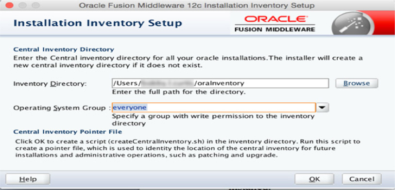
FIGURE 5-1. ODI Inventory installation
NOTE
In some installations, the screen shown in Figure 5-1 might not appear.
After you provide a location for the Oracle Inventory and a system group to use, the installation will begin. The traditional splash screen, shown in Figure 5-2, will appear and load the rest of the Oracle Universal Installer.

FIGURE 5-2. Oracle Universal Installer (OUI)
The Oracle Universal Installer will walk through the needed inputs to install Oracle Data Integrator. The welcome screen, shown in Figure 5-3, provides the relative information to begin the installation and lists what is needed. Down the left side of the Installer are the steps that the OUI will perform. Clicking Next causes the wizard to move to the next step.

FIGURE 5-3. ODI Installer Welcome screen
In the second step of the installation, the wizard asks for a location to place the Oracle Home, as entered in Figure 5-4. This location can be anywhere to which you have read-write access.
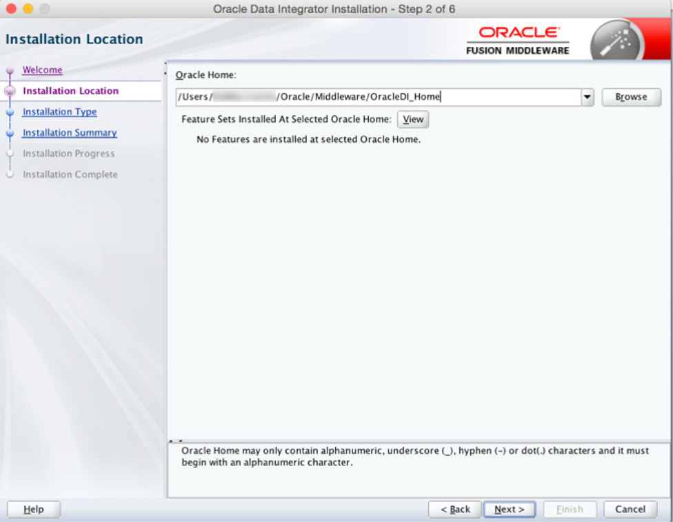
FIGURE 5-4. Oracle Home location
In the next step you tell the wizard what type of installation you wish to perform, as shown in Figure 5-5. For many cases, the default (Standalone Installation) is good enough for normal usage. The Enterprise Installation option will install additional components that can be used across the enterprise. Some of the features of the enterprise installation are the ability to make Oracle Data Integrator highly available and scalable with the integration with Oracle WebLogic Server.
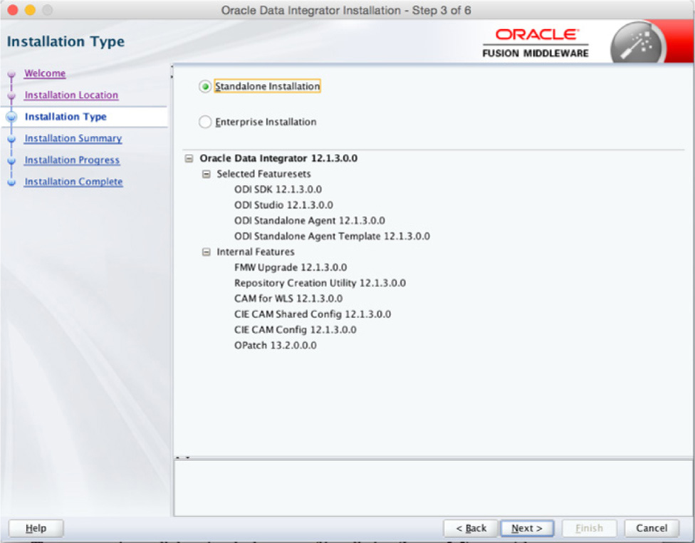
FIGURE 5-5. ODI Installation Type screen
On the next screen, the wizard provides a summary of what will be installed on the machine, as shown in Figure 5-6. At this point, the wizard is ready to install Oracle Data Integrator on the machine.
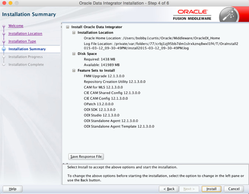
FIGURE 5-6. ODI Installation Summary screen
NOTE
Before proceeding, you should make sure everything is correct and will be installed in the location expected.
As the installation progresses, it is reported on the progress page of the wizard (see Figure 5-7).
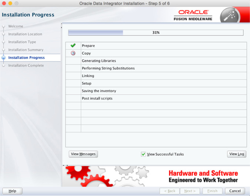
FIGURE 5-7. ODI Installation Progress screen
After the installation is completed, the Next button is enabled. Click it to move to the Installation Complete screen, shown in Figure 5-8. This screen provides information relative to the installation. Clicking the Finish button will close out the Installer and return to the command prompt in the window from which the Installer was run.
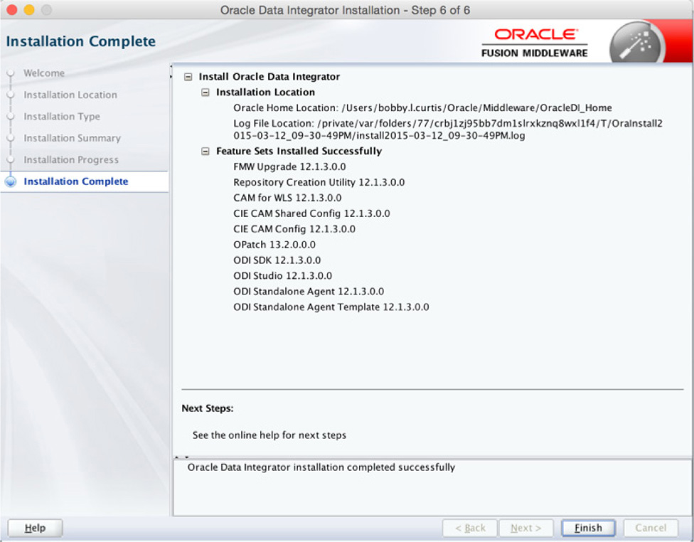
FIGURE 5-8. ODI Installation Complete screen
Once Oracle Data Integrator is installed, some additional steps need to be taken before you can start using it. These steps are to prepare the repository database and to configure the agent associated with ODI.
Preparing the Repository
Oracle Data Integrator relies on an Oracle database to be its repository. This repository is used to house the modeling schemas and work areas ODI will use. In order to prepare the repository, Oracle provides a Repository Creation Utility (RCU), which can be used to prepare a database for ODI usage. The RCU tool can be found in the oracle_common directory, located within the ODI home directory.
In order to run the RCU, you will need to navigate to the bin directory under the oracle_common directory in the ODI Home, as shown here:

After you execute the command to run the RCU, the wizard for the utility will open, as shown in Figure 5-9. Let’s walk through the wizard and configure the repository. Click the Next button to move forward.
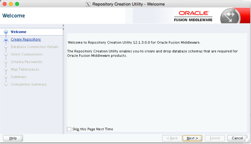
FIGURE 5-9. RCU Welcome screen
On the next screen, you are presented with a few options for creating the repository. In most cases, the organization database administrator should be running the RCU; however, there are times when you will run it. In either case, pick the option that works for the role you are providing. In this setup, you have DBA rights; therefore, select the System Load and Product Load option, shown in Figure 5-10 and then click Next.

FIGURE 5-10. Selecting the ODI repository type
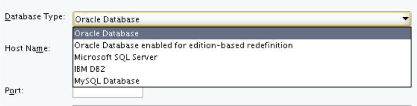
On the next screen, shown in Figure 5-11, you need to provide database connection information. This is so the utility can make a connection and build the repository within the chosen database.
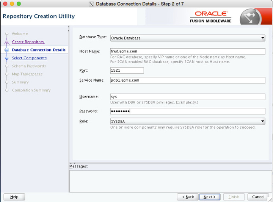
FIGURE 5-11. Database Connection Details screen
NOTE
Notice on this screen that you can use other database types besides Oracle as the repository for Oracle Data Integrator.
After you click the Next button, the RCU starts to check for prerequisites. If the database is not configured to use AL32UTF8, a warning will be displayed. Depending on your configuration, this warning can be ignored—although it is strongly recommended that you use AL32UTF8, as shown in Figure 5-12. Using a common character set provides more flexibility, and the metadata can be integrated with other systems easier.
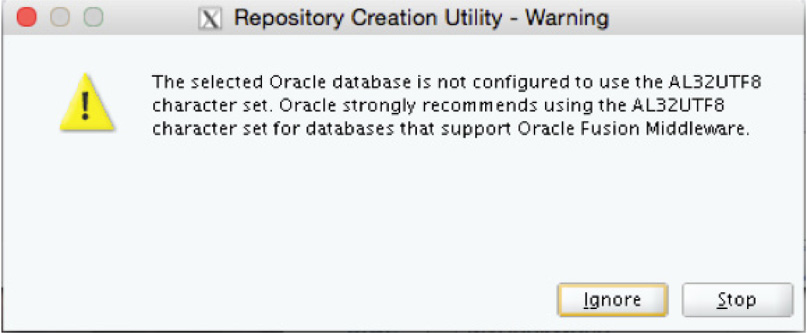
FIGURE 5-12. ODI prerequisites check
The next screen of the wizard allows you to select what components are to be installed in the repository. Because you are setting up the repository, make sure you check the option for Oracle Data Integrator. By default, this selection should select the sub-option of Master and Work Repository, shown in Figure 5-13. This screen also shows you the schema owner under which the repository will be created; in this case, the schema owner is DEV_ODI_REPO. This is the default schema generated by the RCU for the repository.

FIGURE 5-13. Selecting the ODI repository
The wizard moves to the next screen, and you are presented with the opportunity to create a password that will be used within the repository. You have three options to choose from: the simplest one is to use the same password for all schemas in the repository, as shown in Figure 5-14. The other options allow you to associate different passwords for auxiliary schemas or different passwords for all associated schemas. Depending on your security requirements, these other options could be helpful.

FIGURE 5-14. Setting the ODI password
The following screen asks you to provide the password you want to use for the schemas in the repository; the wizard asks you to provide inputs for the master and worker repositories, as shown in Figure 5-15. These options allow you to set the password for Supervisor and WorkRep users who will interact with different layers in the repository. Remember that the users of the repositories are going to be different, so providing separate access or another way to manage the access would be a reason to use different passwords.
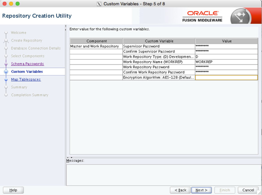
FIGURE 5-15. Setting the passwords for the ODI master and worker repositories
Part of setting up the repository also includes establishing tablespaces that will be used for the repository to store objects that will be mapped and transformed. This is done in the RCU Wizard, as shown in Figure 5-16. Here, a tablespace can be assigned to be used for master and work repository access as well as for the Common Infrastructure Object.
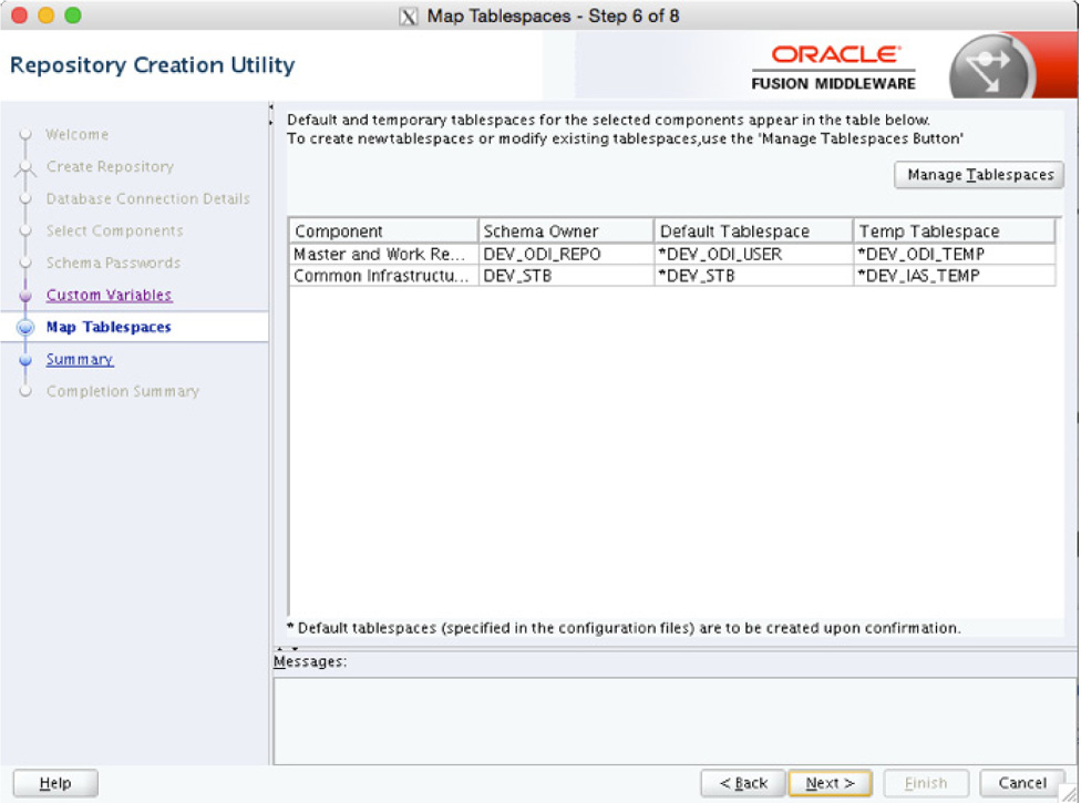
FIGURE 5-16. ODI repository tablespaces
NOTE
The RCU makes the assumption that the default naming of tablespaces will be done by the utility. These names are identified by the asterisk (*) next to them.
If the default tablespace names are not acceptable or you have predefined tablespaces for Oracle Data Integrator, select them on this screen. After you click Next, the wizard will ask for confirmation that you want to create these tablespaces, as shown next. The wizard will not progress until confirmation is received.
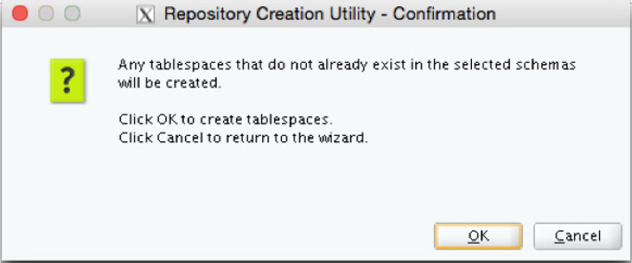
The OUI will create the tablespaces DEV_OUI_USER and DEV_STB. These tablespaces are associated with the schemas that will own the master and work repositories that Oracle Data Integrator will use.
After you confirm that the tablespaces can be created, the wizard begins to create them. A dialog like the one shown in Figure 5-17 will be displayed and will show how long it takes to create the tablespaces.
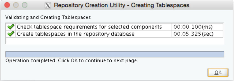
FIGURE 5-17. Creating the ODI tablespaces
With the tablespaces created, the wizard moves to the Summary screen. On the Summary screen, you can review what all will be installed and where Oracle Data Integrator will be installed, as shown in Figure 5-18. After you click the Finish button, a dialog appears that states how long it will take to install each part of the repository.
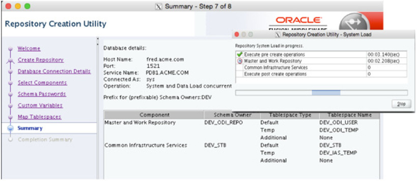
FIGURE 5-18. ODI installation summary
When the repository is done being built, the wizard moves on to the Completion Summary screen. From this screen, shown in Figure 5-19, you can review everything that has been done with building the repository.

FIGURE 5-19. Completion Summary screen
Verifying the Repository
After the Repository Creation Utility (RCU) has completed, the associated schemas can be verified from SQL. Using any tool that runs SQL and connecting as a privileged user, you can query the database to confirm the creation of the repository. For example, the following query to the registry table can be used:
![]()
NOTE
The user that can query the schema_version_registry is a privileged user such as SYS or SYSTEM.
Next, query for the object count in the master and work repository, like so:

With these two queries returning successful result sets, it can be confirmed that the repository database has been set up and is ready to use.
Configuring the ODI Agent
Just like many other Oracle products, Oracle Data Integrator uses an agent—a Java Virtual Machine (JVM) process—that runs on your data warehouse, WebLogic Administration Server, or a server somewhere on the network. The main purpose for this agent is to generate all the required scripts and SQL needed to complete extract, transform, and load (ETL) jobs and then coordinate the execution by the operating system and database. Agents allow various data sources to provide access for the integrations.
To configure the ODI agent, you need to open a terminal window and execute the config.sh script:

For simplicity purposes, let’s deploy a standalone agent. After you execute the config.sh script, the Fusion Middleware Configuration Wizard will begin.
NOTE
If you are familiar with WebLogic Server, the config.sh script is the same utility that is used to create a new WebLogic Domain.
The wizard will walk you through setting up a new domain that can be used locally. Figure 5-20 shows that the defaults are used to create a new domain. Because this is a new agent configuration, a new domain will be set up. On this page of the wizard, you also have the option of moving the location of the domain that will be configured.
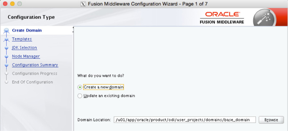
FIGURE 5-20. New domain defaults
On the next page of the wizard, shown in Figure 5-21, you will be asked to select what type of template you want to use. Because this is a standalone agent, the option Oracle Data Integrator – Standalone Agent is what you need. You will also notice that the wizard is going to configure a basic standalone domain with a local WebLogic server and that more options appear in the navigation menu to the left.
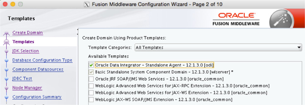
FIGURE 5-21. Selecting the ODI agent template
After you select the template for the agent, the wizard needs to know what Java Development Kit (JDK) to use when starting the agent, as shown in Figure 5-22. The wizard, by default, will select the JDK that was used to install Oracle Data Integrator. If this is not your desired JDK, you have the option to change it. In most cases, the default is sufficient for the agent to use.

FIGURE 5-22. Selecting the Java Development Kit for ODI
Next, the wizard looks for specific information on connecting to the database where the repository is configured, as shown in Figure 5-23. By default, the wizard uses information that was used with the Repository Creation Utility (RCU) earlier. Before proceeding with the wizard, you need to confirm or adjust these settings. Click the Get RCU Configuration button to validate the connection to the repository for ODI.

FIGURE 5-23. Setting the database connection
Next, the wizard connects to the repository and validates the JDBC component schemas (see Figure 5-24). These schemas will be used to make connections to the database and work with data later in the chapter.

FIGURE 5-24. Schemas for JDBC
On the next screen, the wizard tests the JDBC components. If the components are successfully tested, you should see green check marks, as demonstrated in Figure 5-25. These check marks indicate that connections to the database will be successful with the ODI agent.
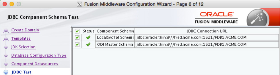
FIGURE 5-25. JDBC Test screen
After the JDBC components have been successfully tested, the wizard will ask you to provide system component information for the agent itself, as illustrated in Figure 5-26. On this screen in the wizard, just about anything can be changed; however, the defaults will work for simple environments and will provide a good start for basic integrations. As the requirements change and different components are needed, you can make changes to the environment.

FIGURE 5-26. Providing information on the JDBC components
Next, you will be asked for server connection information. On this wizard screen, you only need to provide the correct hostname where the repository is located and a password, as shown in Figure 5-27.
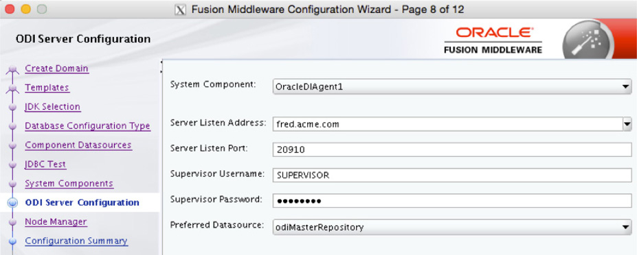
FIGURE 5-27. Providing the connection password
The next wizard page is for the node manager (see Figure 5-28). In most cases, the default option can be used; just provide a username and password to proceed.
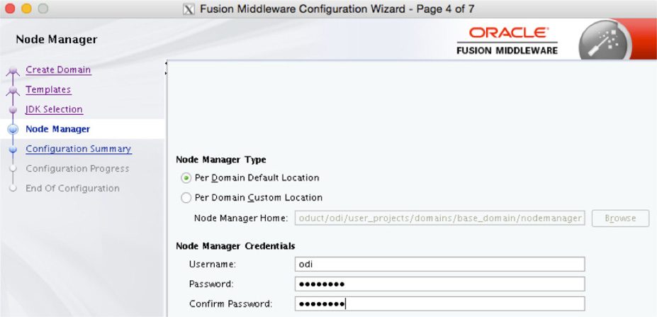
FIGURE 5-28. Node Manager screen
Finally, on the Configuration Summary screen shown in Figure 5-29, you will see what is to be created for the ODI agent. If everything looks okay, click the Create button to install the agent and move the wizard to the progress page.
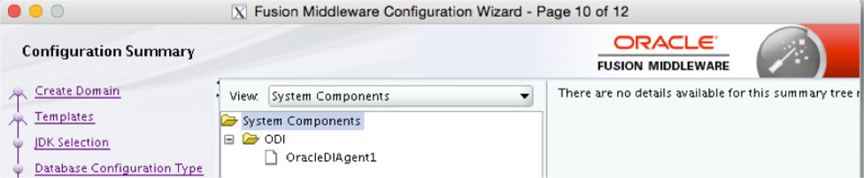
FIGURE 5-29. ODI Agent Install Summary
Once the wizard completes, as shown in Figure 5-30, the agent is ready to be used.

FIGURE 5-30. Agent installation complete
Now that the agent is installed and configured, you have the option to keep it running or to have it restart upon server reboot. Think about the automation of the processes when configuring agents and how they will be started. Even though a manual option is available, especially for troubleshooting, in order to have the processes continue, you should have the agent started upon reboot. The options are as follows:
![]() Starting and stopping the agent manually
Starting and stopping the agent manually
![]() Scripts
Scripts
Starting Manually
Just like many other processing with Oracle products, the agent can be started or stopped using a command-line utility. Since you installed a standalone agent, you will have to start it in order to begin using it. To do this, you need to use the agent.sh script located in the $ODI_HOME/agent/internal/bin directory:

NOTE
Be aware that –NAME must be in all caps, and the name of the agent is case-sensitive.
Once the agent has been started, the Oracle Data Integrator Console can use it to interact with the data points needed for the mappings.
Scripting Startup
As with anything you can do from the command line, the commands to start the agent can be placed into a script. The point of placing these commands into a script is to allow for automatic restarting of the agent upon reboot of the server. This can be done with a simple shell script (on a Unix systems) or by configuring the script as a service (on Windows systems).
Starting Oracle Data Integrator
With the Oracle Data Integrator binaries installed, the repository built, and the associated agent running, the last thing to do is to start using Oracle Data Integrator Studio. The ODI Studio is the main development and monitoring platform for working with ODI objects. It connects to a metadata repository, typically outside of the main data warehouse, to read and write data to the repository for ETL execution. When a job is run from ODI, the ODI agent connects to the metadata repository to determine what steps are needed to execute the various integration jobs.
ODI needs to be started from the command line, as shown next. The ODI binary is a shell script that calls the correct options for the platform where it is run.

After you execute the command, the ODI Studio will start and present you with an interface that is used to build objects within ODI (see Figure 5-31).
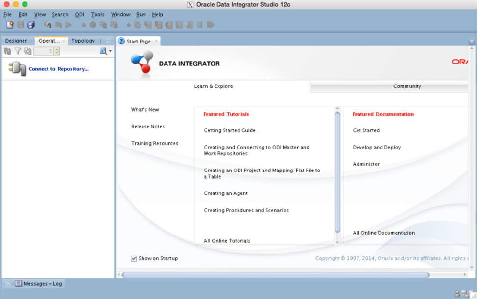
FIGURE 5-31. ODI Studio Interface
Once ODI Studio is running, the next thing to do is to build connections to the master and work repositories.
Setting Connections
With Oracle Data Integrator being the graphical tool for repository designs, operations, and topologies, you can have multiple connections to several work repositories. These work repositories can be for development (DEV) and production (PROD). ODI also allows you to retain everything in one work repository. In either case, connections have to be established to the repositories being used. Business users have read access to these repositories to validate the rules along with the results of the data integrations.
Oracle Data Integrator can be configured to use a wallet to manage all the user IDs and passwords needed to make connections to one or more work repositories. Security is important for these repositories. They need to be restricted, allowing only the users to have access to the data according to rules each user has. The security prevents unauthorized access to the datastores and business rules.
Initial Connection and Wallet Configuration
After starting Oracle Data Integrator, you need to establish connections to the repository. On the left side of the IDE you see three tabs: Designer, Operator, and Topology (see Figure 5-32). Ensure you are on the Topology tab; directly below the tab you will see the option Connect to Repository.
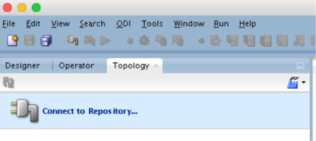
FIGURE 5-32. The Designer, Operator, and Topology tabs of the IDE
Clicking the Connect to Repository link brings up the Oracle Data Integrator Login dialog, shown in Figure 5-33. This screen allows you to create, edit, and delete logins that will be stored for use in Oracle Data Integrator. Because you will be setting up a new connection, click the plus sign to add a new connection.
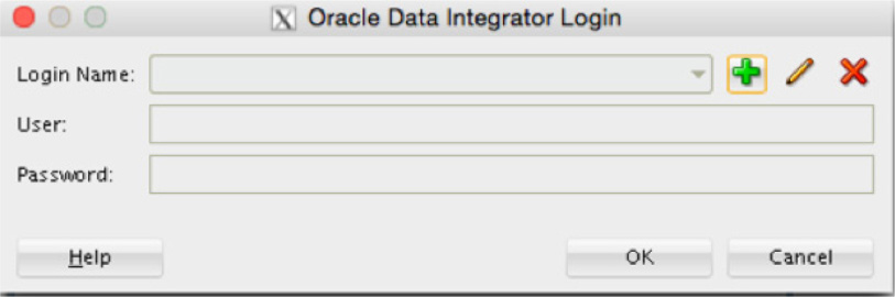
FIGURE 5-33. ODI Login dialog
After you click the plus sign, the Repository Connection Information dialog opens, as shown in Figure 5-34, and requests a lot of information. Fill in these fields with information specific to your environment.
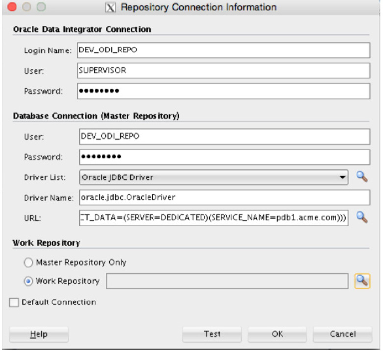
FIGURE 5-34. Repository Connection Information dialog
NOTE
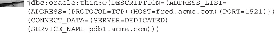
If you are using Oracle Database 12c Pluggable Databases as your repository location, the typical JDBC connection string will not work. This is because the pluggable databases’ SID is masked as a service name in the listener. To get around this fact, a JDBC connection can use a complete TNS connection string:
In the Work Repository section of the Repository Connection Information dialog, use the magnifying glass to select the work repository this connection is for. Clicking the magnifying glass opens the dialog shown in Figure 5-35, where you can select the work repository to assign.
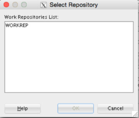
FIGURE 5-35. Selecting the work repository
After selecting the work repository to assign to the connection, you can test the connection to ensure that it works and is usable. If the connection is successful, click OK to save the connection.
After you create the first connection in Oracle Data Integrator, the studio asks you to create a new wallet password (see Figure 5-36). The wallet password is used to provide more secure access to the passwords stored in ODI. This is an optional item and can be set to be used without a secure password as well.
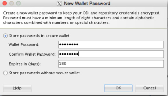
FIGURE 5-36. Creating a new ODI wallet password
NOTE
After you create the wallet, it will be stored in a hidden directory in your home directory (~/.odi/oracledi/ewallet). The wallet can be viewed from Oracle Wallet Manager (OWM). The wallet is not removed automatically if you uninstall ODI.
With the connection to a repository set up, a connection can be made within Oracle Data Integrator. If the connection is successful, you will have information under all the tabs on the left side of ODI, as shown in Figure 5-37.
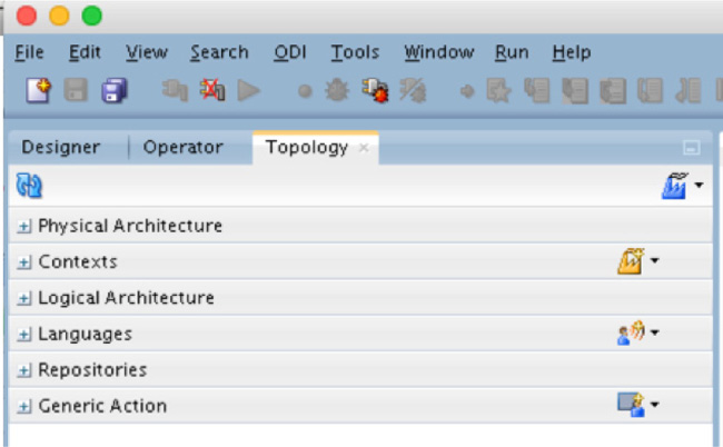
FIGURE 5-37. ODI tabs after connection
After configuring and then making the connection, you will need to build out the topology to integrate your data.
Configuring a Topology
Topologies are how you map your data to physical and logical mappings. Defining the rules as part of the topologies will allow for a review after the data integration is performed. Based on the mappings and the data sources, topologies might have to go through some iterations to verify and validate. The physical data have the actual connections to various data sources, which include the integration of that data. The physical mappings use the different technologies and agents that have been installed. The logical mappings are for defining the business rules and how the data should be configured to be mapped together.
Physical Architecture
A physical architecture is the mapping that defines the physical aspects of the data to be integrated. When you open the Physical Architecture context menu, the tree that’s shown consists of Technologies and Agents (see Figure 5-38).
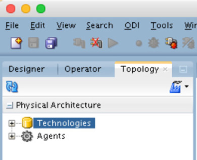
FIGURE 5-38. Technologies and Agents
When you expand the Technologies tree, ODI provides a list of all the technologies that are supported for mapping the physical architecture (see Figure 5-39).
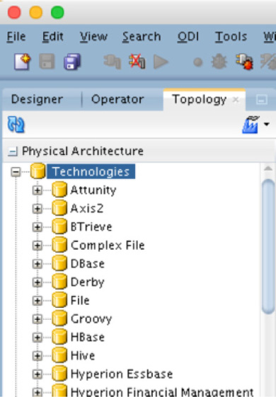
FIGURE 5-39. Technologies tree
Because you will be working with flat files for importing data, you will be interested in the File technology. Let’s take a look at how to configure this technology to be used with flat files.
Configuring a Flat File Physical Schema
To create a physical architecture for a flat file, you need to select the File option and then select Open, as shown in Figure 5-40. This will open the display panel to the right, where you can fill in the specifics of the physical architecture.
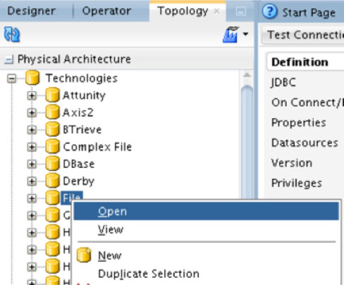
FIGURE 5-40. Configuring a file schema
On the display page, the only required items to be entered are the Name and Host (Data Server) values, as demonstrated in Figure 5-41. The value for Name can be generic in nature. The value for Host (Data Server) can be either localhost (if you are running ODI from where the flat file is located) or the DNS name of the server where the flat file is located.
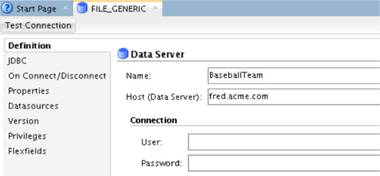
FIGURE 5-41. Defining the data source
Once these items are configured, you can then save your settings. Before your settings will be saved, ODI will ask you to test the connection to the server specified in the Host (Data Server) field. Part of this test will be the interaction with the default agent. You can use the default local agent, or you can specify the agent you created earlier in the chapter.
Once the new data server has been created, you will need to create a new physical schema, as shown in Figure 5-42. This will open the properties page to the right, where the mappings to the file can be made.
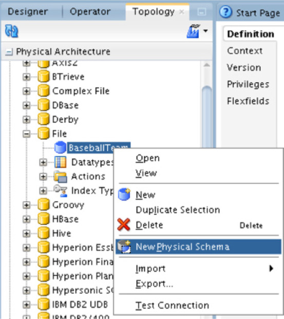
FIGURE 5-42. Creating the physical schema
On the properties page, the Directory (Schema) and Directory (Work Schema) fields need to be populated. Although these are drop-down menus, they will not be populated with anything; however, you can highlight them and type in the needed values, as shown in Figure 5-43. Type the location of where the flat file is located on the data server. In Figure 5-43, you see that the same directory can be used for both items (in this case, /tmp).

FIGURE 5-43. Specifying the physical schema definition
Everything else on the properties page can be left at the default settings. After saving the properties, you will notice that the physical schema is now built under the data server in the Physical Architecture context menu, as shown in Figure 5-44.
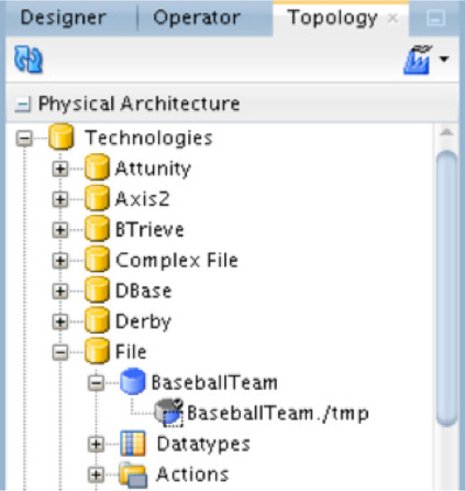
FIGURE 5-44. File schema created
Once the physical data server and schema are created, you will need to map a logical architecture.
Logical Architecture
After you configure the physical architecture objects, you need to configure the logical architecture needed for flat file ingestion. In order to do this, you will remain in the Topology tab and select the Logical Architecture context menu. Just like the physical architecture, you will see a Technologies tree option, as shown in Figure 5-45. Expanding this tree will display all the technologies that can be mapped at the logical level.
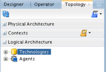
FIGURE 5-45. Logical schema technologies
A logical schema is a logical abstraction of the physical entities being used within the data mappings.
To map a logical architecture, you need to define a new logical schema. This can be done by expanding the Technologies tree, opening the File technology, and requesting a new logical schema (see Figure 5-46).
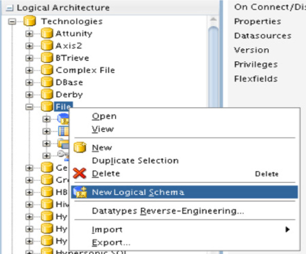
FIGURE 5-46. Creating the logical schema
The new logical schema properties page opens to the right. This is where you can name the logical schema and point it to the physical schema mapped earlier. The logical schema can be named anything you desire, as demonstrated in Figure 5-47.
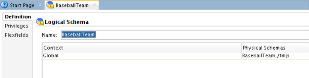
FIGURE 5-47. Logical schema naming
The important thing to note on this properties page is the Context and Physical Schemas information. These two pieces of information allow you to control where the files to be ingested are located and help in stabilizing the mapping framework.
With both the physical and logical schemas mapped to the location of the files to be ingested, the next step in the process is the design where the data goes.
Designing Models
The previous sections laid out the physical and logical schemas that will be used to process the data in flat files. The next step is where the fun with Oracle Data Integrator begins. Until now, everything has been about setting up the framework that will be used. The designing phase allows you to read in the potential data and later process that data to a target. Keep in mind that you are using Oracle Data Integrator as a data flow modeling tool. Let’s get started with designing how you will read a flat file into the data flow process.
NOTE
Oracle Data Integrator is a data flow modeler, not a data structure modeling tool. If you need to model the structure of the data, look at tools such as SQL Developer Data Modeler.
In the Designer tab, context menus for the following can be found:
![]() Projects
Projects
![]() Models
Models
![]() Load Plans and Scenarios
Load Plans and Scenarios
![]() Global Objects
Global Objects
![]() Solutions
Solutions
These context menus are used in all areas of the design and development phases when working with data. To keep with the simple example we are walking though, you only need to worry about building a model at this point. In order to do this, select Models, as shown in Figure 5-48. This will open a blank context menu.
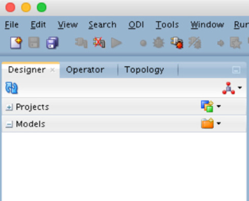
FIGURE 5-48. Designer models
NOTE
To make management of models easier, it is best to create folders for different models.
After opening the Models context menu, you need to create a new model. This can be done by either right-clicking, as shown in Figure 5-49, or from the folder option on the same line as the item name.

FIGURE 5-49. Selecting New Model from the context menu
By selecting the New Model menu item, you cause the properties page for a new model to open to the right of the context menu, as shown in Figure 5-50. On this page, you can add a name for the model and select the technology that should be used. Other items on this page can be ignored or will be configured based on your selections in the dialogs.

FIGURE 5-50. Creating a new model
After you save the model, it will show up in the context menu. If you have created a model folder, the model will appear in the folder.
With a model now defined, a datastore needs to be defined for the model; this is done by accessing the right-click menu and selecting New Datastore, as shown in Figure 5-51. Just like with the other menu selection, a properties page will open on the right side of the Studio.
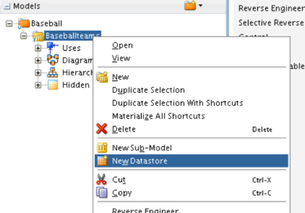
FIGURE 5-51. New Datastore option
On the properties page are three main areas you need to address: Definition, Files, and Attributes. Each area helps in describing the datastore, what flat file should be used, and any attributes that need to be configured for the data.
The Definition area is where the datastore’s name, alias, type, and resource are defined. You can name the values on this page anything you desire. Defining a naming convention would make sense in order to have consistency for the definitions and the ability to match up with mappings. Standards should be set up for all the definitions with physical and logical modes. The resource name needs to point to the flat file that will be read in order for the data to be loaded, as shown in Figure 5-52.

FIGURE 5-52. Resource file for load
The File area is where you describe the file being ingested, as demonstrated in Figure 5-53. Part of the description tells Oracle Data Integrator the file format, whether any line is a header row, what type of record separators are used, and how the fields are separated.
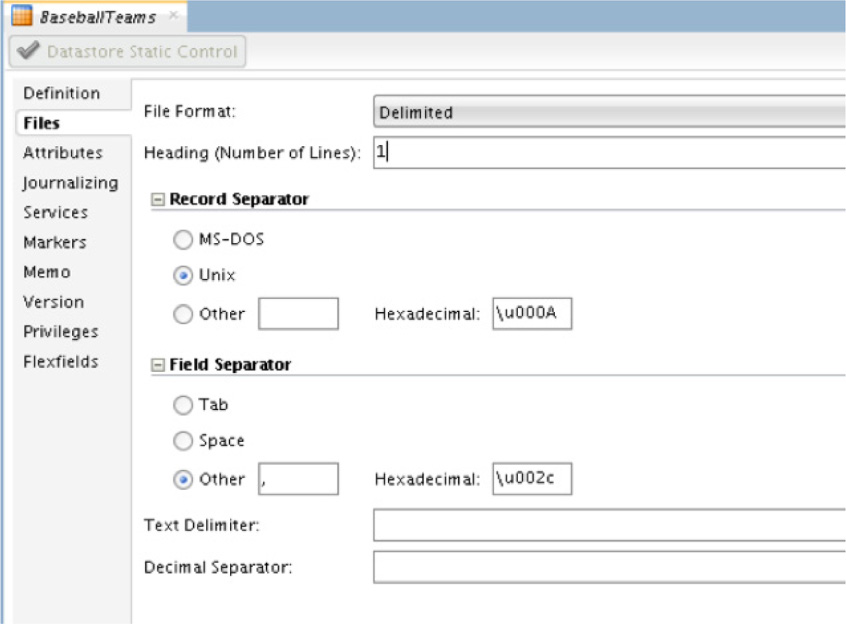
FIGURE 5-53. File description for ODI
After describing the file to be ingested, save the datastore. Upon saving, you should be prompted with a dialog about locking the file. This is normal and can be dismissed by saying yes as shown here:

After clicking yes, notice in the menu that the datastore now has a lock next to it. This means that no one can make changes to the file while it is being ingested.
The third area to be concerned about on the properties page of the datastore is Attributes. The Attributes page is where the reverse engineering happens and the data in the flat file is validated. With the datastore saved, the Reverse Engineer button is available to be selected. Selecting the Reverse Engineer button will review the file and provide the headers that appear in the flat file associated with the datastore (see Figure 5-54). At this point, the source datastore is configured and ready to be used.

FIGURE 5-54. Data source attributes
NOTE
If you want to see the data in the datastore, right-click the datastore and select View Data. This will provide the data associated with the datastore.
Target Side
The target side of the integration process is where the database tables reside and where the flat file’s data will be written. To set up the target side in Oracle Data Integrator, you follow the same process as you did for the flat files: Physical Architecture, Logical Architecture, and Model. The difference this time is that these attributes are laid out using database technologies instead of a file technology.
Create a Database Physical Schema
To set up a physical schema for a database, select the database type from the Physical Architecture menu. In the example, you will be working with an Oracle Database. Find the desired database type in the menu, right-click it, and add a new data server to the architecture, as shown in Figure 5-55.

FIGURE 5-55. Creating a new data server
On the right side of the Studio, the properties page opens. On this page, you provide a name for the database and what instance you want to connect to. Unlike the flat file physical architecture, to make the connection to a database, you must provide the username and password, as shown in Figure 5-56.
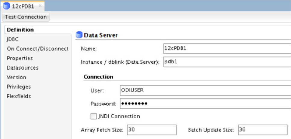
FIGURE 5-56. Login for the data source
Additionally, before a connection can be made to a database, you need to select a drive. Oracle Data Integrator allows you to use JDBC to make the connection the database. While still on the properties page, select the option for JDBC. Once on the JDBC page, make sure to select the correct drive for Oracle and then provide the connection string to connect to the database. Figure 5-57 shows an example of this.

FIGURE 5-57. Test connection
Lastly, you need to test your connection. Oracle Data Integrator will ask what agent to use. The local agent is fine to use. If everything works as expected, the connection should be successful.
After successfully setting up the data server for the database in a physical architecture, the next thing needed is a physical schema that can be mapped. In order to do this, you need to create a new physical schema under the data server just created, as shown in Figure 5-58. This will open the properties page again, where you can add details related to the physical schema.
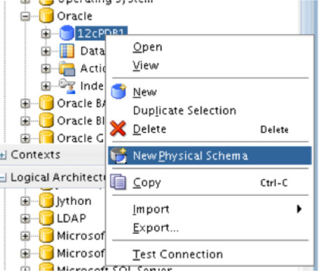
FIGURE 5-58. Creating a new physical schema for the data source
In the details of the properties page, you will need to provide a schema and a working schema and then save the physical schema. Figure 5-59 highlights what needs to be added to the properties page.
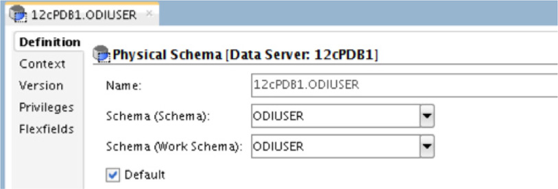
FIGURE 5-59. Physical schema definition
Once the physical schema has been created and saved, the logical schema can be built too.
Creating a Database Logical Schema
Building a logical schema for the database is done the same way as before. Under the Logical Architecture menu, find the database that is needed. Once the database type is identified; right-click and select the New Logical Schema, as shown in Figure 5-60.
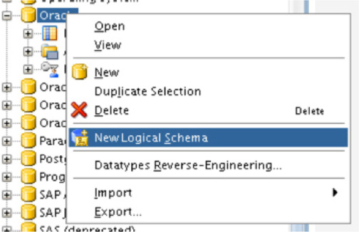
FIGURE 5-60. Creating a new logical schema for the data source
On the properties page in the Studio, name the logical schema and provide the physical schema as the global context for the schema. Figure 5-61 illustrates this process.

FIGURE 5-61. Setting the global context for the schema
Now that a physical schema and a logical schema have been created for the Oracle database, you can move back to the fun stuff—modeling the data on the Designer table.
Adding a Database Data Model
Adding a model for a database is done in the same way as you did for the flat file. Earlier, you may have created a folder to hold your previous model; if so, you can create the database model in the same folder. Once you have two or more models built, we will start to look at how mappings are done. For now, let’s create the database model as we have done for the flat files.
In the Models menu, right-click or select your folder and then right-click and select New Model. This is illustrated in Figure 5-62. After you select the New Model option, the properties page will open on the right side of the Studio.
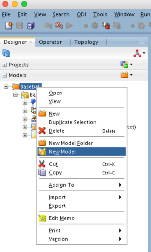
FIGURE 5-62. Creating a new model for the data source
This model is similar to the flat file model, but there are a few differences because we are using a database technology instead of a file technology. Fill in the properties page by providing a name for the model and then select the technology for the model. Everything else should then populate, as shown in Figure 5-63.

FIGURE 5-63. Model definition for the data source
After you save the model, it will appear in the Models menu. Now you can move to the Reverse Engineer page of the properties page. From here, Oracle Data Integrator will reverse engineer the schema selected in the physical architecture. Once the schema has been reversed engineered, the object associated with the physical architecture will appear in the model, as shown in Figure 5-64.
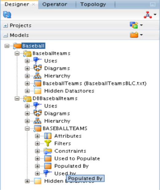
FIGURE 5-64. Physical architecture with the model
NOTE
With the tables pulled into the model, if you want to look at any data that may be in the table, you can do so using the View Data option in the right-click menu for models.
With all the physical, logical, and models created, the majority of the heavy lifting has been done to integrate the flat file discussed earlier. What needs to be done next is to build the mappings that will ensure successful data integration from flat file to database.
Mappings
Now that all the heavy lifting is done with defining the schemas and connections, the question is, how can you map the data between the flat file and the defined database table? The answer is quite simple: by creating a project. Projects are defined in the menus under the Designer table. Projects will group the data sources and models to be used together. The standard naming convention should be used—from the projects down to the data sources—to make creating the project easier once all the pieces are in place. Overall, projects should be reviewed for business requirements, which might just be adding a new data source or model for changes. You can even remove a data source if it becomes obsolete. Managing the projects is part of gathering and maintaining the data integrations.
Creating a Project
Before any mappings can be done, you must define a project. Using the Projects menu under the Designer tab, select New Project to open the properties page to define the new project, as shown in Figure 5-65. On the properties page, provide a name for the project and then save it. The project will then appear in the Projects menu.

FIGURE 5-65. New project creation
With the project created, notice that a First Folder menu item appears. Expanding this folder will provide a list of sub-objects for the project. Figure 5-66 is where you will see the Mappings option.
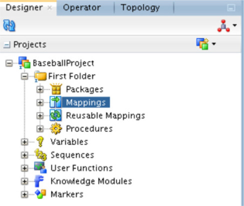
FIGURE 5-66. Project mappings
Under the Mappings option in the tree you will find no current mappings. Right-click Mappings to bring up the menu item shown in Figure 5-67. Select the New Mapping option to define a new mapping.
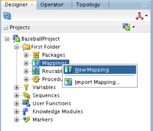
FIGURE 5-67. New mapping definition
The first thing you are asked when defining a new mapping is what the name of the mapping should be. Because this is a mapping from a flat file to a single database table, at this point, make sure you uncheck the Create Empty Dataset option after naming the mapping. Next, Oracle Data Integrator will switch views to provide a navigator to use for modeling, as shown in Figure 5-68.

FIGURE 5-68. Creating an empty data set
From the mapping navigator, you can drag the models over the table structures that will be mapped. Figure 5-69 provides what this view should look like for mappings between the flat file and database table.
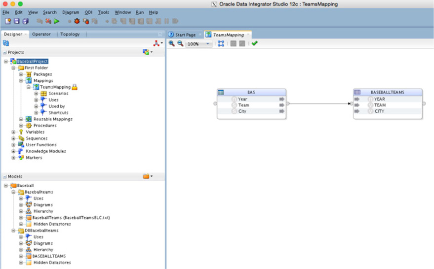
FIGURE 5-69. Mapping navigator models
Once the tables you want to map are in the navigator space, they can be linked using the small circles between the boxes. Once the mappings have been established, you will see grey arrows that indicate whether the columns were successfully mapped.
With successful mappings in place, at the bottom of the navigation screen you will see a series of tabs, as shown in Figure 5-70. These tabs provide different views of the mapping that are shown in the navigation display. Initially, you will be placed on the Logical tab. This table shows you the data flow mappings between the objects you have placed in the logical model. This is similar to a traditional data model, but it highlights the mapping relationship between the objects instead of the relational relationship.

FIGURE 5-70. Mappings for the data sources
Select the Physical tab at the bottom of the page. This changes the display of the mappings. This now shows more detail for the interfaces used for mapping the data flow between the objects. The interfaces shown in Figure 5-71 are how Oracle Data Integrator will map the flow of data during execution.
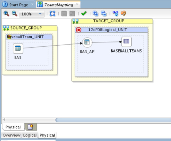
FIGURE 5-71. Interfaces of the map flow
Click the access point, BAS_AP (the circle icon), in the physical display of the mapping; the properties of the access point can be edited, as illustrated in Figure 5-72. For the most part, the properties do not need to be edited, unless there are other knowledge modules you want to use.
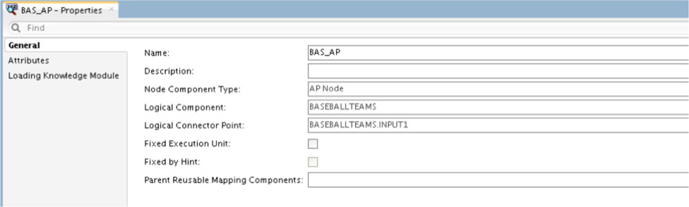
FIGURE 5-72. Editing the general properties
After the mappings have been established, the final step in the process is to run the them. Although the mappings can be executed at this point, you should take some time to look around the physical model. If you examine the BASEBALLTEAMS icon, you will notice what integrated knowledge modules (IKMs) are used to process the data, as shown in Figure 5-73.
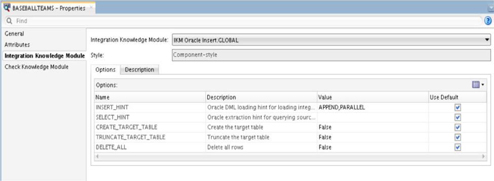
FIGURE 5-73. Integration knowledge module
As illustrated in Figure 5-73, the integrated knowledge module is a predefined setup of steps the ODI uses to ensure that data is integrated correctly. There are many different types of knowledge modules and the usage of these modules ranges across the ELT processes. Knowledge modules are used to help ODI expand its reach into other technologies such as Big Data. Although we will not dive deeply into knowledge modules here, know that knowledge modules provide a wide range of flexibility and support to the ELT process.
Running the Mappings
Running the mappings is pretty simple. You have a few different ways to run the mappings once they are established. Here are the ways to execute the mappings from within the Oracle Data Integrator Console:
![]() Using the Run command in Studio
Using the Run command in Studio
![]() Using the Run command in the right-click menu
Using the Run command in the right-click menu
![]() Using the Run command from the Run menu
Using the Run command from the Run menu
NOTE
Mappings can be run in multiple ways, including execution via a shell script or via a web service call.
The simplest way is to highlight the mapping in the Projects menu and then select the green arrow from within the Studio. Figure 5-74 shows the location of the green arrow in the Studio (under the Search menu).
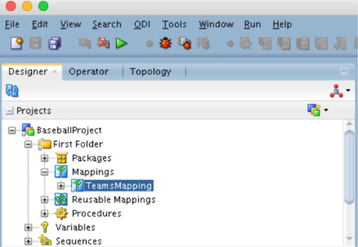
FIGURE 5-74. Running the project
Once the Run command has been executed, a dialog will display asking for additional information before actually running the mapping. The items it will ask for are related to the environment in which you would like to run the mapping, as shown in Figure 5-75.
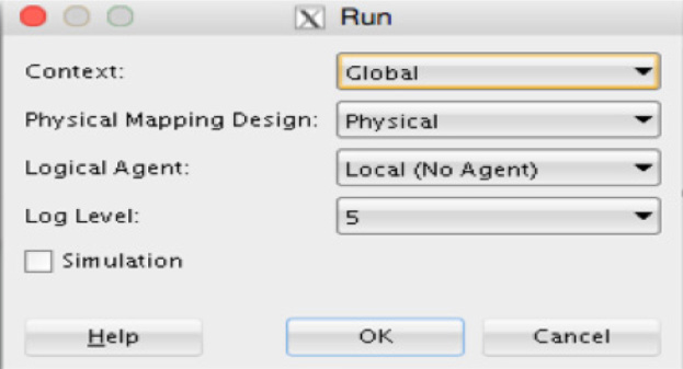
FIGURE 5-75. Defining the Run Environment
The options provided in the Run dialog are related to the context, physical mapping, logical agent, and log level for the execution. With the configuration that has been established to this point, the default settings in the Run dialog will be used.
Once the run is executed, Oracle Data Integrator will check the mappings for validations and proceed to run the mapping, which will integrate the data from a flat file into a database table.
Simulation
You will notice on the Run dialog box a check box labeled Simulation. If you check this box, the execution of the mappings will run in a simulation mode, where you will be presented with output of what the mappings will do. Figure 5-76 presents the output of executing the baseball mapping.
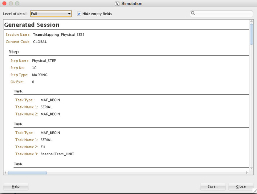
FIGURE 5-76. Simulation of data mappings
When the simulation is done running, you can save the output for future reference. This provides a way for you to validate your mappings without actually executing them against live data or production architectures.
When saving the simulation report, you can choose to save the information in either an XML file or an HTML file. Either option provides you with a way to save the output in a user-friendly format.
Step-by-Step Execution
The Oracle Data Integrator Console provides you with many ways to review your mappings. Another valuable tool that is provided is the ability to debug a mapping. By running the mapping in Debug mode, as demonstrated in Figure 5-77, you can have the execution stop at different breakpoints or stages within the process.
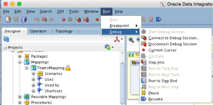
FIGURE 5-77. Debug mode for mappings
When running in Debug mode, the Console provides you with a tab section that highlights each step as it is processed (see Figure 5-78). This allows you to see exactly where the execution is within the process.

FIGURE 5-78. Stepping through Debug mode
As you can tell, when you execute a mapping, you can see many different aspects of its execution. By giving you all these different views into how the execution is being handled, the Oracle Data Integrator Console becomes a valuable tool for all users who interact with it.
Validating That the Data Has Been Integrated
After the mappings have been run, you have multiple ways to validate that the data was ingested and inserted into the table as described in the mapping. The simplest way is to use any SQL tool to connect to the database and then select from the table to see if the date exists. In Figure 5-79, SQL Developer is used to check the tables in ODIUSER.BASEBALLTEAMS to see if the data was successfully added.

FIGURE 5-79. Using SQL Developer for verifying data
As you can see, the data from the flat file was successfully mapped to the BASEBALLTEAMS table in the odiuser schema. This same data can also be verified from within Oracle Data Integrator by using the model that was defined for the BASEBALLTEAMS table.
Summary
Many tools available on the market claim to do data integration for many different data types. We only covered one type of integration with Oracle Data Integration in this chapter; however, Oracle Data Integrator does so much more than just integrations from flat files to database tables. With the ever-growing amount of data in the industry, Oracle has set Data Integrator apart by making it a robust tool that can transform data—from a flat file all the way up to interactions with Big Data environments. It is recommended that you take some time and dive deeper into what Data Integrator can do above and beyond what you have read in this chapter.
Using the proper access to the different repositories and verification of data will allow the business users to define and validate their data integrations. This is an important part of providing the needed data to the business. Using tools to pull in different data sources simplifies the complex integrations that need to be done.
