
186 Oscilloscopes
screen current limiter
goin-coml~nsat ing 125 kV
cathode driver screen )
demagni f i er phosphor
J stigmator (P31)
I I primary focus ........ "~
I I !ostigmotism
beam
';'~ea'm" faceplote rl
I I I
limiting aperture
vert ~
~
II
!!! [ ~
I iTJ
-il
helical scan expansion ~ N
def lectors (horiz. &vert.) lens
,~I
�
MCP bias 700-1050V P31 phosphor ~--
volta-e ~
j P"
u I
FI (alumlnised) jw
~-~ ,o,v-~. I__,o..o,o~o
biam e- ~ I:i:: ~ :t:r~r
!
microchannel
plate
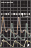
Figure 9.11 The MCP (micr()channel plate) cathode ray tube used in the
Tektronix oscillosc()pe type 7104. MCP c.r.t.s are als() used in the model 11302
mainframe and in tile 2467. This model for the first time enables an isolated glitch
only nanoseconds wide to be seen on a portable oscilk)scope. All three models
mentioned are discontinued, btlt highly valued on the second-user market
(courtesy Tektronix UK Ltd)

How oscilloscopes work (1): the c.r.t. 187
end. The wires of which the mesh is woven are so fine that it is
invisible; this also ensures that it is transparent to the beam of
electrons. Figure 9.10 shows a high-performance oscilloscope
c.r.t, with side connectors to the deflection plates for minimum
capacitance, spiral p.d.a., internal graticule, bonded implosion
guard and light guide for graticule illumination.
All the measures to maximize the bandwidth of a c.r.t.
mentioned previously- p.d.a., delay-line deflection plates, scan
expansion lenses - were put together in the cathode ray tube
used in the Tektronix type 7104 oscilloscope. This instrument
boasted a 1 GHz real-time bandwidth, this limit being set by the Y
amplifier rather than the c.r.t, itself. The latter could display
signals up to 2.5 GHz, were it possible to design suitable wideband
drive circuitry. Also, notwithstanding the conflict, explained
earlier, between tube design parameters for optimum bandwidth
and maximum writing speed, this tube achieves the remarkable
writing speed of 20000cm/lxs, using ASA 3000 film without
fogging. (In fact, single shot events at that speed can also be seen
comfortably with the naked eye.) The secret is revealed in Figure
9.11, which shows that in addition to the measures already
mentioned, the c.r.t, incorporates a microchannel electron
multiplier plate. This consists of thousands of short, parallel
tubes, each coated internally with a high-resistance film. Each
individual tube acts as an electron multiplier by virtue of
secondary emission, resulting in 10000 electrons hitting the
phosphor for each electron in the beam. Owing to the small
spacing between the microchannel plate output side and the
aluminized phosphor, together with the high potential difference
between them, there is negligible spreading of the output of each
microchannel tube, maintaining a small, sharp, spot size.
..................Content has been hidden....................
You can't read the all page of ebook, please click here login for view all page.