
228 Oscilloscopes
curve lies so near the first crossover that the whole screen will
spontaneously fade positive. Both these collector levels are
shown in Figure 1 1.6.
Turning now to the consequences of decreasing the collector
voltage below OL, we must recall that the upper stable point of
the target always occurs at a voltage in the vicinity of the collector
voltage, since it is the failure of the collector to collect which
causes the abrupt drop in the target 'balance sheet' curve of
Figure 1 1.3. Now if the collector is lowered to the vicinity of the
first crossover voltage, this will result in a curve as shown in
Figure 1 1.7, and it is clear that under these conditions there is
only one stable point, the lower stable point. The floodbeam will
return all target areas to the lower stable point; written
information is no longer retained. This collector voltage is
therefore called the retention threshold (RT).
Now we can define the stable range: it is the range of collector
operating voltages between retention threshold and fade-pos-
itive. And it is this stable range which is affected by the thickness
of the target in the manner shown in Figure 1 1.5. In itself it will
not concern us operationally, since we would be unwise to
operate the collector near either of these extreme limits. But a
large stable range will obviously provide a greater operating
-o
8
.m
~
C:
0
o_.
(/)
~
E
0 -10
normal V c
V c just below t
retention threshold f/
I j/ 1
I
9 i//
0
target voltage (relative to cathode)
curve for V c just below retention threshold
normal bistable curve
Figure 11.7 If the collector voltage is too low, it becomes impossible to store a
trace (courtesy Tektronix UK Ltd)

How oscilloscopes work (3): storage c.r.t.s 229
margin for the collector voltage. This margin is important for
several reasons:
9 Setting the collector voltage operationally to the centre of this
range is a subjective procedure which will yield a certain
spread from operator to operator.
9 In many instances the c.r.t, heater is unregulated, and varying
mains voltages can cause performance changes.
9 Storage c.r.t.s are subject to ageing effects which might, if the
operating margin is too small, require frequent recalibrations.
9 Even with best manufacturing techniques there is usually
some non-uniformity across the target, calling for different
optimum collector voltage settings, and in the presence of a
large operating margin the choice of a suitable compromise
setting is much easier.
9 For all these reasons a large stable range is so important that we
sacrifice much contrast to obtain it, as suggested by Figure 11.5.
When contrast was first mentioned as a significant factor in
connection with Figure 11.5 you may have been puzzled since it
is normally taken for granted in oscilloscopes that unwritten
areas of the screen are practically black and the contrast therefore
practically infinite. The discussion of the average rest potential
will have explained why, on phosphor-target storage tubes, the
contrast is on the contrary quite limited. But although Figure
11.5 shows a typical contrast figure of only 3:1, some improve-
ment can in fact be expected after a hundred operating hours or
so. The reason is that much background light is contributed by
those dots which have faded positive, and as these phosphor dots
operate continually at full light output they will be the first to age
and eventually burn out, leaving the unwritten part of the screen
darker. On most tubes the contrast ratio will reach 20:1 after
about 300 hours.
Operating characteristics of the phosphor-target
tube
One of the main limitations of a storage tube is its inability to
store traces if the beam is moving too fast - if it exceeds the
maximum writing speed. The bulk of this section will be

230 Oscilloscopes
concerned with the definition of writing speed, what factors
influence it and how it can be improved. Then we shall return to
the topic of erasing and see in detail how this is done.
In a bistable tube, writing is the process of raising the voltage of
those points on the target which are scanned by the writing beam
above the first crossover, despite the continuing attempts of the
floodbeam to return to the rest potential. (Once the critical first
crossover level has been passed, the floodbeam will carry them to
the written level even without any further contribution from the
writing beam.) The effect of the floodbeam is to add a given
number of electrons to unit target area in unit time. But this
number depends on the secondary emission ratio and is highest
where the 'balance sheet' curve of Figure 1 1.2 departs most from
the 8 = 1 level, trailing off to zero as the first crossover is
approached. Since we can neither measure the secondary
emission in an actual c.r.t., nor even be sure from what rest
potential the target must be lifted, it is impossible to quantify the
demands made on the writing beam if it is to achieve storage.
But the effect of the writing beam itself is also far from
straightforward. Consider first the situation of a stationary beam.
Even though it is focused, the spatial distribution of beam
intensity follows the normal Gaussian distribution curve shown
in Figure 1 1.8. At the point on the target where it peaks, the
beam density per unit target area is greatest, hence the number of
secondary electrons lost in unit time is highest. If this number
exceeds the number gained from the floodbeam action the target
,m
e-
E
distance (in all directions) across target
Figure 11.8 Electron density distribution across the beam (courtesy Tektronix
UK Ltd)
How oscilloscopes work (3): storage c.r.t.s 231
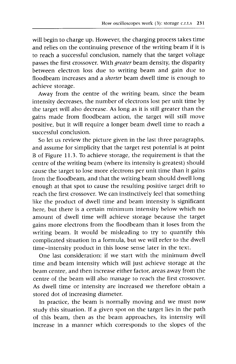
will begin to charge up. However, the charging process takes time
and relies on the continuing presence of the writing beam if it is
to reach a successful conclusion, namely that the target voltage
passes the first crossover. With
greater
beam density, the disparity
between electron loss due to writing beam and gain due to
floodbeam increases and a
shorter
beam dwell time is enough to
achieve storage.
Away from the centre of the writing beam, since the beam
intensity decreases, the number of electrons lost per unit time by
the target will also decrease. As long as it is still greater than the
gains made from floodbeam action, the target will still move
positive, but it will require a longer beam dwell time to reach a
successful conclusion.
So let us review the picture given in the last three paragraphs,
and assume for simplicity that the target rest potential is at point
B of Figure 11.3. To achieve storage, the requirement is that the
centre of the writing beam (where its intensity is greatest) should
cause the target to lose more electrons per unit time than it gains
from the floodbeam, and that the writing beam should dwell long
enough at that spot to cause the resulting positive target drift to
reach the first crossover. We can instinctively feel that something
like the product of dwell time and beam intensity is significant
here, but there is a certain minimum intensity below which no
amount of dwell time will achieve storage because the target
gains more electrons from the floodbeam than it loses from the
writing beam. It would be misleading to try to quantify this
complicated situation in a formula, but we will refer to the dwell
time-intensity product in this loose sense later in the text.
One last consideration: if we start with the minimum dwell
time and beam intensity which will just achieve storage at the
beam centre, and then increase either factor, areas away from the
centre of the beam will also manage to reach the first crossover.
As dwell time or intensity are increased we therefore obtain a
stored dot of increasing diameter.
In practice, the beam is normally moving and we must now
study this situation. If a given spot on the target lies in the path
of this beam, then as the beam approaches, its intensity will
increase in a manner which corresponds to the slopes of the

232 Oscilloscopes
distribution curve. It will reach a peak when the beam is centred
on the spot, and then decrease in a similar manner. But whether
storage will take place depends on the same considerations which
we enumerated previously: whether the maximum beam inten-
sity is great enough and the dwell time long enough. In this
situation quantitative analysis is futile. Specifications are verified
by selecting the highest beam intensity before defocusing occurs,
and increasing the beam velocity until the beam moves so fast
that there is insufficient dwell time for storage to occur. This
specification is called 'writing speed' and is typically, for phos-
phor-target tubes, 0.1 cm/~s.
If the dwell time is made longer by moving the beam more
slowly, areas to the side of the central path of the beam will
receive a sufficient dwell time-intensity product to become
written. As the beam is slowed down we therefore get a
progressively wider stored trace.
At the end of this discussion we hope that you will have an
instinctive feeling for the principal factors affecting dot writing
time and writing speed. We will now consider in what way the
writing speed, and also the brightness and contrast of the stored
display, are affected by the collector operating voltage.
The published specifications assume that the collector operat-
ing level (OL) is set normally, let us say to the centre of the stable
range in Figure 1 1.6. As we increase the collector w~ltage, leakage
increases, the average rest potential increases, and consequently
the target rests nearer to the first crossover. This means that a
lesser dwell time-intensity product will suffice to achieve
writing; holding the intensity constant we can increase the beam
velocity and still store. The writing speed specification has been
improved. But the improvement is not spectacular and the
change of collector w~ltage has other side-effects which are more
important and which we will look at shortly.
If the collector w~ltage is decreased the opposite effect takes
place. The ARP drops and the writing beam must linger longer to
achieve writing. In fact, for a specified beam velocity, if the
collector w~ltage is decreased sufficiently, a level will be reached
at which the dwell time-intensity product is no longer enough to
achieve writing. This collector voltage limit is called 'writing
..................Content has been hidden....................
You can't read the all page of ebook, please click here login for view all page.