
Appendix 2
MIDI
The term MIDI stands for Musical Instrument Digital Interface. Do not confuse it with the term Midi as applied to Hi-Fi units, which is a description of their size (Midi as opposed to Biggi). MIDI is what is known as a serial connection. The data are sent as a series of long and short pulses in groups of eight. Additionally there is a pulse on either side known as 'start’ and 'stop’ bits. Just over 30 000 of these pulses can be sent every second – 3000 ‘groups' known as ‘bytes' (31.25 kbaud in tech-speak).
The connections are via Deutsche Industrie-Norm (DIN) plugs which, although physically identical to audio DIN plugs, are differently wired (Figure A2.1, top).
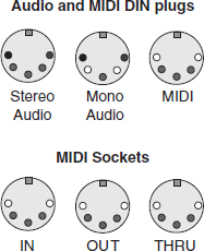
Figure A2.1 Top: Showing the difference between audio and MIDI connections (white pin indicates not used). Bottom: Standard MIDI sockets
A typical synthesizer will have three sockets as shown. The ‘IN’ will drive the synthesizer (sound making) circuits. The ‘OUT’ will carry the output of the keyboard. The MIDI system allows up to 16 instruments to be connected together in a ‘daisy-chain’ (see Figure A2.1, bottom). The ‘THRU’ socket (American spelling of 'through’) relays the data arriving at the IN socket, unchanged, onto the next instrument. In the process the electrical signal is ‘cleaned up’ and iso-lated so that a fault on one machine will not necessarily adversely affect the rest of the instruments in the chain (Figure A2.2).
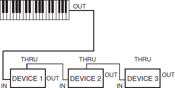
Figure A2.2 ‘Daisy-chaining’ MIDI devices
In general, each command to an instrument (Figure A2.3) takes three bytes of data to send. There is a possibility that an individual instrument may get sent too much data for it to cope with. Because of the ‘live’ nature of performance, it is vital that it can recover from this very quickly and does not ‘go out of synchronism’ with the data. This is achieved by uniquely marking the bytes of data. The first byte of a group of three is the ‘command’ byte and has three sections. The bit corresponding to the highest value represented is always ON, and this means that only numbers from 128 to 255 are sent. The 4 bits that correspond to the lowest values (0-15) are allocated to indicate which machine the command is for. Because people are not used to the concept of 'machine 0’ the channels numbers are named 1-16 although the actual numbers sent are 0-15. The remaining 3 bits are used to define the command.
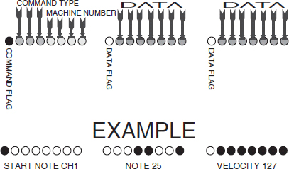
Figure A2.3 Commands to an instrument
Engineers notate the numbers represented by these 3 bits combined with the 8th bit which is always set as 8, 9, A, B, C, D, E, F (hexadecimal). The most important commands are ‘note on’ = 8, and ‘note off’ = 9.
The other two bytes are number values from 0 to 127. The 8th bit of a data byte is always 0 to indicate that the byte is data, not a command. What these data represent will depend on the command but a typical example is ‘note on’.
Here the first data byte is a number that represents the note to be played on the standard western music scale where there are 12 notes to an octave (including the black keys). Thus two note numbers that are different by 12 are an octave apart. Other commands can modify the pitch for special effects. The second data byte represents the velocity – how ‘hard’ the key is pressed.
In practice most synthesizers are polyphonic; they can sound more than one note at a time and can respond to more than one MIDI channel at a time. They may also contain drum machines, etc. with their own MIDI channel number.
Synthesizers usually send out a data ‘heartbeat’ several times a second. This can distract computers and sound cards when being switched on causing lockups or crashes. Unless you are sure that your machine is free from this problem, it makes sense to switch off or disconnect your synthesizer when you switch on your computer at the beginning of a session.