Chapter goal: While there are many filters in Photoshop, not all can be considered true warps and distorts; some are more alterations of color, as you saw in Chapter 8. This chapter, like the previous chapter, will focus on select filters that either distort or correct distortion in an image; however, this time we will explore various advanced filters.
Advanced filters are used for correcting distorts in Photoshop. These included Adaptive Wide Angle Camera Raw Filter and Lens Correction. For warping and distorting, we will look at Liquify, and in Chapter 10, we will look at the Vanishing Point filter and two of the latest Neural Filters.
You can find the projects for this chapter in the Chapter 9 folder.
Advanced Filters

A screenshot of the filter menu. The options are tiles, filter gallery, camera raw filter, lens correction, liquify, and vanishing point. On the right are the shortcuts to it.
Advanced filters in the Filter menu
Adaptive Wide Angle (Correcting Distortion of Structures)

Three illustrations of a house explain the distortion effects. From left to right, no distortion, pincushion, and barrel.
An image without distortion, pincushion distortion, and barrel distortion

A screenshot of the layers panel menu. The pathway of selecting the converting to smart object option for an image is present.
Make sure your image is converted to a smart object layer before your use the filters
Project: Straightening Room Dimensions with Adaptive Wide Angle

A photograph of the room with distortions.
A room with noticeable distortions
File ➤ Open IMG_0868_room_1_start.psd. Make an Image ➤ Duplicate for practice. In this example, I have a smart object layer and a normal background layer so that you can review certain settings and easily compare the before and after. In this case, I have turned off the visibility of the background layer so that I can easily see what alterations are happening to my smart object layer. Refer to Figure 9-3.
Besides a slight keystone distortion that affects perspective, the room is a bit tilted to one side, which we need to correct.
Now Choose Filter ➤ Adaptive Wide Angle (Alt/Option+Shift+Ctrl/CMD+A).

A screenshot of the Adaptive Wide Angle window in photoshop.
Adaptive Wide Angle filter workspace

A screenshot of the tools panel.
Adaptive Wide Angle filter tools/control and, upon mouse hover, informational help
Adaptive Wide Angle Tools (From Top to Bottom)

A screenshot of a drawing a line using the constraint tool.
Drawing a Constraint tool on the image and the selected constrain line

A photograph of the different types of drawing a line using the constraint tool control. From top to bottom, center, horizontal, and vertical.
The start of a constraint line, a horizontal constraint (yellow) and vertical constraint (magenta)

A shaded arrow and a scissor illustrated icon for the add alte
Add Alt/Option. The mouse pointer changes to an arrow and scissor if the selected constraint can be deleted, then click

Two screenshots of the drawing of a line using the constraint tool on the left. The icon of rotate and scale are on the right.
Use one of the angle guides to rotate and its end point to scale the constraint

A pop-up window titled Adaptive Wide Angle depicts a warning about a calibration failure.
Adaptive Wide Angle alert message that the constraint failed to calibrate and you need to adjust the constraint more precisely or try another constraint. Click OK
In this example, I clicked and dragged to add constraints along the wall, floor, and ceiling to the straighten lines and edges in the key parts of an image. On straight edges, I clicked and held down the Shift Key to keep the constraints vertical or horizontal while dragging and then released the mouse. Refer to Figure 9-12.

A screenshot of the room with multicolored vertical and horizontal lines on the corners and frames of the door and the window.
Adding constraints to the room

A magnified view on top of the actual zoomed photograph exhibits a brightly colored horizontal line and a marker short of touching the nearby wall.
Use the loop to view the constraint und point close up

A screenshot of the constraint-adjusted dollhouse room with its borders exhibiting noticeable curvature on top of the transparency grid.
Adjusting the constraints to straighten the room causes its border to alter and leave some gaps

A screenshot of the context menu depicts an enabled unfixed type. The other options include horizontal, vertical, and arbitrary types.
Use the pop-up menu to can set the type of constraint you want
Choose whether to straighten vertically or horizontally for a specific constraint. The color of the line of the constraint will change: Unfixed (default is cyan), Horizontal (yellow), Vertical (magenta), and Arbitrary or Fixed orientation (green).
You may need to drag out multiple constraints especially for images without a lens profile or when correcting unusual distortions. Refer to Figure 9-14.

A screenshot of the panel exhibits a highlighted polygon constraint tool icon, a tilted square with 4 vertices.
The Polygon Constraint tool can be used to square off some areas

A screenshot of a section of the ceiling of the dollhouse room atop a transparency grid with dashed lines representing invalid constraints.
Invalid constraints appear red
You can then edit a constraint by clicking the polygon constraint and dragging an endpoint. Alt/Option+Click on a selected constraint to delete or press the Backspace/Delete key.
By creating this kind of geometric constraint, you can adjust the image around part of the distorted image.

A screenshot of the slightly tilted room based on the polygon constraints.
Polygon Constraints don’t appear to correct the room’s angle

A screenshot of the panel highlights a move tool icon. On the right are images of a section of the wall of the room and a scale slider.
Use the Move tool when you want to move the image around the preview. You can also access the Hand and Zoom tools here
Hand tool (H): Drag to move the image in the window without shifting the image or constraints. Or hold down the spacebar if working with another tool. Refer to Figure 9-19.

A screenshot of zoom tool. The plus and minus buttons for zooming are present.
Lower left navigation area to zoom in or out instead of using the Zoom tool
Use Ctrl/CMD+Z when you need to undo the last step when editing a constraint.

A panel on the left of the Adaptive Wide Angle window with options such as correction and scale. The select projection model text is on the right.
Adaptive Wide Angle filter options and info as you hover over an option
OK: Commit changes and return to Photoshop.
Cancel: Close the workspace without making any changes or reset dialog while holding Alt/Option.
Correction: Select a Projection Model of either Fisheye, Perspective , Auto, or Full Spherical. Refer to Figure 9-22.

A panel on the right of the Adaptive Wide Angle window with options such as correction, scale, focal length, and crop factor. The perspective option is selected.
Adaptive Wide Angle Filter Correction Options for Perspective

A screenshot of the correction section is set to fisheye with scale, focal length, and crop factor.
Adaptive Wide Angle Filter Correction Options for Fisheye with settings and how it affects the room and constraint tools

A screenshot of the correction section set to perspective with scale, focal length, and crop factor.
Adaptive Wide Angle Filter Correction Options for Perspective with settings and how it affects the room and constraint tools
The following settings for these two corrections included Scale, Focal Length, Crop Factor, and As Shot, which I will describe shortly. Refer to Figure 9-24.

A pop-up window labeled Adaptive Wide Angle exhibits an alert with text that reads No matching lens profile found.
If your image has no lens profile or model available, you will get an alert message when you try to select the correction to Auto

A screenshot of the correction section set to auto with a scale slider set to 82%. The data for the camera and lens models used are also depicted.
Adaptive Wide Angle Filter Correction Options for Auto because you have a lens model available
For example, if you download and open an image from the iPhone 6s, you will have access to correction settings of Auto and Scale, because the lens model of the iPhone 6s back camera is 4.15 mm f/2.2. If your camera model and lens is recognized by the filter, an auto lens correction can be applied. However, you can still use Fisheye or Perspective if you need access to additional settings.
While most digital cameras will record the camera model for the image, not all smart phones or digital cameras record the lens model profiles, so in that case just use either Fisheye or Perspective options and adjust your constraints manually. In my case, Perspective worked best as an alternative.

A screenshot of the correction section with fisheye, perspective, auto, and full spherical options in the drop-down menu. A pop-up window flags the 1 to 2 aspect ratio as invalid for full spherical.
When you try to select Full Spherical, if your aspect ratio, is not correct you will see this alert message. Click OK to exit
“The aspect ratio is not 1:2, which is invalid for Full Spherical.” Click OK to exit and return to the previously selected Correction Options Example: Auto or Perspective.
In this case, your image needs to be a 360-degree panorama or image with this width and height ratio. In addition, for you to use this filter option, it will not work on a smart object layer unless it has been cropped as a normal layer first to the correct size, before converting to a smart object layer. Like Auto Correction , the image must have a lens profile. I will point out how to do that here, although it is not part of the current project.
Cropping an Image for Full Spherical

A screenhsot of the highlighted background layer with a photograph of the dollhouse room on the left side of the label.
Work on a background or normal layer when you want to alter the aspect ratio

A panel for crop tool exhibits an option to change the ratio of the photograph and straighten it among others. Below is a photograph of the dollhouse room on a 3 by 3 grid.
Use the Crop tool and its Options panel with a ratio option of 2:1 to crop to the correct size

A screenshot of a highlighted converted background copy layer above a locked background layer. Each has a photograph of the dollhouse room attached.
Convert a copy of your layer to a smart object before you enter the Adaptive Wide Angle filter again

Two screenshots of the correction sections set to auto and full spherical with both scale sliders set to 100%. Below is a photograph of the dollhouse room with intense distortions especially on the sides.
Change your Correction setting from Auto to Full Spherical
This creates a unique distortion, which may be useful for projects.
If you have created a photomerge panorama using File ➤ Automate ➤ Photomerge, the Adaptive Wide Angle filter has an additional correction option called Panorama, which is similar to Auto. After this setting is applied, it allows you to scale the image. You can also switch to Full Spherical as well as long as the panorama is cropped to the correct ratio of 2:1. For more information on how to work with Photomerge, visit https://helpx.adobe.com/photoshop/using/create-panoramic-images-photomerge.html .
When working with Panoramas manually with single layers, Edit ➤ Auto Align Layers and Edit ➤ Auto Blend Layers can also be useful commands. Go to https://helpx.adobe.com/photoshop/using/combine-images-auto-blend-layers.html .
Adaptive Wide Angle Options Continued

A screenshot of the correction section set to perspective with scale at 100%, focal length at 4.15 millimeters, and crop factor at 6.99.
Adaptive Wide Angle Settings for Correction Perspective

A screenshot of the drop-down menu from the correction section exhibits a highlighted preferences option above load constraints and save constraints.
Set your Adaptive Wide Angle preferences and load and save constraints
Unfixed Orientation (cyan), Horizontal (yellow), Vertical (magenta), Fixed Orientation (green), Invalid (red)
Mesh Color (green). The colors can be changed by clicking them and using the Color Picker.
Floating Loupe check box can be enabled for, Show/hide loupe when dragging and Loupe Size set slider: (100-300). Refer to Figure 9-34.

A pop-up window labeled Preferences exhibits constraint colors, mesh, and floating loupe sections. Each constraint type has a specific color assigned.
Set your Adaptive Wide Angle preferences for Constraint Colors, Mesh Color, and Floating Loupe options
Scale slider: Scale image after correction (50-150%). Scales the image down to see the edge of the distortion or enlarge to trim or crop. As noted, as you correct the distortion, some of the areas around the border will that have missing information due to the added constraints. This slider is the only option available for Auto, Full Spherical, and Panorama. Refer to Figure 9-35.

A photograph of the constraint-illustrated dollhouse room on a transparency grid, where unevenness is observed on the edges. The scale slider set to 87%.
Adaptive Wide Angle setting of Scale for all Correction options and how it affects the room
Focal Length slider: To specify focal length (approximately 0.39-11.59mm or higher). Pinches some areas of an image when the length is lowered or squares the image when raised. If lens information is known, this value is automatically populated. In my case, it was 4.15mm. However, I can use the slider to override manually. Note that these numbers can vary based on the type of camera used to capture the image. Refer to Figure 9-36.

A photograph of the constraint-illustrated dollhouse room on a transparency grid, where distortion of edges is observed. The options include a scale of 87%, a focal length of 1.90 millimeters, and a crop factor of 6.99.
Adaptive Wide Angle settings of Scale, Focal Length, and Crop Factor for Perspective and how it affects the room
Crop Factor slider: To specify the crop factor (0.10-10). When crop is lowered, it decreases the area to be cropped down to an elliptical area with multiple pointed edges for Fisheye and Perspective. Depending on which numbers for scale and focal length are set, crop factor is more of a bloated rounded shape. Refer to Figure 9-37.

A photograph of the circular constraint-illustrated dollhouse room on a transparency grid with a focus on an opaque window with a scale of 87%, focal length at 4.15 millimeters, and crop factor of 0.10.
Adaptive Wide Angle settings of Scale, Focal Length, and Crop Factor for Perspective and how it affects the room, causing it to appear spherical

A photograph of the constraint-illustrated dollhouse room on a transparency grid, where there was less distortion with a scale of 87%, focal length at 4.15 millimeters, and crop factor of 10.00.
Adaptive Wide Angle settings of Scale, Focal Length, and Crop Factor for Perspective and how it affects the room, causing it to appear more square
As Shot check box: When enabled, applies the focal length and crop factor from the metadata or lens profile. You will not have access to this option if there is no lens profile. Refer to Figure 9-39.

A screenshot of the correction section set to perspective with a scale of 86 %, focal length at 4.15 millimeters, and crop factor of 6.99.
Adaptive Wide Angle settings of Scale, Focal Length, Crop Factor, and As Shot, for Perspective
Detail: Preview of the loupe detail as you move your mouse about the screen. Refer to Figure 9-40.

A panel of the Adaptive Wide Angle window depicts the detail section.
Use the Detail area of the Adaptive Wide Angle workspace to see an area close up

A screenshot of the Adaptive Wide Angle window depicts the plus and minus zoom buttons.
Look in the lower left of the Adaptive Wide Angle workspace to find out the camera model and lens model
Preview checkbox: Disable to show original or enable to see the corrected Image. Refer to Figure 9-42.

A screenshot of the Adaptive Wide Angle window exhibits checked preview and show constraints checkboxes and an unchecked show mesh.
Check boxes in the lower area of the Adaptive Wide Angle filter for Preview, Show Constraints, and Show Mesh

Two photographs of the dollhouse room with and without multicolored lines representing different constraint types.
Show and hide the constraints in the preview

A screenshot of a wall of the dollhouse room, where an opaque window is observed in the center, with brightly colored folding mesh.
Show the mesh in the preview

A screenshot of the constraint-illustrated dollhouse room between a correction section set to auto with a scale of 100% and a background copy layer above smart filters and adaptive wide angle.
Using Auto Correction and Constraint tools to Straighten the room and then exiting the workspace and looking at the smart filter in the Layers panel
If you notice that there are some blank areas that are left in the image, as with the Perspective Warp tool of Chapter 7, you could try any one of the various Content-Aware options that I mentioned for filling those blank areas on a blank layer above the smart object layer. Alternatively, you could later use your Clone Stamp or Eraser tool to blend areas into the image. And you can use the Free Transform Tools from Chapter 4. See those chapter if you need more detail. Also, you can use Blend mode options for this filter.
You can review my final file, IMG_0868_room_1_final.psd.
Camera Raw Filter (Optics and Geometry)

Three logos of Photoshop, Bridge, and Camera Raw, respectively.
Both Adobe Photoshop and Bridge apps can use Camera Raw

Four screenshots of the before-and-after correction of the chromatic aberration and of the dollhouse room model with adjusted vignetting style.
The Camera Raw filter corrects chromatic aberration (upper before/after) and vignetting (lower before/after)
However, like the Adaptive Wide Angle filter, it also has distortion correcting features that you should be aware of. While the focus of this book is not color correcting, I will go into more detail about two of these workspaces tabs, Optics and Geometry, as well as some of the Tool panels. Also, while my focus is on Photoshop, I will show some basic differences to the interface in Bridge, which will appear as black rather than the gray interface in Photoshop.
Project: Working with Camera Raw to Straighten Room Dimensions

A screenshot of a highlighted background copy layer above a locked background layer. Each has a photograph of a different dollhouse room attached.
Select your smart object layer before you enter the Camera Raw filter

A screenshot of the Camera Raw window exhibits a photograph of a dollhouse room in the center.
The Camera Raw filter workspace

A photograph of a windmill with an inset of its accompanying tone curve. Below is a sentence to explain the tone curve's function in succinct detail.
Pop-up info box explaining what Tone Curve is
Also, Photoshop Camera Raw and Bridge Camera have a few key differences in their workspace, which I will point out as we take a quick tour of the workspace.

A screenshot of section of the Camera Raw workspace exhibits a two-part zoom panel, labeled Fit 39.9% within parentheses and 100%.
Camera Raw navigation area for zooming in and out of an image
On the lower right are various view settings. You can cycle between before and after views (Q) of either single view or a split of before and after, either across the top/bottom or left/right.

A screenshot of the Camera Raw workspace exhibits icons for viewing the project at any point in time such as a single view via panels and a context menu.
Camera Raw viewing options when previewing before and after work

A pop-up window labeled Preview Preferences exhibits varying numbers of checkboxes in cycle preview modes and draw items sections.
Camera Raw Preview Preferences dialog box

A screenshot of the Camera Raw workspace exhibits a histogram with 3 overlapping multicolored data. On the right is a photograph of a vertical window with red areas.
Camera Raw Histogram with warning selected for highlight areas
Click the arrow again to turn this warning off and continue to look at the lower tabs. If any camera information is preset, it will show below the histogram. Example: ISO 200, 4.2mm f/2.2 1/30s.

A panel for Edit in the Camera Raw workspace has basic, curve, detail, color mixer, color grading, optics, geometry, effects, and calibration tabs.
Camera Raw filter Edit panel and its tabs. Arrows indicate that it contains additional options
Edit Panel

A panel for Edit has color, monochrome, and browse options for the drop-down list in profile. On the right is a panel with photographs of a dollhouse room in color and monochrome in the basic tab.
Camera Raw filter Edit panel and its profile options
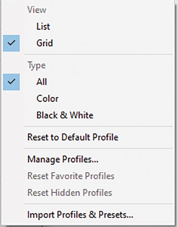
A screenshot of the context menu with a checked grid and all options under view and type above options such as reset to the default profile.
Camera Raw filter Edit panel and additional profile options
To return to the other tabs, click the back arrow on the left. Refer to Figure 9-56.
Basic Tab

A panel for the Basic tab has slider settings for temperature, tint, and so on. Below is a pop-up information box for the white balance tool.
Camera Raw filter Edit panel: Basic tab options and info box on White Balance Tool

A screenshot of the Basic tab panel presents a custom selection in the white balance drop-down list, an eye icon, and a tilted dropper icon.
The Basic tab is active with a visibility eye when a change has been made
Curve Tab

A screenshot of the Curve tab exhibits adjust options, a tone curve graph, and slider settings for highlights, lights, darks, and shadows.
Curve tab and its options
Detail Tab
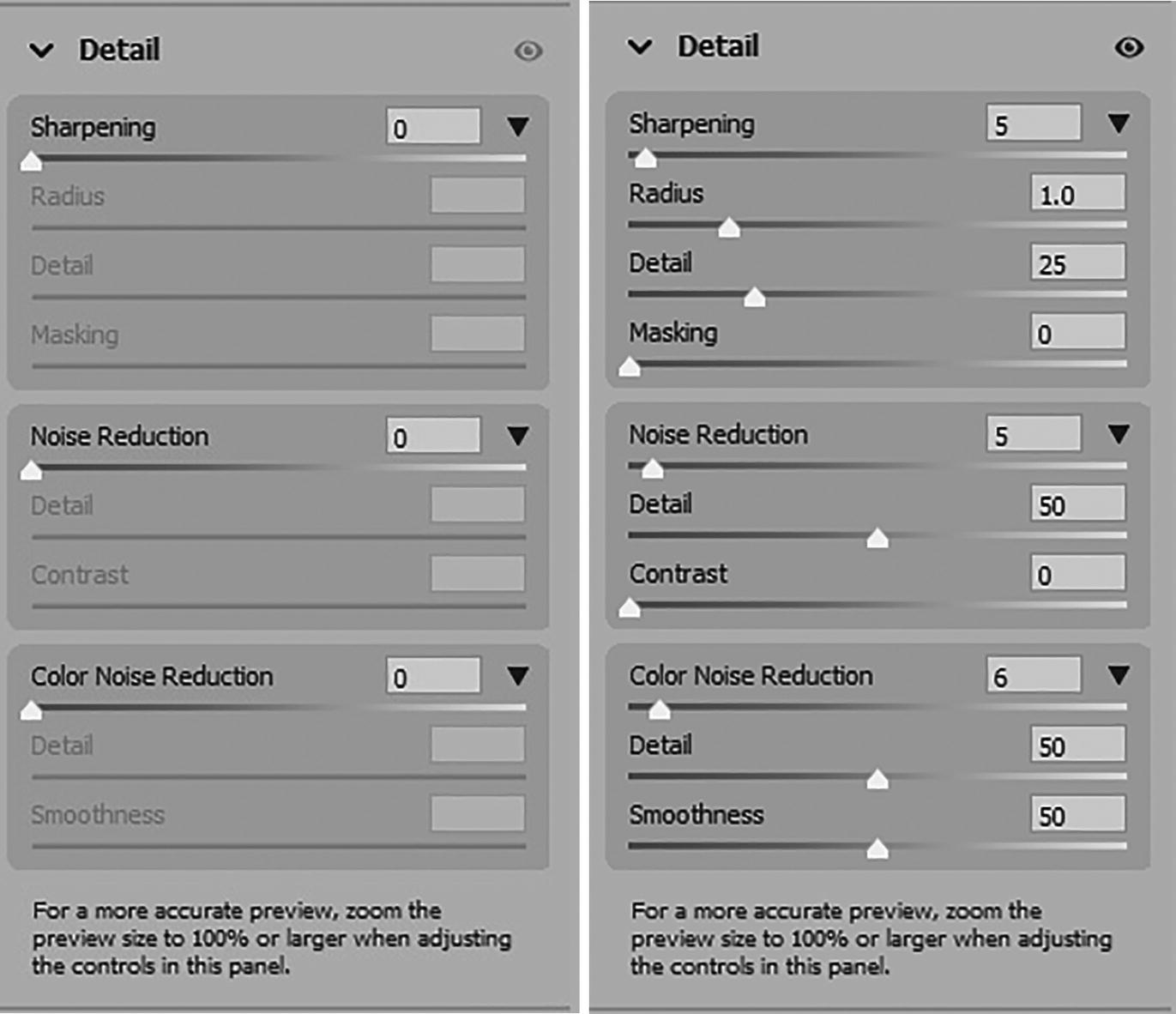
Two expanded Detail curve tabs present the change of sharpening, noise reduction, and color noise reduction values, with their sub-sliders, from 0.
Detail tab and its options with sliders altered
Color Mixer Tab

Two expanded Color Mixer tabs exhibit H S L- and Color-adjusted slider settings with tabs for hue, saturation, and luminance.
Color Mixer tab and its options and tools on the preview
This tab will change to B&W Mixer if only grayscale colors are present, or the Edit Profile of Monochrome is detected and has instead a Grayscale Mixed Targeted adjustment tool (Ctrl/CMD+Alt/Option+Shift+G).
Color Grading Tab

Two screenshots of the Color Grading tab exhibit adjust options, one circular spectrum each to calibrate mid-tones, shadows, and highlights, and various sliders for blending, balance and luminance.
Color Grading tab and its options
Optics Tab

An expanded Optics tab exhibits a distortion slider with two images of the possible outputs. Also exhibited are vignette and midpoint sliders.
Optics tab and its options and how the room alters if you move the distortion slider to the left then the right

Two photographs of a dollhouse room with distortion at 0, vignette at negative 100, midpoint at 43 and distortion at 0, vignette at + 100, and midpoint at 0 in the optics tab.
Optics tab and its options and how the room alters if you move the Vignette slider to the left, then the right, and adjust the Midpoint slider

An expanded Optics tab exhibits an opened Profile tab with options such as remove chromatic aberration. On the lower left is the Bridge logo.
Optics tab in Profile options for Bridge not available in Photoshop
I mentioned Profile and how it appears and is used in the Adaptive Wide Angle filter. However, to use these same Profile options in Photoshop, make sure you have applied your Filter ➤ Lens correction filter first to your smart object. We have not looked at that filter yet but will in the next section.

An expanded Defringe option in the Optics tab exhibits the amount and hue sliders for purple and green. A set of before-and-after corrected images is observed.
Optics tab and its Defringe options for correcting an area with chromatic aberration
These Defringe options are available in both Photoshop and Bridge.
Geometry Tab

An expanded Geometry tab exhibits 6 upright options and an expanded manual transformations option with 7 slider settings for vertical, and horizontal.
Geometry tab and its options

A screenshot of a dollhouse room with auto-corrected geometry. The icon for Auto, represented by capitalized letter A, is on the lower left.
Geometry tab Upright: Auto and how it affects the room
Level: Apply only one level of perspective correction to ensure that the image is level. This option corrects some distortion but leaves the room with a bit of keystone effects as though you are looking downwards. Refer to Figure 9-70.

A screenshot of a dollhouse room with level-corrected geometry. The icon for Level, represented by a rectangle with 2 rows, is on the lower left.
Geometry tab Upright: Level and how it affects the room
Vertical: Applies level and vertical perspective corrections. This option corrects the distortion of the room, but you still may notice a slight horizontal distortion on the floor. Refer to Figure 9-71.

A screenshot of a dollhouse room with vertical-corrected geometry. The icon for Vertical, represented by a rectangle with 3 columns, is on the lower left.
Geometry tab Upright: Vertical and how it affects the room
Full: Applies level , horizontal and vertical perspective corrections. This option is closest to Auto and stretches the image a bit more. Refer to Figure 9-72.

A screenshot of a dollhouse room with full-corrected geometry. The icon for Full, represented by 3 by 3 grid, is on the lower left.
Geometry tab Upright: Full and how it affects the room
Guided: Draws or drags out two or more guides to customize perspective corrections when this option is enabled. Refer to Figure 9-73.
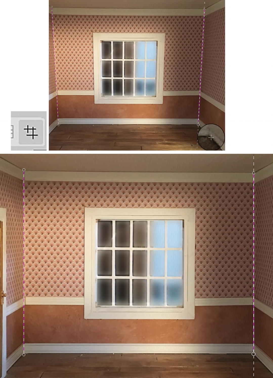
A set of before-and-after guided-corrected screenshots of a dollhouse room. The icon for Guided, represented by intersecting lines, is depicted.
Geometry tab Upright: Guided and how it affects the room when guides are added
As you draw the guides, the images adjust to the distort, similar to the Adaptive Wide Angle filter you looked at earlier.

A screenshot of a line-marked temple above a sentence to explain the use of the transform tool. On the right is an expanded Geometry tab with draw guides, loupe, and show guides enabled.
Geometry tab Transform tool info box and Draw Guides setting enabled

A screenshot of a dollhouse room with bicolored sets of vertical and horizontal lines illustrated in its corners.
Two sets of guides are added to straighten the room vertically (magenta) and horizontally (green)
Watch out, however, for invalid guide configuration. Using the Options in the Geometry tab , you can turn off and on the show guides preview or enable and use the loupe for more close-up viewing.
Press the Backspace/Delete key to delete a selected guide or click the Clear guides button to remove all the guides.
Some of the transformation sliders will reset themselves when another option is selected again from the Upright list. Refer to Figure 9-74.

An expanded Geometry tab with a message that reads for best results, apply lens corrections first. Upright options and the Manual Transformations section are depicted.
In Photoshop, the Camera Raw filter Edit panel: Geometry tab recommends you apply a lens correction first

An expanded Geometry tab exhibits 6 upright options, an unchecked constrain crop checkbox, and a Manual Transformations section. On the lower left is the Bridge logo.
In Bridge, the Geometry tab has an additional constrain crop option
In addition, if your Upright options are not accurate enough or you want to create an intentional distortion, you can set Manual Transformations using the sliders for correcting Vertical (-100, 0, +100), Horizontal (-100, 0, +100) to correct key stoning, Rotate(-10, 0, +10), Aspect (-100, 0, +100) similar to wide angle lens, Scale (50-150), Offset X(-100, 0, +100) and Offset Y (-100, 0, +100). Refer to Figure 9-78.

A photograph of a dollhouse room with changes based on vertical at negative 2, horizontal at + 27, rotate at negative 3.0, aspect at negative 12, the scale of 75, offset x at negative 8.4 and offset y at + 6.5 from the Manual Transformations section.
Geometry tab Manual Transformations option sliders
As you drag the slider, the grid appears in the preview and displays the changes.
Effects Tab

Two screenshots of Effects tabs exhibit the change of grain and vignetting values, along with their sub-sliders and a drop-down menu, from 0.
Effects tab and its options for Grain and Vignetting
Calibration Tab

An expanded Calibration tab has a dropdown process menu, a tint slider for shadows, and hue and saturation sliders for red, green, and blue primaries.
Calibration tab and its options
Other Camera Raw Tool Panels for Photoshop and Bridge
Lastly, I will just point out the basic tools in this area, running down the far-right side. Note that if you want to toggle to Full Screen mode while working, press this button or the (F) key.

A 2-section side panel exhibits six icons for different tools. A meatball menu is located at the bottom.
Additional panels and options
Crop and Rotate Tool (C)

A dropdown menu for aspect ratio, angle slider, and constrain to image checkbox under crop and 4 options under rotate and flip. The Bridge logo and crop icon are on the lower left.
Bridge Camera Raw filter Crop panel: Crop and Rotate & Flip options
Healing (B)

A screenshot of a marked pyramid at the Louvre above a text box for spot removal. The right box shows heal options like type, size, feather, opacity and visualisation spots.
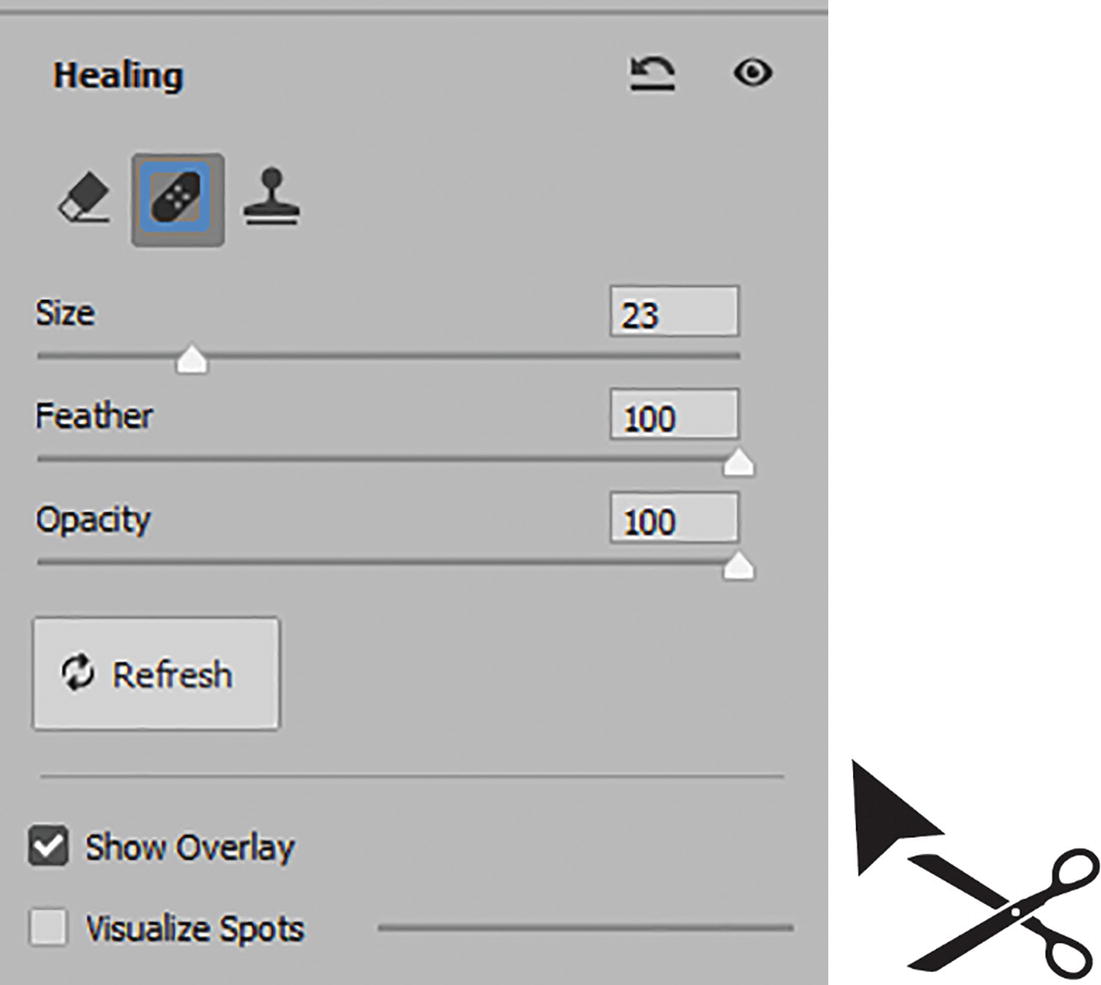
Camera Raw Filter Healing Panel: with an Info Box on how to use the Content-Aware remove, heal and clone options

A screenshot of the Heal panel has a dropdown menu for type, highlighting the heal option above the clone option.
Camera Raw Filter Healing Panel: Options
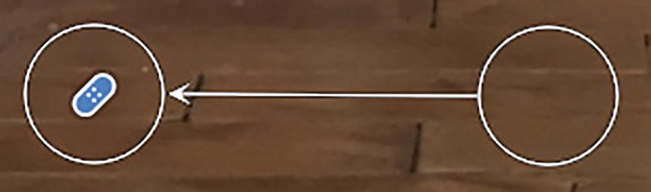
For example, with the Clone option (Figure 9-84), you can then choose a clone location for your brush that you can drag and move around after you paint. You can alter the size, feather, and opacity of your clone stamp. Or press the / key on your keyboard or Refresh button to update and sample a new area or spot with different content.

A screenshot of a dollhouse room exhibiting its wooden floor with two bicoloured dashed circles connected by a dashed line.
Camera Raw Filter Healing Panel: using brush setting to clone on the preview

A panel exhibits a highlighted background copy layer above smart filters, which include the camera raw filter.
This heal or clone does not appear on the smart filter mask; it’s only within the Camera Raw filter, so you can edit it only within the smart filter
A panel for Heal has a dropdown menu, 3 slider settings, and 2 checkboxes. On the lower right is an illustration of an angled arrowhead on the upper left of rightward scissors.
Camera Raw Filter Healing Panel: with its options for the brush and you can use the Alt/Option key to change the mouse pointer to an arrow and scissor to click on a selected heal in the preview to delete it
Or to remove all selections, click the reset heal button in the upper right next to the Visibility eye. (Figure 9-87).
A screenshot of a dollhouse room exhibiting its wooden floor with 2 connected bicoloured circular spots as sample and selection areas.
Click to add a heal to the preview area

Two screenshots of a dollhouse room with capsule-shaped markings on a section of its wooden floor for healed and cloned areas.
Hold down the shift key as you drag to heal or clone a larger area
Content-Aware Remove eraser is a new feature that will allow you to adjust the size and opacity of the brush head. Ctrl/CMD+drag on photo to select a custom source for removal of blemishes or unwanted items in an image. Refer to link for more details:
https://helpx.adobe.com/camera-raw/using/whats-new/2023.html#content-aware-remove

A screenshot of Heal panel exhibits a maxed slider for a checked visualize spots checkbox and a checked overlay checkbox. On its right is the resulting monochromatic image of a window in the dollhouse room.
Camera Raw Filter Healing Panel: options for Content Aware remove and visualize spots and overlay and how to visualize spots previews

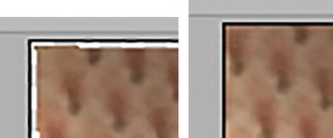
2 screenshots of a wall in the dollhouse room with and without a vertically oriented pair of capsule-shaped overlay boundaries on each side of a window.
Show Overlay Preview on and off of a heal
The Healing tool samples will update with the Geometry Tab if altered.
Masking Tool (M)

A panel has subject and sky selections under create new mask option. Below are options like brush, linear gradient, radial gradient, colour range and luminance range. On the lower left is a dashed circle as its icon.
Camera Raw Filter Masking Tool Panel: and its options
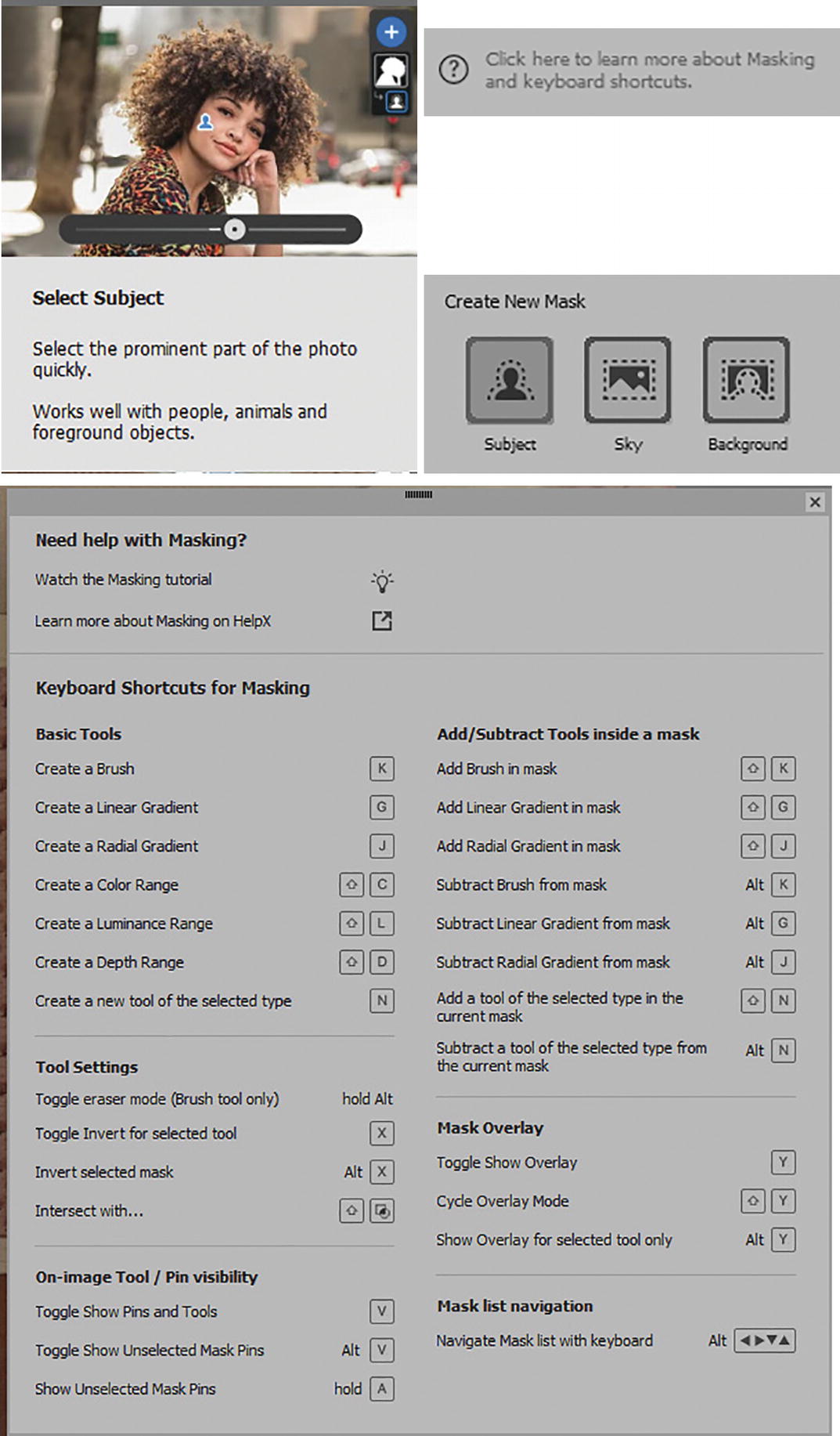
A pop-up menu for the subject selection with a picture of a woman. Below is a window with 5 sections of keyboard shortcuts related to the masking tool.
Camera Raw Filter Masking Tool Panel has info boxes as well as masking helps with key commands

A panel has various tabs such as light and colour under the radial gradient mask. An image of it in action and a context menu with a highlighted select subject option are depicted.
Camera Raw Filter Masking Tool Panel: when a mask type is chosen more options are then available to edit the mask

A context menu exhibits options such as rename, intersect mask with, and delete all masks. Below is a highlighted Select Subject option with floating text on inverting the selected area of the mask component.
Camera Raw Filter Masking Tool Panel: when a mask type is added and chosen more options are then available to edit the mask including inverting the mask
Once a mask is created it can be inverted, you can add or subtract from the mask using the same selection options as well as intersect with other masks.
Each new mask you create comes with sub-tool options that offer a variety of settings so you can adjust the new mask selection and then use sliders for color correction for that selected area such as light, color, curve, effects, and details. Refer to Figure 9-94 and Figure 9-95.
This mask does not appear on the Smart Filter once applied as it is a selection only applied within Camera Raw. For more details and instructions on this updated area, visit: https://helpx.adobe.com/camera-raw/using/masking.html .
Some Mask features, like depth range, may not be available if you do not have supported lens profiles for your images. Refer to Figure 9-92.
Red Eye (Shift-E)

Two screenshots depict sliders and checkboxes for red eye. Below is a section with dropdown menus for pupil size and darkening amount.
Camera Raw Filter Red Eye Panel: you can use this panel to alter red eye or pet eye and is more advanced than the Red Eye Tool in the Photoshop Tools panel

Two sets of before-and-after eye-color-adjustment photographs of the eyes of different cats.
Cat’s or pet’s eyes in gold and red before and after using the Camera Raw Red Eye panel and then adjusting the selections
Snapshots (Shift+S)

A pop-up menu for snapshots has a text box below a set of photographs of a flowering plant. Its dedicated panel, logo as a stack of rectangles, and the Bridge logo are depicted.
The Camera Raw filter Snapshots panel is only available in Bridge, not Photoshop
Presets (Shift-P):

A panel for Presets has a slider and 5 portrait tabs and its logo is a tilted Venn diagram is depicted.
Camera Raw filter Presets panel and more image settings
The ellipse area allows for additional image setting options of loading and saving settings as .xmp files. Refer to Figure 9-99.
Additional tools in the lower right are
Zoom tool (Z): Use to zoom in or out and double-click to fit in view. Refer to Figure 9-100.

A 2-section side panel exhibits 4 icons of camera raw filter tools. A highlighted magnifying glass, raised hand, tilted dropper, and 3 by 3 grid are listed.
Camera Raw filter tools
Hand tool (H): To move around a close-up of the images without moving geometry guides by mistake. Use the Spacebar key if you are using other tools. Refer to Figure 9-100.
Toggler Sampler Overlay (S): Color sampler settings. Options appear in the area above the preview area. Refer to Figure 9-100 and Figure 9-101.

A panel titled Color Sampler has its icon, a tilted dropper, as the assigned button for creating a new sample.
Camera Raw filter options for the Toggler Sampler Overlay tool

A panel for toggle grid overlay has grid size and opacity sliders. Below is a section of the photograph of a dollhouse room with line patterns on the windowpanes.
Camera Raw filter options for the Toggle Grid Overlay
Bridge also allows for you to view multiple images at one time as a film strip, in the lower areas below the Preview. However, this option is not available in Photoshop since we are working with single layers.

Two images of a section of a panel with one capsule-shaped O K button each and Reset and Cancel labels on the side, respectively.
Hold down the Alt/Option key when you want to reset all changes and click the button
Click OK to confirm your settings or Cancel and then, if you have made changes, click Yes to dismiss the changes in order to exit the workspace without saving your changes.

A pop-up window labeled Camera Raw has a question that reads Cancel all changes and dismiss Camera Raw. Yes and No buttons are on the lower right.
Camera Raw alert message if you click the Cancel button and don’t commit your changes. Click Yes to exit

An icon for a Bridge and an illustration of a downward arrow into a square icon.
Bridge icon and its Convert and Save button
For additional information on color correction in Camera Raw, visit these links: https://helpx.adobe.com/camera-raw/using/introduction-camera-raw.html and https://helpx.adobe.com/camera-raw/using/whats-new.html .

A panel exhibits a highlighted background copy layer above smart filters, which include the camera raw filter. All items are observed to be visible.
Double-click to enter the Camera Raw filter any time to make changes
Like Adaptive Wide Angle, you can also access blending modes for the layer by double-clicking the icon beside the filter name.
Lens Correction

A panel highlights the background copy layer above smart filters, which include the camera raw filter. All are visible except for the last item.
Use your smart object layer if you want to add Lens Correction while the Camera Raw filter visibility is hidden
While the smart object layer is selected, go to Filter ➤ Lens Correction (Shift+Ctrl/CMD+R).

A window labeled Lens Correction exhibits a photograph of a dollhouse room in the center with various options depicted in the surrounding panels.
Lens Correction filter workspace

A side panel exhibits five icons for different tools. A floating text box contains a message that reads Place mouse over control for help.
Lens Correction filter tools and help when you hover over them with the mouse
Lens Correction Tools
Remove Distortion tool (D): Drag outwards from or inwards to the center to correct distortion. This will cause the image to bulge or pinch. Refer to Figure 9-110.

Two screenshots of a wall of a dollhouse room with distortions based on the remove distortion tool. Its icon is depicted on the lower left.
Remove Distortion tool and how it affects the appearance of the room

A screenshot of the two buttons such as O K and Reset.
Hold down the Alt/Option key when you want to access the Reset button

A screenshot of the navigation area includes zoom buttons, camera model, lens model, and camera settings data, preview and show grid checkboxes, color, and dropdown menu for size.
Lens Correction filter lower navigation area with camera info, preview, and grid options
Straighten Tool (A): Draw a line to straighten the image to a new horizontal or vertical access. Refer to Figure 9-113.

An icon for the straighten tool as a horizontally oriented object underneath curved dash line.
Straighten tool and how it affects the appearance of the room
Move Grid tool (M): Drag to move the alignment grid. The grid adjustment can be found on the lower area of the workspace next to the camera profile info and Preview check box. Use Show Grid to show the grid when enabled and adjust the color using the Color Picker and adjust the Grid Size (8-256). Refer to Figure 9-114.

A screenshot of a dollhouse room with grid lines and the move grid tool icon on the lower left. Below are data and various options from the bottom panel.
Move Grid tool and how it affects the appearance of the room and grid options in the lower area of the Lens Correction workspace
Hand Tool (H): Drag or move the image in the window when zoomed in to an area. Or hold down the spacebar key if working with another tool. Refer to Figure 9-11.

A side panel exhibits a stack of a highlighted raised hand icon for the hand tool and a magnifying glass for the zoom tool.
Hand and Zoom tools
In my case, I did not use any of the tools; however, I am going to make sure that I have the correct settings in the Auto Correction tab.
Auto Correction Tab

A panel with auto correction tab with a checked geometric distortion under correction, checked auto scale image, and transparency-set edge.
Lens Correction filter Auto Correction tab and its options
Geometric Distortion check box: Enables automatic geometric distortion correction. I have this enabled.
Chromatic Aberration check box: Enables automatic chromatic aberration correction. In this case, there was none and it is disabled, but you can reset this in the Camera Raw filter manually if required.
Vignette check box: Enables automatic vignette correction. In this case, there was none and it is disabled, but you can reset this in the Camera Raw filter manually if required.
Auto Scale Image check box: Enables automatic scaling when correcting distortions and unintentional scale while adjusting perspective and angle. This crops the transparent gap edge when enabled. Refer to Figure 9-116 and Figure 9-117.
A set of before-and-after auto-scaled photographs of a section of a patterned wall of a dollhouse. No empty space is observed in the latter.
Auto Correction tab, Auto Scale Image option when disabled and enabled for image
Edge: Specifies edge treatment for correction images. From the dropdown menu, choose one of the options: Edge extension, Transparency, Black Color, White Color. This is apparent only when the Auto Scale Image check box is disabled. Refer to Figure 9-118.
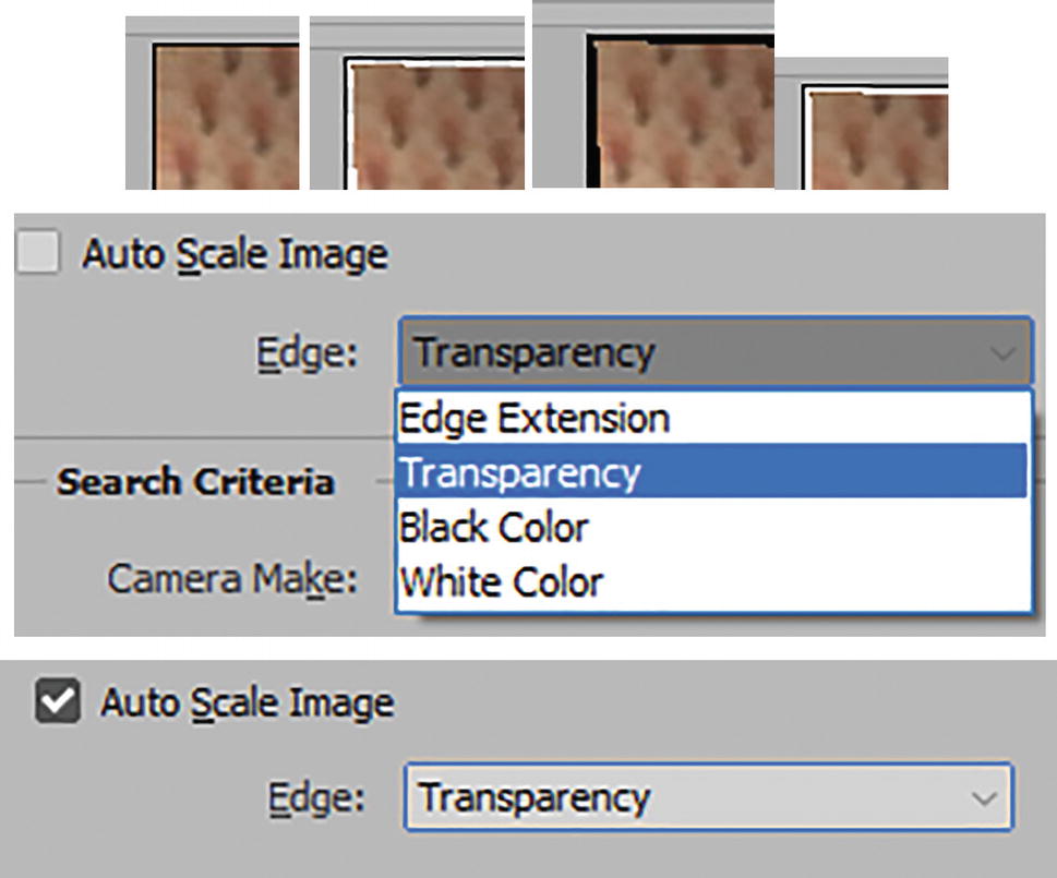
4 photographs of a section of a patterned wall of a dollhouse room as outputs from the edge extension. Below is a checked auto-scale image with an edge set to transparency.
Auto Scale Image option disabled and then edge options from dropdown menu as they appear in the image, and then Auto Scale image enabled to crop edge
Search Criteria Menu: When set to Match Image Sensor Size or Prefer Raw Profiles, this can alter how the distortion is corrected. In my case, I set it to Match Image Sensor Size and because my image had a profile, the Camera Make filled itself in automatically. See the camera model profile on the lower left of the workspace. Refer to Figure 9-119.

A section of a panel in the Lens Correction window exhibits search criteria with dropdown menus.
Lens Correction filter Search Criteria and menu options

A drop down menu for search criteria exhibits options such as choosing a camera model, all, and various iPhone models. The iPhone 6 s option is highlighted.
Search criteria for camera model

A panel for search criteria has the camera model set to iPhone 6 s and the lens model set to all. Below is a list of related lens models under Lens Profiles and a context menu with Show in Explorer and Browse Adobe Lens Profile Creator Online options.
Searching for camera model, lens model, and lens profile
Lens Profiles: You can view optional lens profiles under this menu such as Show in Explorer (to see the lens profiles in the Explorer window on your computer) or Browse Adobe Lens Profile Creator Online to see addition lens profile options if available. Refer to Figure 9-121.
If you cannot access Adobe Lens Profile Creator, refer to this link: https://helpx.adobe.com/camera-raw/digital-negative.html#Adobe_Lens_Profile_Creator .
Custom Tab

A panel with a custom tab, and dropdown menu for settings set to default correction. Below is a value of 0.0 to remove distortion in the geometric distortion section.
Lens Correction filter Custom tab and its options
Settings: Use Lens Default , Previous Correction (Last used setting), Custom, Default Correction, or saved settings. From the Settings menu to the right you can Load, Save, Delete settings, Set Lens Default, and Delete Lens Default. These settings are in an .lcs file format. Refer to Figure 9-123.

A dropdown menu for settings in the custom tab highlights the default correction option below 3 others. On the right is a 2-part menu with various options.
Lens Correction filter Custom tab and its options for settings
Geometric Distortion: Remove distortion slider: Move left to fix a pincushion distortion (-100 to 0) or right to fix a barrel distortion (0 to +100). Refer to Figure 9-124.

A panel of the custom tab with a geometric distortion section below the settings. It has a set value for removing distortions and a slider for 2 extreme distortions.
Lens Correction filter Custom tab and its options for correcting geometric distortion
Chromatic Aberration: Fix Red/Cyan Fringe slider, Fix Green/Magenta Fringe slider, and Fix Blue/Yellow Fringe slider. Use the sliders to correct specific color fringes around edge details within the image. The default for each slider is 0 but you can move the sliders left (-100) or right (+100). Use your Zoom tool to make sure the changes are occurring. Refer to Figure 9-125.

A chromatic aberration section in the custom tab exhibits fix red slash cyan, fix green slash magenta, and fix blue slash yellow fringe sliders.
Custom tab and its options for correcting chromatic aberrations
Vignette: Amount (darken, lighten from -100, 0, +100) adjusts the vignette’s under- or over- exposure around the edges of the image. Midpoint modifies the midpoint to affect the spread and restriction of the vignette correction (0 to +100). Alternatively, you can use the vignette sliders to create an artistic effect if you are trying to give your image a vintage look. Refer to Figure 9-126.

A vignette section in the custom tab exhibits an amount slider set to 0 between darken and lighten and a midpoint slider set to + 50.
Lens Correction filter Custom tab and its options for correcting a vignette
Transform: Vertical Perspective modifies the vertical perspective at the top or bottom of the image to make the image’s vertical lines parallel (-100, 0, +100).
Horizontal Perspective modifies the horizontal perspective at the left or right side of the image to make the horizontal lines parallel (-100, 0, +100).
Angle set the angle of rotation for the image and you can use the Straighten tool to set this to 0-360° or alter with the dial or enter in the text box.
Scale scales the image after correction (50-150%). This does not affect the document size, but rather crops the image to avoid blank areas while you are altering other options. Refer to Figure 9-127.
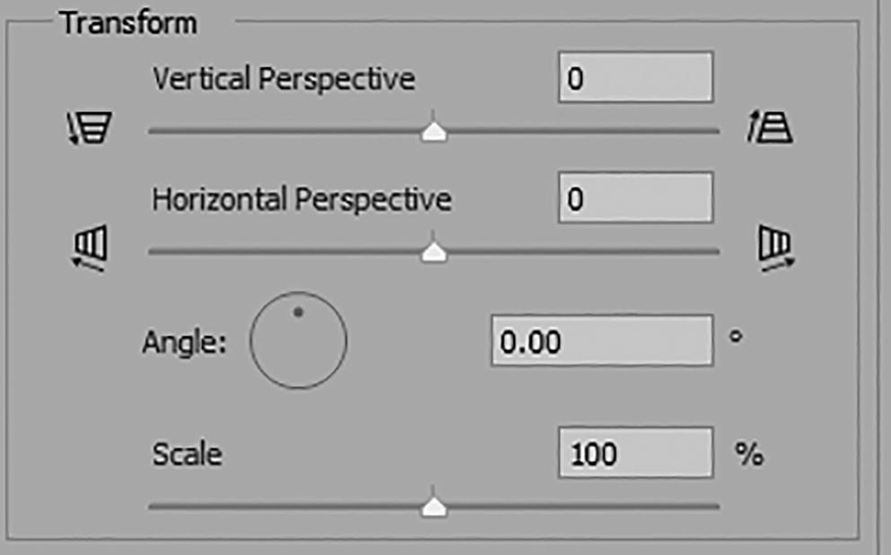
A transform section in the custom tab exhibits sliders for scale and vertical and horizontal perspectives. An angle of rotation tool is also depicted.
Lens Correction filter Custom tab and its options for making image transformations
You may need to return to your auto correction tab and adjust further to correct settings.
In this case, I left the settings in the Custom area at default. But for your project, you may want to alter the sliders.
Use the File ➤ Automate ➤ Lens Correction dialog box when you have multiple photos in a batch that need lens correction.

A screenshot of the O K and Cancel buttons.
Click OK to commit your Lens Correction settings

Two similar panels exhibit a background copy layer above smart filters, which include lens correction above invisible and visible camera raw filters.
Turn the Camera Raw filter visibility back on to compare your work so far

A screenshot of a dollhouse room on a transparency grid post-filter application. The image resembles the shape of a trapezoid within a rectangle.
The room is now straighter with both filters applied to the smart object layer
You can look at my file IMG_0886_room_2_final.psd to review settings that I used to straighten the room and double-click either the smart object filters, Lens Correction filter, or Camera Raw filter.
Likewise, as mentioned with the Adaptive Wide Angle Lens , if there is any stretching or distortion or gaps after you have applied your Camera Raw filter and Lens Correction filter, you can always add back to image’s blank areas on a new layer, as you did with the Perspective Warp tool of Chapter 7. You could try any one of the various Content-Aware options that I mentioned in that chapter. Later, you can fill in the blanks using the Clone Stamp and Eraser tools to blend areas in the distorted image.
For additional lens and noise reduction options , you can visit https://helpx.adobe.com/photoshop/using/correcting-image-distortion-noise.html .
Liquify Filter
If you want to really warp and distort part of an image like the Smudge tool in Chapter 2 or the Puppet Warp tool in Chapter 6, then the Liquify filter might be just what you are looking for. It also might be considered a correction tool, depending on your project. While this tool is generally associated with the other touch-up tools for doing cosmetic adjustments on models, there is no reason why you cannot use it on other types of photographs as well or even on images of your pets. As you saw earlier with other advanced filters, for your projects, working with a smart object layer so that you can return and edit any time by double-clicking the smart filter name, is the best solution.
Project: Liquify (Minerals)
In this first example, we will start practicing with the Liquify filter on a copper rock and a piece of shiny metal copper. I want to see the copper pool and flow over the rock so I think this filter will give me at least the starting point for that effect.

A photograph of melting copper on a similar rock against a stone backdrop.
Copper rock samples on a stone background

A window labeled Liquify has a photograph of melting copper on a similar rock in the center with various options depicted in the surrounding panels.
The Liquify Filter workspace

A 5-section side panel in the Liquify window exhibits a total of 12 icons for different tools such as the highlighted bloat tool.
Liquify Filter tools
Liquify Tools
Forward Warp Tool (W): Similar to a Brush or Smudge tool , drag with the tool left, right, up, or down to create a warp-like smudge based on the drag direction. See Brush tool options in the Properties panel on the right for tool options. Refer to Figure 9-134.

A panel of the properties of the forward warp tool exhibits sliders of size at 609, pressure at 50, density at 50, and the rate at 0 along with an unchecked stylus pressure checkbox and a checked pin edges checkbox.
Forward Warp tool and its Brush Tool Options properties
You can adjust the brush’s Circumference Size (1-15000, for size of selected brush currently in use), the Density Brush edge strength (0-100, used for feathering), the Pressure distortion strength (1-100, used as you drag the brush), Rate for stationary brush (0-100, controls flow rate when mouse button is held down in one location and is disabled for this brush and for other stationary brushes), Stylus pressure (if available when using a stylus, is affected by the brush pressure), Pin edges check box (to lock image’s edges and prevent missing information in the corners when the brush is passed over). Refer to Figure 9-134.
Like other mentioned Brush tools, you can Click and then Shift+Click to move in a straight line. Use the left ([) and right (]) bracket keys on the keyboard to decrease or increase the brush size quickly. The smaller the brush, the less noticeable the distortion.

A photograph of liquified copper spreading to the edges of the rock beneath it. This is an output from the slider values in the forward warp tool.
Liquify Filter with Forward Warp tool applied to the copper melt ends
Reconstruct tool (R): Acts much like an eraser or History Brush tool, as seen in Chapter 2. It restores areas altered by the Forward Warp tool or other brush tools, which we will look at next.
Like the Forward Warp tool, you can find additional settings in the Properties Brush Tool Options and the rate setting is available. Use your left and right bracket keys to decrease or increase the brush size quickly. Refer to Figure 9-136.

A panel of the properties of the reconstruct tool exhibits sliders of size at 100, pressure at 100, density at 50, and the rate at 80 along with an unchecked stylus pressure checkbox and a checked pin edges checkbox.
Reconstruct tool and its Brush Tool Options properties
Click and then Shift +Click to move in a straight line. Add the Alt/Option key while dragging to turn it into the Smooth tool instead.
Further options for this brush can be found in the lower area of the Properties panel; see the section on brush reconstruct options later in this section.

A photograph of a more refined melting of copper on the rock beneath it. This serves as the output from the slider values in the reconstruct tool.
Reconstruct Tool applied to copper melt ends
Smooth tool (E): Like the Reconstruct tool, it can be used to smooth out the ripple areas altered by the Forward Warp tool or other brush tools, which we will look at next. Like the Forward Warp tool, you can find additional settings in the Properties Brush Tool Options and the rate setting is available. Refer to Figure 9-138.

A panel of the properties of the smooth tool exhibits sliders of size at 100, pressure at 100, density at 50, and the rate at 80 along with an unchecked stylus pressure checkbox and a checked pin edges checkbox.
Smooth tool and its Brush Tool Options properties
Use your left and right bracket keys to decrease or increase the brush size quickly.

A set of before-and-after photographs of the protruding melt pool on the left side of the liquified copper in relation to the use of the smooth tool.
Smooth tool applied to edge of copper melt before and after
Twirl Clockwise tool (C): Gradually, with your set brush size , twirl in an area clockwise. The longer you hold down the mouse, the more that area will bend and twirl. Like the Forward Warp tool, you can find additional settings in the Properties Brush Tool Options. Refer to Figure 9-140.

A panel of the properties of the twirl clockwise tool exhibits sliders of size at 418, pressure at 100, density at 50, and the rate at 80 along with an unchecked stylus pressure checkbox and a checked pin edges checkbox.
Twirl Clockwise tool and its Brush Tool Options properties
If you want to twirl counterclockwise, add the Alt/Option key as you hold the mouse down. Add the Shift key for a more aggressive clockwise twirl or Alt/Option+Shift for the aggressive twirl to be counterclockwise.
Use your left and right bracket keys to decrease or increase the brush size quickly.
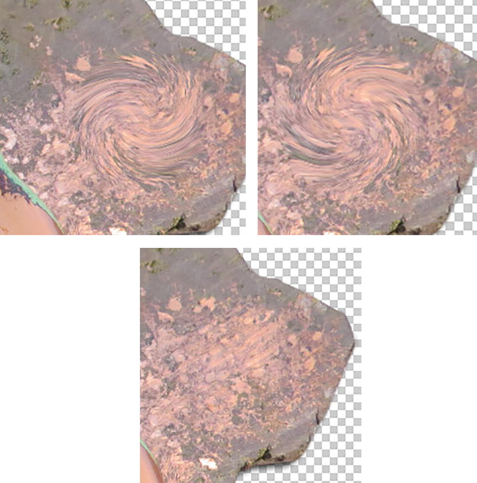
Three photographs of the resulting scattering of melted copper post-application of various tools such as twirl clockwise and reconstruct.
Twirl Clockwise tool applied, then Alt/Option key added, and then the Reconstruct tool used to erase the twirl
Pucker tool (S): Creates an area of pucker based on your brush size , gradually pulling the area inside the brush inward the longer you hold the mouse down. Like the Forward Warp tool, you can find additional settings in the Properties Brush Tool Options; however, the Pressure setting is not available. Refer to Figure 9-142.

A panel of the properties of the pucker tool exhibits sliders of size at 100, pressure at 1, density at 50, and the rate at 80 along with an unchecked stylus pressure checkbox and a checked pin edges checkbox.
Pucker tool and its Brush Tool Options properties
Adding the Alt/Option key causes the tool to change to the Bloat tool. Add the Shift key for a more aggressive pucker or Alt/Option+Shift for a more aggressive bloat. Like other brushes, you can Click and then Shift+Click or Alt/Option+Shift+Click if you want the pucker or bloat to follow a straight line. Use your left and right bracket keys to decrease or increase the brush size quickly.
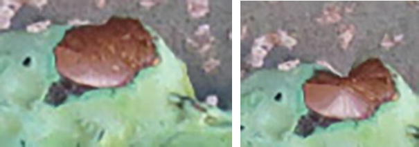
A set of before-and-after photographs of a drop of copper in relation to the use of the pucker tool. It leads to a shaved spot at the top of the drop.
Pucker applied to one of the copper spots before and after
Bloat tool (B): Creates an area of bloat based on your brush size , gradually pushing the area inside the brush outward the longer you hold the mouse down. Like the Forward Warp tool, you can find additional settings in the Properties Brush Tool Options; however, the Pressure setting is not available. Refer to Figure 9-144.

A panel of the properties of the bloat tool exhibits sliders of size at 150, pressure at 1, density at 50, and the rate at 80 along with an unchecked stylus pressure checkbox and a checked pin edges checkbox.
Bloat tool and its Brush Tool Options properties
Adding the Alt/Option key causes the tool to change to the Pucker tool. Add the Shift key for a more aggressive bloat or Alt/Option+Shift for a more aggressive pucker. Like other brushes, you can Click and then Shift+Click or Alt/Option+Shift+Click if you want the bloat or pucker to follow a straight line. Use your left and right bracket keys to decrease or increase the brush size quickly.

A photograph of an ovoid-shaped drop of copper before using the bloat tool. The next photograph exhibits the notable expansion of the subject.
Bloat applied to one of the copper spots before and after
Push Left tool (O): like the Forward Warp tool, it pushes the pixels in the brush left or right by dragging and moving the brush up or down, depending on how you drag over the image. As with the Forward Warp tool, you can find additional settings in the Properties Brush Tool Options; however, the Rate setting is not available. Refer to Figure 9-146.

A panel of the properties of the push left tool exhibits sliders of size at 100, pressure at 100, density at 50, and the rate at 0 along with an unchecked stylus pressure checkbox and a checked pin edges checkbox.
Push Left tool and its Brush Tool Options properties
Adding the Alt/Option key causes the tool to change to the Push Right tool, while dragging and moving up or down and shifting the pixels. Add the Shift key for a more aggressive left push or Alt/Option+Shift for a more aggressive right push. Like other brushes, you can Click and then Shift+Click or Alt/Option+Shift+Click if you want the push to follow a straight line. Use your left and right bracket keys to decrease or increase the brush size quickly.

A photograph of the protruding melt pool on the left side of the liquified copper. Using the push-left tool results in changes in the melt flow as observed in the next photograph.
Push Left tool used to smooth out the melt and modify it
Freeze Mask tool (F): Use this tool to prevent areas from being affected by the other brush liquify tools while you create distorts. This includes the Reconstruct tool. Like the Forward Warp tool, you can find additional settings in the Properties Brush Tool Options; however, the Rate setting is not available. Refer to Figure 9-148.

A panel of the properties of the freeze mask tool exhibits sliders of size at 100, pressure at 100, density at 50, and the rate at 0 along with an unchecked stylus pressure checkbox and a checked pin edges checkbox.
Freeze Mask tool and its Brush Tool Options properties
It paints a red mask, depending on your brush size. We’ll look at the mask option and details in the Properties panel later in this section. Now, if you paint in those areas with another tool, they will not be affected by the warp because that area is locked or frozen as it would be if you were using a mask or selection. Refer to Figure 9-149.
As you paint, you can add the Alt/Option key and it will switch to the Thaw Mask tool, allowing you to erase the Freeze Mask.
Like other brushes, you can Click and then Shift+Click or Alt/Option+Shift+Click if you want the Freeze Mask tool or Thaw to follow a straight line.
Use your left and right bracket keys to decrease or increase the brush size quickly .

A photograph of the copper rock with red-marked edges. The protruding melt pools on the left and right sides are exempt from the barrier.
Freeze Mask painted around the edge of the copper rock to prevent distortion from other tools
Thaw Mask tool (D): Use this tool when you want to erase the red mask that you created with the Freeze Mask tool and to restore areas affected by the other brush liquify tools while you create distorts. We’ll look at the mask options and details in the Properties panel later in this section. As with the Forward Warp tool, you can find additional settings in the Properties Brush Tool Options; however, the Rate setting is not available. Refer to Figure 9-150.

A panel of the properties of the thaw mask tool exhibits sliders of size at 100, pressure at 100, density at 50, and the rate at 0 along with an unchecked stylus pressure checkbox and a checked pin edges checkbox.
Thaw Mask tool and its Brush Tool Options properties
As you paint, you can add the Alt/Option key and it will switch to the Freeze Mask tool, allowing you to add a Freeze mask. Like other brushes, you can Click and then Shift+Click or Alt/Option+Shift+Click if you want the Thaw Mask tool or Freeze to follow a straight line. Use your left [ and right ] bracket keys to decrease or increase the brush size quickly.

A photograph of the copper rock with the melting of a similar element on top of it.
Use the Thaw Mask tool to erase the Freeze Mask tool
Face tool (A): If you are working with human faces , this tool may be helpful to you. However, pet faces may not be detected, and as this copper stone example contains no faces, you will get a warning message when you click on this button. Click OK and click on another tool to exit. Refer to Figure 9-152.

A pop-up window labeled Liquify has a message that reads No faces are detected in this image. On the lower left is a faceless icon for the face tool.
Face tool will not operate and will show an info message if no face is present. Click OK
Hand Tool (H): Move around the image while zoomed in or hold down the spacebar if working with another tool. Refer to Figure 9-153
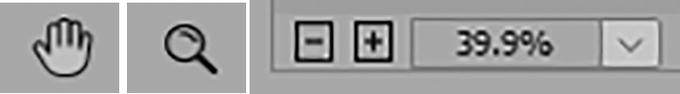
A set of icons for the hand and zoom tools. On the right is a percentage of 39.9 for the zoomed image.
Liquify filter Hand tool, Zoom tool, and zoom in and zoom out navigation
Zoom Tool (Z): Zoom in or Alt/Option zoom to zoom out, or use the navigation buttons, or use the dropdown menu in the lower left.
For additional reconstruct settings, refer to the Properties Panel Brush reconstruct options mentioned at the end of the section on the Liquify filter.

A photograph of melting copper on a copper rock post-filter application. Below is a pop-up window for previewing and highlighted copper rock layer above smart filters, which include liquify, in the Layers panel.
When finished with your Liquify filter, click OK to exit and view the smart object filter in the Layers panel

A panel for the Tools section of the eraser tool exhibits various sliders and brush styles. The tool's icon and filled smart filters in the Layers panel are depicted.
Use your Eraser tool brush options and Tools panel default colors to paint on the smart filter layer to clean up edges

Two photographs of the left and right protruding melt pools of copper with corrected edges via the eraser tool.
Erasing on the smart filter restored some edges around the rock where the copper melts over
You should usually edit the mask as a last step, because if you decided to make further modifications at this point to the warp or liquify after exiting the Liquify filter, the mask will not update and so you will need to manually modify the smart filters mask. Refer to Figure 9-155.
Afterwards I added blank layers for additional blends and shadows to make the melt look more realistic. Using a layer blending mode like Overlay, and painting with a white brush in a new layer and lowering the opacity to 67%, can add back some highlights on the Copper Blend layer. The Shadow layer was painted with black and blended with Multiply.

A Layers panel has a highlighted clone stamp and smudge tool layer above layers such as copper blend and copper rock. Above is the resulting image and below are different panels for the tools used.
Use additional layers with blending modes and tools like Clone Stamp and Smudge with their options to make the copper melt appear more realistic
Use your Eraser tool if you need to remove part of the clone or smudge.
You can view those layers in my file, IMG_2619_copper_melt_final.psd.
Project 2: Liquify (Human Faces)
To continue exploring the Liquify panel, File ➤ Open womens_heads_start.psd.

A screenshot of the liquify filter with the mannequin model. On the right is a Layers panel with background copy and background layers.
Mannequin model heads are great for working in the Liquify filter on a smart object layer

An illustration of a face tool icon.
Liquify filter Face tool
Properties Panel

A Properties panel with size, pressure, density, and rate sliders at 70, 50, 50, and 0 in the brush tool options along with an unchecked stylus pressure checkbox and a checked pin edges checkbox.
Liquify filter Brush Tool Options
Let’s look at an option below the Brush tool area, called Face-Aware Liquify. Use whatever setting you want as you test these options.
Properties for Face-Aware Liquify
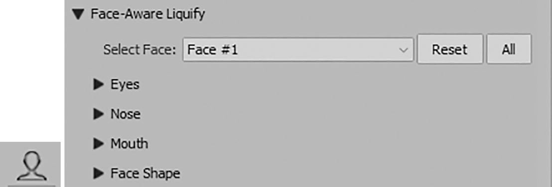
A panel for Face-Aware Liquify has a dropdown menu for selecting face and eyes, nose, mouth, and face shape sections. On the lower left is the face tool icon.
Liquify filter Face-Aware Liquify options

A dropdown menu for the select face option of Face-Aware Liquify exhibits a highlighted Face number 1 option above the Face number 2 option.
Face-Aware Liquify options for Select Face

A photograph of a female mannequin with a curved line on each side of the face. Face-Aware Liquify panel has its sliders in the eyes section set to 0.
Face-Aware Liquify options for eyes and guides on model

A section of a panel exhibits checkboxes under view options. Show image and show face overlay are checked, while show guides and show mesh are not.
Make sure that Show Face Overlay is enabled
Eyes: Adjust with the sliders to set the left and right eye for Eye Size , Eye Height, Eye Width, Eye Tilt, and Eye Distance between both eyes. Refer to Figure 9-165.

A set of multiple images of the eyes with changes due to various options under the eyes section of Face-Aware Liquify.
Use the overlay guides or sliders to adjust the eye’s size, height, width, tilt, and distance (before and after)

A screenshot of the pair of eyes of a female mannequin with eye size, eye height, eye width, eye tilt, and eye distance in the eyes section set to 0.
Adjusting each eye with different settings

A set of before-and-after screenshots of the pair of eyes of a female mannequin in relation to linked set values of eye size at 52.
Adjust both eyes at the same time when the link is enabled
Nose: Adjust with the sliders to set the Nose Height (-100,0, +100) and Nose Width (-100,0+,100). Guides on the Preview are also available to move the nose up or down or enlarge or shrink the nose. Refer to Figure 9-168.
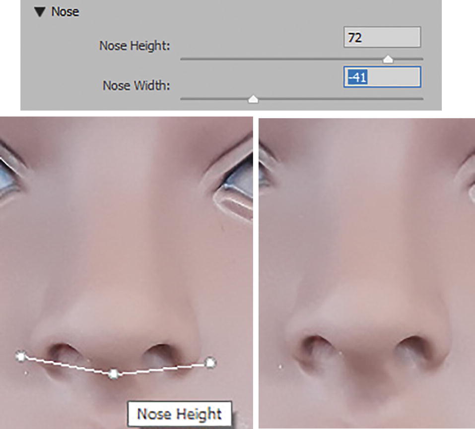
A set of before-and-after screenshots of the nose of a female mannequin with nose height and nose width changes at 72 and negative 41, respectively.
Use the slider or overlay guide to adjust settings for nose height and width
Mouth: Adjust with the sliders to set the Smile, Upper Lip , Lower Lip, Mouth Width, and Mouth Height. The range for each slider is -100, 0, +100. Guides on the Preview are also available to move around areas of the mouth. Sad or happy lips can be created when you move the smile slider left or right. Refer to Figure 9-169.

A screenshot of the sliders and overlay guides are used to edit the subject.
Use the sliders or overlay guides to adjust the smile, upper lip, lower lip and mouth width and height
Face Shape: Adjust with the sliders to set the Forehead , Chin Height, Jawline, and Face Width. The range for each slider is -100, 0, +100. Guides on the Preview are also available to move around areas of the face. Refer to Figure 9-170.

A screenshot of the sliders and overlay guides and a pop-up window for previewing is at the bottom.
Use the sliders or overlay guides to adjust the face shape for forehead, chin height, jawline, and face width, and click OK to exit when done
Once you have adjusted the face to your liking, click OK to exit the dialog box and look at the result.

A Layers panel exhibits a highlighted background copy layer above smart filters, which includes liquify.
A smart filter in the Layers panel stores the settings so that you can return to them any time
If you don’t get it right the first time, you can always try again later when you double-click on the Liquify filter name in the Layers panel.

A screenshot of the Face-Aware Liquify panel with the selected image.
Select the second face if you want to alter it as well

A screenshot of an illustrated face of a woman.
Use the Freeze Mask when you want to alter areas like ears so that you do not disrupt the hair while working with another brush

Three screenshots of several options in different panels with the highlighted spot healing brush, clone stamp, eraser, and blur tools, among others.
Upon leaving the Liquify tool, you can use anyone of these tools to make further cosmetic changes to your model on a blank layer
Let’s look at the final properties in the Liquify filter in reference to the current image.
Properties for Load Mesh Options and View Options

A section of a panel for the view options section exhibits checked show image, show face overlay, and show mesh with mesh size at medium and mesh color.
Liquify filter View options with Show mesh enabled in Preview
When the show mesh is enabled in the View Options tab, you also have the option to change options using the dropdown menus, such as the mesh size (Small, Medium, or Large) and mesh color (Red, Yellow, Green, Blue, Cyan, Magenta, or Gray) if it makes it easier to preview.

A section of a panel for the load mesh options exhibits loads mesh, load last mesh, and save mesh buttons.
Load Mesh Options
Clicking on the Save Mesh button will allow you to save the mesh you created as a .msh file if you need to use it for other projects that require similar alterations. With smart object layers, the mesh is saved and embedded in the file so you do not have to load it again. Refer to Figure 9-176.
According to Adobe, loaded meshes from other projects that are not the same size as current image are scaled to fit.

A section of a panel for the view options has enabled show guides, show image, and show face overlay options and an unchecked show mesh option.
Liquify Filter View options
The Show Image check box turns on or off the image preview. As noted earlier, Show Face Overlay allows you to see the preview of the Face Liquify options when you work with the Face tool.
Properties For Freeze Mask Options and View Options

A panel exhibits an opened Channels tab with layers. Below is a photograph of half of the second female mannequin's face with applied changes.
Mask options using a selection stored externally in the Channels panel

A dropdown menu for the first out of five mask options exhibits a checked transparency option and highlighted Alpha 1.
Selecting the Alpha 1 selection stored in the Channels panel

A set of 3 buttons labeled none, mask all, and invert all. The result of the selection is observed in the photograph of half of the second female mannequin's head with red-colored hair.
Mask Options. Choose Invert All for the current mask

A section of a panel for the view options has enabled show image and show face overlay options. Below is a checked show mask and red-selected option from the dropdown menu of mask color.
View Options for Show Mask when enabled
For a more through discussion on masks, selections, and channel creation outside the Liquify filter, make sure to check out my book Accurate Layer Selections Using Photoshop’s Selection Tools.

An illustration of an index finger of a right hand pointing to an L-shaped figure. It represents the icon for the forward warp tool.
Adjust the woman’s hair using the Forward Warp tool
Additional View Options
Besides the View options already mentioned as they relate to the preview image, mesh, and mask, you can also enable the Show Backdrop check box.

A section of a panel for the view options with enabled show image, show face overlay, show mask, and show backdrop options.
View options for Show Backdrop

A set of two photographs of the second female mannequin's mouth before and after disabling the show backdrop by unchecking its checkbox.
Disable Show Backdrop before you exit the Liquify filter so that you are not confused by the odd preview when you enter the filter again
Brush Reconstruct Options

An icon for the reconstruct tool and reconstruct and restore all buttons under brush reconstruct options are observed. Below is a dialog box for Revert Reconstruction with the amount slider at 76.
Brush Reconstruct Options for the Reconstruct tool and Revert Reconstruct dialog box

A pop-up window for previewing is observed with capsule-shaped Cancel and O K buttons.
Use the Preview check box to see the before after and click OK to exit the dialog box

A post-filter applications image of 2 female mannequins on the left. On the right is a Layers panel with a background copy layer above smart filters, which include liquify.
The model’s faces have been altered and the Liquify filter has been applied to the smart object Layer in the Layers panel
As you saw with the copper example, you can also use your smart filter mask to hide any area and with the Brush or Eraser tool to blend in any area to reveal parts of the original thumbnail.
For some additional related face distort, make sure to check out the Neural filter options in Chapter 10.
Tips: Working with Pet’s Faces with the Liquify Filter
Most of what you learned in these two Liquify projects you can apply to animal faces as well. However, as mentioned earlier, Liquify cannot detect pet faces. So, you must rely on the other Liquify brush tools to alter the animal’s face.

A set of multiple screenshots of the before-and-after use of a freeze mask option.
Appling a Freeze mask to the cat’s face before I use the Bloat tool on the eyes so as not to disturb the fur

A text that reads Liquify. A Layers panel has a highlighted liquify layer above smart filters, which include liquify.
Use the Liquify filter on text when its inside a smart object layer
Summary
In this chapter, you looked at several of the advanced filters and workspaces. Some are for lens correction, like Adaptive Wide Angle and Camera Raw, and others, like the Liquify filter, are for warping and distorting.
In the next chapter, you will look at more advanced filters, some of which can be used with smart objects layers and in combination with other smart filters on a single layer.