Chapter goal: Look at different ways that repeating patterns can be created and then warped.
Pattern creation is probably one of the more interesting and novel things you can do with a program like Photoshop. Patterning can be used for a variety of projects, including but not limited to
Backgrounds for websites and printed materials
Surfaces of parts of a selection of a design
Styles that can be applied to text or lettering
So, what are some tools that can be used to create patterns?
In this chapter, you’ll look at the Options panel for some tools that you should now be familiar with from the previous chapter (the Brush, Pencil, and Eraser tools) and you’ll look at how they can be used with the symmetry paint option and the Paths panel. Then you’ll do a brief review of the Pen tools , Path Selection tools , and Shape tools , and see how vector shapes can be made into a pattern. Next, you’ll take a scanned pattern and use the Offset filter and Clone Stamp tool to adjust the pattern. Then you’ll look at how the Libraries panel can be used for pattern generation. After creating the patterns, you’ll then look at how to reuse stored patterns, either for patterned backgrounds or textures in adjustment fill layers or layer styles. Lastly, you will look at how patterns can be used with some tools and then look at how to create a custom texture for the Filter Gallery, which you’ll explore in Chapter 8.
You can find the projects for this chapter in the Chapter 3 folder.

A duplicate image dialog box with the following option, duplicate semicolon C H 3 underscore symmetry paint dot p s d, and as semicolon C H 3 underscore symmetry paint dot copy.
Duplicate Image dialog box

A layer panel window with the following options, kind, normal, opacity 100 percent, lock, fill 100 percent, layer 1, and background.
Create a new layer in the Layers panel to paint on
Basic Pattern Creation

A context menu window for the paint options. A list of options for brush, pencil, and eraser tools is exhibited on the list.
Symmetry paint options for the Brush, Pencil, and Eraser tools

A context menu window for paint brush styles has the following options, size 81 pixels, hardness 100 percent, search brushes, and general brushes with 4 brush selections.
Brush Preset Picker and Hard Round Brush selected
As you progress with symmetry paint , you can alter the size, hardness, roundness, angle, or switch to a custom brush that you created in Chapter 2. Everyone’s pattern will be different.

An options panel for brush has mode normal, opacity 100 percent, flow 100 percent, smoothing ten percent, and angle 0 degrees, ok, cancel, add to shortcuts, color libraries, and a gradient field for the color selected.
Options panel for Brush and changing the foreground color in the Tools panel with the Color Picker
I will keep the Painting mode on Normal and Opacity at 100%, Flow at 100%, and Smoothing at 10% with the other icon buttons for pressure disabled and for the moment paint with a black foreground (Press D), but later I’ll use my Color Picker to switch to other colors. Refer to Figure 3-5.
Vertical
Horizonal
Dual Axis
Diagonal
Wavy
Circle
Spiral
Parallel Lines
Radial
Mandala

An Option panel image has the following options, x 1275.00 pixels, y 1650.00 pixels, w 100 percent, h 100 percent, angle 0 degrees, h 00, V 0.00.
Setting the Symmetry Paint Guide in the Transform Option panel

An options panel image in the warp setting has the following options, grid set to default, warp set to custom, bend 0.0, h 0.0, w 0.0.
Options panel in Warp settings to warp the path

An options panel image has the following icons, a stop sign, a check mark, and a prompt message that reads commit transform, enter.
Click the check in the Options panel to commit the settings for the path

A symmetrical pattern using brush painting. A vertical straight line with paralleled zigzag line runs across the length of the line is noted.
Brush painting vertical symmetry path

A context menu option for path. The category transform symmetry is highlighted.
Transform Symmetry path option selected

A layer panel with the options kind, normal, opacity 100 percent, lock, fill 100 percent, 3 layers labeled horizontal, vertical, and background.
Painting a different symmetry path on a new layer to test it

Six diagrams of symmetry paths. The illustrations are placed in different orientations.
Testing different symmetry paths with the Brush tool

Two diagrams with a context menu window for undoing steps for the symmetry path.
Use the History panel to undo steps as you paint with a symmetry path
Create two more blank layers, one for Radial and the other for Mandala, and paint one at a time on those layers as you select either option.

2 dialog boxes for radial and mandala symmetry have the options segment count with values 5 and 3, respectively.
Radial and Mandala Symmetry dialog boxes . Click in the Options panel to commit the transformation of the path

A diagram made using the radial symmetry brush tool. The illustration is in the shape of a broken pentagon with 5 concentric arc lines in the center.
Radial symmetry paint with Brush tool

A diagram made using the mandala symmetry paint brush tool.
Mandala symmetry paint with Brush tool

A context menu window depicts the hide symmetry and show symmetry sub-menu highlighted.
Hide and show options for the symmetry paint path

A diagram of the mandala radial. A layer panel window depicts the mandala radial layer selected.
Continue to paint on a layer with the last used symmetry path
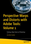
A context menu window for radial symmetry has the following options, segment count 10, o k, and cancel tab. 2 diagrams of the differing radial patterns are exhibited.
Paint with a new radial symmetry path with your Eraser or Pencil tool

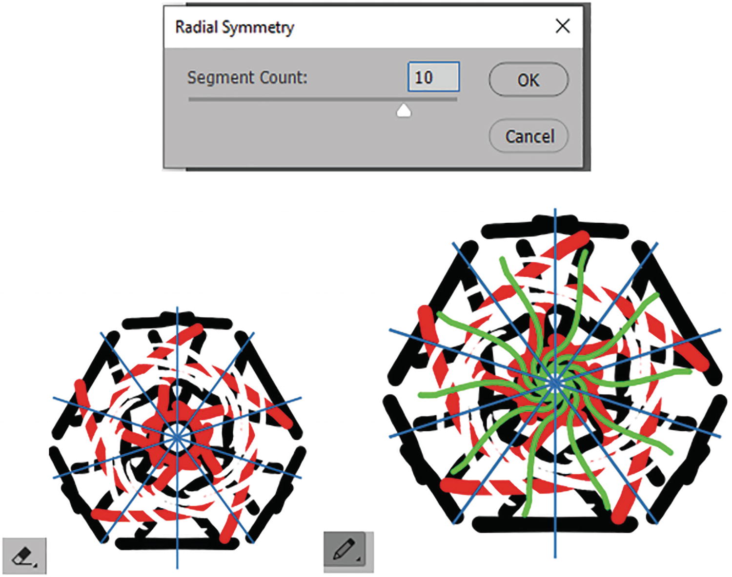
An illustration of the concentric radial pattern made with a custom brush tool.
Paint a new symmetry path with your custom brush

A context menu sub-option from the options panel. The symmetry off option is selected.
Select the Symmetry Off option in the Options panel to return to normal paint mode
However, we will just keep it on symmetry paint for the moment as we work on the next part of the project.
Project: Create a Custom Symmetry Paint Path
After experimenting with default symmetry paint paths, you may want to create a custom path. Another way this can be done is by using the Paths panel.

A tool tab from the options panel has the following options, mode normal, opacity 100 percent, flow 100 percent, smoothing 100 percent, and angle zero degrees.
Options panel for the Brush tool

A path panel window with channels and path tab. The path tab is selected with vertical and horizontal symmetry 1 on the list of options.
Use the Paths panel and the Pen tool to create a custom path
I talk about path creation in detail in my book Accurate Layer Selections Using Photoshop’s Selection Tools.

An options panel has the following options, path, make selection, mask, shape, a row of icons, auto add or delete, and align edges.
Options panel for the Pen tool set to Path mode

An options panel with the path tab selected has vertical, horizontal, dual axis symmetry, diagonal, and wavy symmetry 1 on the list of options.
Create a new path and select it in the Paths panel
Click the Create new path button and select the Path 1 path only. Refer to Figure 3-25.

A layer panel window with the blank layer 1 selected. A series of layers with symmetry patterns are exhibited on the list of layers.
Create a new blank layer before you create your custom path

An illustration of the triangle. A path tab with the context menu window toggled. The option for make symmetry path is selected.
Once the path is created with the Pen tool , from the Path menu choose Make Symmetry Path

An alert prompt window that signals the user when trying to make a symmetry path using the pen tool.
Alert message about using a symmetry path while using the Pen tool

An image of the symmetry path icon. The icon of a pyramid is exhibited labeled path 1.
Symmetry path icon in the Paths panel
A diagram of a series of arched lines with an image of a triangle superimposed in the center.
Use the Brush tool to paint with the new closed symmetry path
Each path has its unique characteristics when working with symmetry paint. So, with closed paths you may need to experiment several times on a new layer or use your History panel or Edit ➤ Undo or Ctrl/CMD+Z until you feel comfortable using this new path.

Two windows for the path panel. Option path 1 with an icon of a triangle is exhibited in both panels.
Reselecting the custom symmetry path in the Paths panel

A window for the path panel. The context menu option selected path is exhibited.
Reselecting the custom symmetry path in the Paths panel and choosing the Selected Path option

2 options represented by an icon of a stop sign and a check mark, with a text at the end that reads commit transform, enter is exhibited.
Click the check in the Options panel to commit the transformed symmetry path

A window for path panel option. The disable symmetry path from the context menu window is exhibited.
Disable the custom symmetry path in the Paths panel to return it to a normal path
You can see how this is the beginning of a custom pattern layer in Photoshop.

A window for the path panel option has symmetry off and last used symmetry on the context menu option. The symmetry off option is selected.
Turn the symmetry mode off in the Options panel to disable all symmetry paths in the Paths panel
We will continue to look at paths later in the chapter as well as in Chapters 5 and 8.
Make sure at this point to File ➤ Save your document. You can refer to file CH3_SymmetryPaint_final.psd if you need to review the layers so far.
Defining the Custom Pattern

A layer panel with multiple layers. The mandala radial eraser pencil is highlighted.
Flatten the layers in a copy of your file before you define a pattern and discard hidden layers

An illustration of the radial pattern and a layer panel window with the background layer highlighted.
Use the Rectangular Marquee tool to select your pattern from the background

A pattern name dialog box has the following options, name semicolon colorful symmetry paint, ok, and cancel.
Pattern Name dialog box

A pattern panel with subfolders of Trees, grass, water, and legacy patterns and more. The new pattern group option is selected on the context menu option.
Patterns panel with menu
We will use the Edit ➤ Define Pattern command a few more times again later in the chapter and then look at how they can be used with various tools.
Choose Select ➤ Deselect to deselect the pattern.

A dialog box labeled Group name has Ch3 patterns entered in the name tab, and tabs ok and cancel. Another dialog box has the options name c h 3 patterns, with create new group icon selected.
Group Folder dialog box created for the Patterns panel and file format to save your patterns for use by others
Patterns can be saved or exported by selecting the folder, and from the menu choosing Export Selected Patterns. They are saved as a .pat file and then can be imported by choosing from the menu Import Patterns. In this chapter’s project folder, I have saved the current patterns we are using if you want to use them as well. Refer to Figure 3-40.
Later, we will apply the patterns to various backgrounds.
You can close the copy of your flattened file without saving changes but save your layered .psd files for future reference.
Vector Shape Patterns

The three options panel contains the selections for pen tools, path selection, and shape tools.
Tools panel collections of Pen tools, Path Selection tools, and Shape tools
While working in this section, if you need to practice, File ➤ Open CH3_SymmetryPaint.psd as it is just a blank file for you to create layers on and make an Image ➤ Duplicate of the file for practice.
Pen and Shape Tools Review

A tool tab has the path options selected. The option path is selected from the dropdown menu.
Options panel for the Pen tool set from Path mode to Shape mode
Pen Tools

A context menu option for the pen tool has seven options on the dropdown list.
The Pen tool collection
Pen Tool (P)

An image of a straight line with numbers 1 and 2. 1 reads click, and 2 shift plus click.
Use the Pen tool to draw a straight line

A diagram of 2 semi-circles with instructions from 1 to 3. 1 reads click, 2 click plus drag downward arrow, and 3 click plus drag upward arrow.
Use the Pen tool to draw curves

2 diagrams with numbered instructions 3 and 4. First illustration labels, 3 click plus alt or option, 4 click, 2nd illustrations labels, 3 click plus alt or option drag out handle, 4 click.
Use the Pen tool to draw a straight or a curved line that changes direction

A diagram with a numbered instruction labeled 5 click or click plus drag.
Use the Pen tool to close the open path for your shape
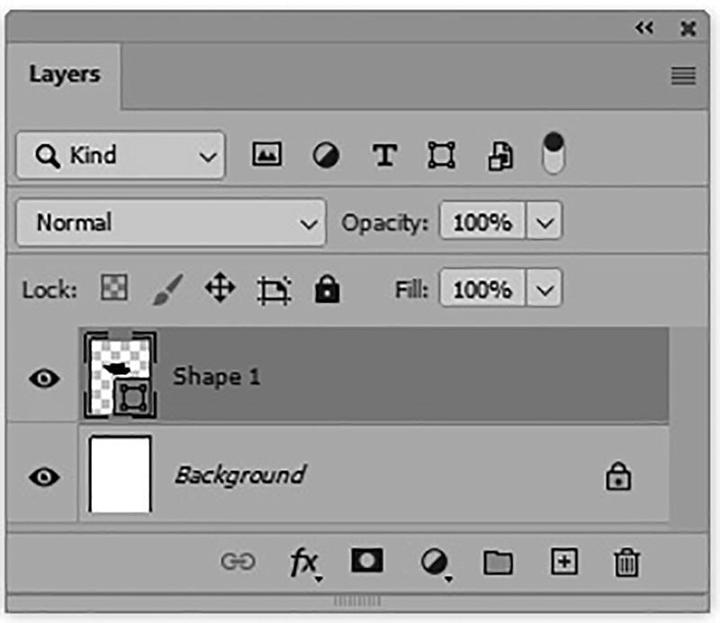
A layer panel window with the first layer selected reads shape 1.
Vector shape layer in the Layers panel
Pen Tool Options

An options panel with the path tab toggled, and shape option selected. At the bottom is another panel with folders for the color palette swatches.
Options panel for the Pen tool. Use the dropdown menu to change the swatches color for a fill or stroke of the shape
No Color (square with red slash)
A gradient from the list and alter the gradient’s slider order (color and opacity stops, opacity midpoint), opacity (0-100%), style (Linear, Radial, Angle, Reflected, Diamond), angle (-180, 0, 180), reverse gradient colors, scale (1-1000%), Align with Layer, and Method (Perceptual, Linear, Classic). These gradients can be found in the Gradients panel. Refer to Figure 3-50.
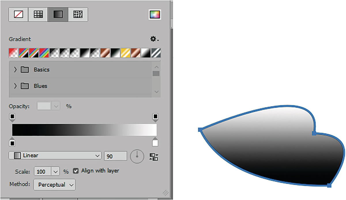
An options panel for pen tool has the options gradient, basics, blues, opacity, linear, scale, align with layer, and method perceptual.
Options panel for the Pen tool. Use the dropdown menu to change the gradient color for the fill or stroke of the shape
Or a pattern and alter the scale (1-1000%) and angle (-180, 0, 180). These patterns can be found in the Patterns panel. Refer to Figure 3-51.

An options panel for the pen tool has the options pattern with subfolders for the different patterns available, scales 100, and angle at 0 degrees. A diagram of an irregular shape filled with different colors and random shapes.
Options panel for the Pen tool. Use the dropdown menu to change the pattern for the fill or stroke of the shape
Alternatively, you can choose a color from the Color Picker on the far right of the menu. The gear menu on the right will change options according to the type of fill or stroke chosen. Recently used items are displayed in a row depending on whether swatch, color, gradient, or pattern. Refer to Figure 3-51.
For now, set the fill and stroke back to a solid color. Refer to Figure 3-42.
Size: 0 px - 1200 px
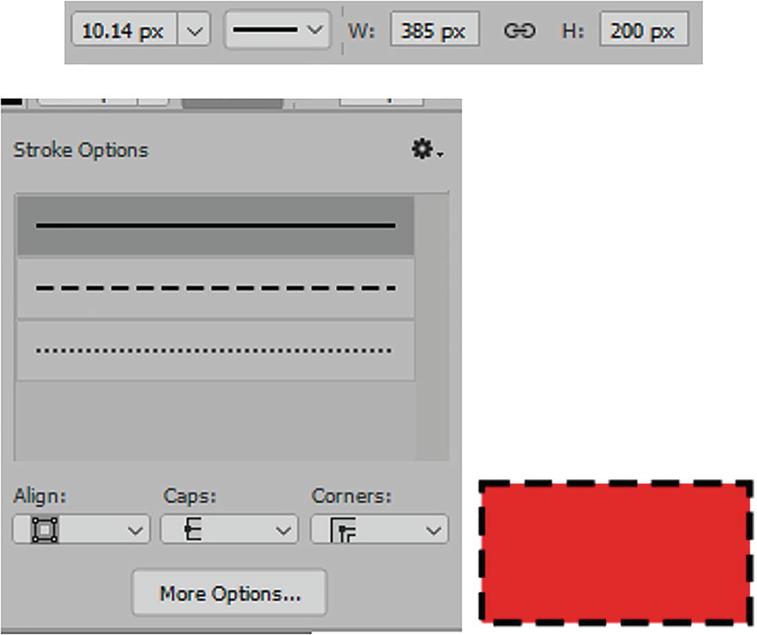
Shape stroke type: This menu includes various stroke options . They allow you to align the stroke and add caps and corners to the stoke. The gear menu allows you to save custom strokes. Click the More Options button and the dashed line check box if you want to create a dashed and gapped preset line. Otherwise, by default, the line will be solid. Refer to Figure 3-52 and Figure 2-53.

The options panel has the following tabs, stroke 10.14 pixels, and a line icon with a dropdown button.
Stroke color, width, and style in the Options panel

A set of panel options has stroke options, stroke, align, caps, and corners.
Options panel with additional stroke style options for a shape from the dropdown menu

An options panel has the tabs for w 1100.06, H 611.28 pixels, and the pixels option is selected in a drop-down menu.
Set the unit of increments for the shape’s width and height and link to scale proportionality

Three icons for the options panel and each has a drop-down button on the side.
Options panel menus for path operations, alignment, and arrangement

3 layer panel tiles labeled shape 1 copy, shape 1, and shape 1 copy, with a context menu option merge shapes control + e highlighted.
Merge two or more shapes layers onto one layer so they share the same attributes
The path operations are New Layer, Combine Shapes, Subtract Front Shape, Intersect Shape Areas, Exclude Overlapping Shapes, and Merge Shape Components. This works similarly to the Properties Pathfinders area to create live shapes, which we’ll look at later. Refer to Figure 3-57.

5 overlapping images in the shape of sideward-tilted hearts with the panel context menu exclude the overlapping shapes option selected.
Options panel for path operations : Combine, Subtract, Intersect, Exclude, and Merge Shape Components from Intersect Shape areas
Path Alignment: When two or more shapes are selected, you can align the shapes (left edges, horizontal centers, right edges, top edges, vertical centers, bottom edges) or distribute the spacing vertically or horizontally by clicking one of the options in the menu. To create and select more duplicate paths on one layer, you need to use the Path Selection tool, which we will review in the next section of this chapter. Refer to Figure 3-58.

An options panel has the following options, align, distribute, distribute spacing, and on the side are three heart-like shapes.
Use path alignment on two or more selected shapes
Path arrangement: When paths overlap on a shape layer, you can change the order, bring a shape to front, forward, or send a shape backward or to the back of the stack. Refer to Figure 3-59.

A dropdown menu option has a list for bring shape to front, forward, backward, and to back, and 3 overlapping images of hearts at the bottom.
Bring and send shapes when one shape is selected

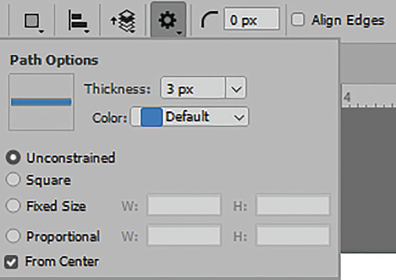
A dropdown tab for path option has a thickness of 3 pixels, color default, and a rubber band option.
Path Options for the Pen tool

A dropdown options panel for tools option has add anchor, deleter anchor, and convert point tool options.
Auto add or auto delete points rather than using those tools in the Tools panel

A tickbox option has a label that reads align edges.
Align Edges check box option
Freeform Pen Tool (P)
The Freeform Pen tool is like the Pen tool. It binds to edges of selection if the magnetic option is chosen; otherwise, you can drag in a circular motion to create a path.
Freeform Pen Tool Options

An illustration of a sphere with gradient glowing behind it, and a tool tab at the bottom with options shape, fill, strokes, W, H, magnetic, and align edges.
Options panel for the Freeform Pen tool and drawing with the tool on an image with normal or magnetic settings
This tool is not relevant to the topic of this book, and I prefer to use it in Path mode so that I can see the image below for a more accurate trace, before turning it into a shape. But if you would like more details on how to use it for paths, you can refer to my Photoshop Selections book mentioned earlier the chapter. This book shows how a path can be turned into a new shape layer while in Path mode.
Content-Aware Tracing Tool (P)
Like the Pen tool, you can attempt to draw a path around a distinct shape and image with the Content-Aware Tracing tool , and while you draw, it creates a preview selection of the path before you click the next location.
Content-Aware Tracing Tool Options

A tool tab has the options shape, fill, stroke, W, H, and four icons for path tool.
Options panel for the Content-Aware Tracing tool
However, in the next section, there are additional tracing options that include creating paths from detected edges, extending currently selected paths with detected edges, and trimming traced paths.

A cutout image of a flower with the lines of a tracing tool.
Options panel for the Content-Aware Tracing tool’s additional options and preview of trace as you draw the shape
See the Pen tool for details on the Align Edges check box.
This tool is not relevant to the topic of this book, and I prefer to use it in Path mode so that I can see the image below for a more accurate trace, before turning it into a shape. If you would like more details on how to use it for paths, you can refer to my Photoshop Selections book mentioned earlier the chapter. This book shows how a path can be turned into a new shape layer while in Path mode.
Curvature Pen Tool (P)
Like the Pen tool, the Curvature Pen tool allows you to create curved paths around a drawing to create a closed path.
Curvature Pen Tool Options

A tool tab with options shape, strokes, W, H, and align edges, and circular shape with outlines that has 5 points.
Options panel for the Curvature Pen tool and a shape drawn with the tool
This tool is not relevant to the topic of this book, and I prefer to use it in Path mode so that I can see the image below for a more accurate trace, before turning it into a shape. If you would like more details on how to use it for paths, you can refer to my Photoshop Selections book mentioned earlier the chapter. This book shows how a path can be turned into a new shape layer while in Path mode.
Add Anchor, Delete Anchor, and Convert Point Tools

A dropdown option has add anchor, delete anchor, and convert point tool.
Add Anchor, Delete Anchor, and Convert Point Tools

Two overlapping images in the shape of a heart with an image of a pen tip at the bottom.
Add an anchor point to a path

2 images of a heart figure with segmented points and a pen tip icon depict the process of deleting an anchor point.
Delete an anchor point from a path

4 images with segmented outlines depict the process of converting an anchor point at different orientations.
Convert an anchor point to either straight or curved
If you find one of your anchor points is twisted while drawing, the Convert to Anchor Point tool is the best option to use to untangle it. Just click and drag in the opposite direction.

A prompt message reads no options for the convert point tool.
The Options panel has no additional options for the Add Anchor, Delete Anchor, and Convert Point tools
Path Selection Tools
Path Selection tool (A): Move or transform the entire path or shape
Direct Selection tool (A): Move a point or handles to distort or adjust the path. Refer to Figure 3-72.

A dropdown menu has the options path selection tool and direct selection tool.
Tools panel with Path Selection and Direct Selection tools
Path Selection Tool Options

A tool tab for options panel has select set to all layers, fill, strokes, W, H, align edges, and constrain path dragging.
Options panel for the Path Selection tool
The next section allows you to set Path Operations, Path Alignment, and Path Arrangement, and this I find is easier to do with the Path Selection tool rather than then Pen tool. However, refer to that section for more details. Refer to Figure 3-73.

2 overlapping images of a circle with a cross-section line on the intersection, depict the process of duplicating a shape.
Creating a duplicate shape with the Path Selection tool

2 sets of identical images depict the process of multiple shape selection. One image set has a segmented outline surrounding the shapes.
Selecting multiple shapes with the Path selection tool by dragging a marquee around them

A tool tab has path options toggled with thickness set to 3 pixels and color selection set to default.
Path options for the Path Selection tool
Direct Selection Tools Options

A tool tab panel for options has select set to all layers, strokes set to 5 pixels, W 197.00, H 296 p x, align edges, and constrain path dragging.
Options panel for Direct Selection tool
When you want to select more than one point, drag to draw a rectangular marquee around the items you want to select or Shift+Click on each point one at a time. Refer to Figure 3-78.

2 identical heart-shaped images depict the process of selecting multiple points. The shape outline has multiple segmented points and 2 vertical bars for adjusting the marquee points.
Selecting multiple points with the Direct Selection tool by dragging a marquee around them
Shape Tools

The 2 options panel has rectangle, ellipse, triangle, polygon, line, and custom shape tool under the context menu option for shape.
Shape tools in the Tools panel and the Options panel set to Shape mode

2 options panel tool tab. For pixels, the options are pixels, mode normal, opacity 100 percent, anti-alias, for shape, shape, stroke, W, H, and align edges.
Options panel for a shape either set to Pixels or Shape mode
Coming back to Shape mode, let’s review the next six tools.

A dialog box for rectangle creation has width of 420 pixels, height of 420 pixels, 4 tabs of 5 pixels for radii, from center, o k, and cancel. Four illustrations of two rectangles and two squares.
Create Rectangle dialog box and various created rectangles and squares that can be further transformed with the Path Selection tool when the cursor changes shape

A dialog box for ellipse creation has a width of 420 p x, height of 420 p x, from center, o k, and cancel. Three illustrations of 2 oval shapes and a circle.
Create an Ellipse dialog box and various created ellipses and circles that can be further transformed with the Path Selection tool

A dialog box for create a triangle has width of 420 pixels, height of 420 pixels, equilateral, a corner radius of 0 pixels, from center, o k, and cancel. Four diagrams od triangles in different sizes.
Create a Triangle dialog box and various created triangles that can be further transformed with the Path Selection tool

A dialog box for create polygon has width of 420 pixels, height of 420 pixels, symmetric, number of sides, corner radius, star ratio of 100 percent, smooth star indents, from center, o k, and cancel. Six diagrams of pentagons of different sizes.
Create a Polygon dialog box and various created polygons and stars that can be further transformed with the Path Selection tool
From Center, when enabled, creates the polygon from a center point of where you clicked in the canvas. Click OK and once the Polygon is created and selected with your Path Selection tool, use the circle (live corners widget) to adjust the radius and the bounding box handles for further moving, scaling, and rotation. Refer to Figure 3-84.

Three arrow shapes were created using the line tool. 2 of the line has arrowheads.
Lines creates with the Line tool. Some have arrow heads

2 images of light bulbs made using the custom shape tool option. Three context menus of shapes.
Custom shapes created with the Custom Shape tool and custom shapes stored in the Shapes panel and additional options in its menu

A context menu has a panel with the following options, path selection tool A and direct selection tool A.
Path Selection and Direct Selection tools
To select individual points, use your Direct Selection tool. Refer to Figure 3-87.
Shape Tool Properties
Since many of the Shape tool properties are similar for most tools when in Shape mode, as with the Pen tool, I will just look over the main key differences for each tool. Otherwise, refer to the Pen tool for more details.
Rectangle Tool Options and Properties

An options panel has the following options shape, fill, stroke, W 385 p x, H 200 p x, and align edges. Two diagrams of rectangles and two diagrams of squares.
Options panel for the Rectangle tool and various rectangles and squares with various fill and stroke settings
An options panel for the rectangle tool has 10. 14 pixels, W 385 pixels, H 200 pixels, stroke options with different line selections, align, caps, and corners. A diagram of a rectangle.
Options panel for Rectangle tool stroke width, styles, width, and height with a link to constrain proportions and a custom rectangle with fill and stroke

3 context menu panel for the rectangle tool path contains different options for aligning and arranging the shapes. A diagram of a rectangle and two diagrams of squares.
Options panel for Rectangle tool path operations , alignment, and arrangement for various rectangles and squares with similar fill and stroke settings on a single layer

A layers panel window with the existing layers exhibited. Rectangle 1, Shape 1, shape 1 copy, line 3, path, and direct selection tools are observed.
Layers panel with two shape layers merged or use Path Selection tool to duplicate shapes

A layer panel window illustrates the workflow of moving separate layers. Rectangle 2 copy, rectangle 2, and rectangle 1 layers are highlighted.
Use the Move tool Options panel to move shapes on separate layers when selected
A rectangle tool options panel has a thickness of 3 pixels, color default, unconstrained, square, fixed size, proportional, from the center.
Rectangle tool Path Options menu
The last checkbox, when enabled, allows you to align edges to the pixel grid. See View ➤ Show ➤ Grid.
Additional Properties Panel Options
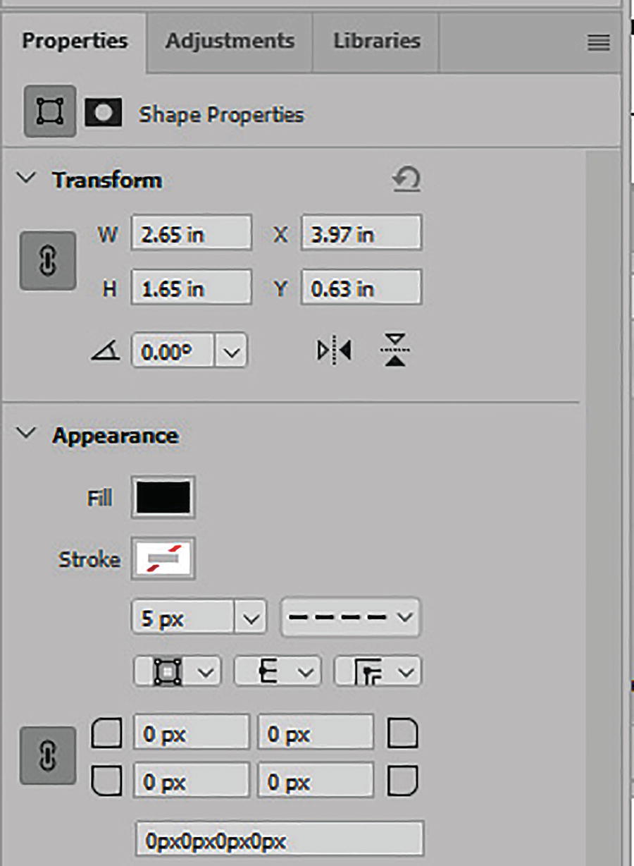
A properties panel for the rectangle tool has transform, w 2.65 inches, 3.97 inches, H 1.65 inches, y 0.63 inches, angle 0.0 degrees, appearance, fill, and stroke.
Rectangle tool Properties panel
Lastly, you can use the Pathfinder options to alter how the shapes combine. Similar settings are also located in the options panel above as Path Operations .
Combine shapes (Shift)
Subtract front shape (Alt/Option)
Intersect shape areas (Shift +Alt/Option)
Exclude overlapping shapes (does not appear to have a key command, so just use the button in the properties or Path Operations dropdown in the Options panel)

A window panel for properties has shape properties, transform, appearance, and pathfinder.
Options panel and Pathfinder options for live shapes in the Properties panel. Cursor icons change when you combine, subtract, intersect, or exclude overlapping shapes

A layer panel window with 4 layers selected. Outside the panel are 4 rectangular shapes, 2 of them has broken lines that represent the pathfinder tool.
Selected layers when Pathfinder settings of combine, subtract, intersect, or exclude are enabled
Live Pathfinder options are not available for shapes created with the Pen tool.
Ellipse Tool Options and Properties

An options panel for the ellipse tool has path options, thickness 3 pixels, color default, unconstrained, circle, fixed size, proportional, and from the center. Two oval shapes and a circle shape diagram are depicted on the right.
Options panel for the Ellipse tool , path options and various ellipses and circles with various fill and stroke settings
The last checkbox, when enabled, allows you to align edges to the pixel grid. See View ➤ Show ➤ Grid.

A properties panel for ellipse tool shape has the following options, transform, W 1.57 inches x 3.16 inches, H 1.49 inches Y 8.53 inches, angle 0.0 degrees, appearance, fill, stroke, 5 p x, and pathfinder.
Properties panel for the Ellipse tool
Triangle Tools Options and Properties

An options panel for the triangle tool has the following options, path options, thickness of 3 pixels, color default, unconstrained, equilateral, fixed size, proportional, and from the center. Three diagrams of triangles of different shapes.
Options panel for the Triangle tool , path options, and various triangles with various fill and stroke settings
The last checkbox, when enabled, allows you to align edges to the pixel grid. See View ➤ Show ➤ Grid.

A properties panel for the triangle tool shape has transform with the dimensions for width and height in inches, appearance, fill, stroke, 5 pixels, and pathfinder.
Properties panel for the Triangle tool
Polygon Tools Options and Properties

An options panel for the polygon tool has a thickness of 3 p x, color default, unconstrained, symmetric, fixed size, and proportional. freeform, star ratio 100 percent, and from center. Five diagrams of pentagons in different sizes.
Options panel for the Polygon tool , path options, and various polygons and stars with various fill and stroke settings
The last checkbox, when enabled, allows you to align edges to the pixel grid. See View ➤ Show ➤ Grid.

A properties panel for the polygon tool has a transform sub-menu with the dimensions for width and height in inches, appearance, fill, stroke, 10.14 pixels, smooth star indents, and pathfinder.
Properties panel for the Polygon tool
Line Tool Options and Properties

A path options panel for the line tool has thickness 3 pixels, color default, live shape controls, arrowheads, start, end, width 5 pixels, length 10 pixels, and concavity of zero percent.
Options panel for the Line tool, path options, and various lines with various fill and stroke settings
The last checkbox, when enabled, allows you to align edges to the pixel grid. See View ➤ Show ➤ Grid.

A properties panel has the parameters for the line tools. These are transform, appearance, and pathfinder.
Properties panel for the Line tool
Custom Shape Tool Options and Properties

An options panel for the custom shape tool has a thickness of 3 pixels, color default, and the unconstrained options highlighted. Outside the panel are images of a lightbulb, and 2 jigsaw puzzle pieces.
Options panel for the custom shape tool , path options, and various shapes with various fill and stroke settings

2 panels for the custom shapes tool. The first panel has folders labeled leaf trees, wild animals, boats, flowers, legacy shapes and more, and the second panel has 12 images of trees.
The custom Shapes dropdown menu is the same as the Shapes panel
The last checkbox, when enabled, allows you to align edges to the pixel grid. See View ➤ Show ➤ Grid. Refer to Figure 3-106.

A properties panel for the custom shape tool has the following options, transform with the dimensions for width and height in inches, appearance with fill and stroke options, and pathfinder.
Properties panel for the custom shape tool

6 images of jigsaw puzzle pieces with different patterns on them. The context menu option for copy and paste shape attributes is exhibited.
Use the Layers panel to copy and paste attributes from one selected shape to another

A panel for history illustrates the process of undoing steps taken.
Use the History Panel to undo steps
After practicing creating shapes with your Pen tools, Selection tools, and Shapes tool, make sure to File ➤ Save your document as a .psd file. You can refer to file shapes.psd to see my progress.
Project: Create a Custom Shape and Then Turn It into a Pattern or Brush
Once you have created some shapes with your shape tools, you can then create a custom shape . Let’s try that now.
File ➤ Open the file Ch3_CustomShape.psd. This file is square 500 px by 500 px because a square area is best to create my eventual pattern. Make an Image ➤ Duplicate of the file for practice.

A layer panel has 2 layers. The ellipse 1 and background layers are exhibited. Ellipse 1 is highlighted.
Shape layer in the Layers panel

A tool tab for the ellipse option tool has shape, fill, and stroke of 10.14 pixels.
Ellipse tool options
Hold down the Shift key and drag out to draw and add several more circles in varying sizes and then use the Move tool or Alt/Option+Drag with your Path Selection tool to move and duplicate them and add them around the first ellipse to arrange them into a pattern. It does not have to be the same as mine.
To scale a shape with the Path Selection tool , select the shape and then hold down the Shift key to constrain proportions with the bounding box handles. Alt/Option+Shift will allow you to scale from the current center point.
When a shape is selected with the Path Selection tool, you can also use the arrow keys on your keyboard to nudge it into place.

A layer panel has a total of 10 layers with different shapes. The second layer labeled ellipse 2 copy is highlighted, and a segment of the image outside the panel is exhibited.
Multiple ellipses on various layers in the Layers panel and moved with the Path Selection tool

An image of a pattern made using path selection tool. One of the corners with a square figure is selected using path selection tool.
Use the Path Selection tool when a shape is selected to scale or rotate further

A layer panel with all the 10 layers selected. Outside the panel is an image with an overlapping line across the components of the image using a path selection tool.
All paths are selected in the Layers panel while using the Path Selection tool

A dialog box for naming a shape has the option name semicolon shape 727, o k, and cancel buttons.
Shape Name dialog box
The shape is now added to the Shapes panel with any other shapes that were created by yourself or others.

A dialog box for naming a group folder has the option name semicolon C h 3 custom shapes, o k, and cancel buttons. Panel C h 3 custom shapes have 2 custom images.
Create a group folder to store custom shapes

A context menu for shapes panel has the export selected shapes option selected.
Export or import custom shapes from the Shapes panel menu

A pattern panel has a search pattern search field. A pattern is selected from the bottom panel.
Add a custom pattern to the group folder in the Patterns panel

A brushes panel window has the following options, name C h 3 underscore custom shape copy, ok, and cancel buttons. Another panel of custom brushes Ch 1.
Add a custom brush to a group folder in the Brushes panel and preview with the Brush Settings panel
Wow! One pattern can be used in three different tools! That’s good value.
File ➤ Save your custom shape file at this point. You can refer to my file, Ch3_CustomShape_final.psd. And you will find the files for the custom shapes, patterns, and brushes in the chapter’s project folder.
Project: Patterns with the Offset Filter
Once you have created various designs with your brushes and shapes, you can see how they can be defined as patterns. However, maybe you have a photo of a textile or a pattern that you created and then made a photo or scan. How can you create a seamless pattern from an image? To create seamless patterns that flow correctly, you need to find a way to check how the pattern appears at the edges so that one side flows into the other. You can do that in two ways. The first is to use the Offset filter .
File ➤ Open file Pattern6.psd in the Chapter 3 Cloth_Patterns folder and make an Image ➤ Duplicate of the file as you did in Chapter 2 and click OK.

A photo of a cross-stitch pattern. The pattern is in the shape of a diamond.
A custom cross-stitch pattern with texture

A dialog box setting for an image has image size 1.76 meters, dimensions 827 pixels x 745 pixels, width 2.757 inches, height 2.483 inches, resolution of 300 pixels per inch, resample, ok, and cancel buttons.
Image Size dialog box settings

A panel for image size contains the image size, dimension in pixels, and resolution. The field for width is selected with a value of 2.757.
Changing the Image Size dialog box settings from inches to pixels
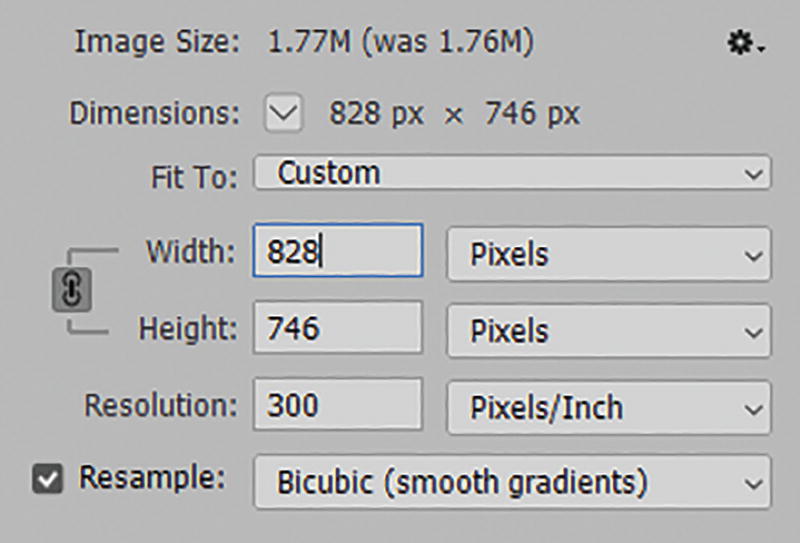
An image size dialog box has image size, dimensions in pixels, width and height in pixels, resolution in pixels per inch, and resample in bicubic, smooth gradient.
Increasing the image size’s width and height proportionately

An image size dialog box has image size, dimension in pixels, fit to custom, width and height in pixels, resolution, and resample. The field for height has a value of 828 pixels.
Making the pattern square by stretching and increasing the height slightly
This pattern is now 828 px wide and 828 px high. The resolution is 300ppi for print. Remember that if you are planning to use your pattern for a website, then after you create the background, set the resolution to 72ppi. While not relevant to the topic of this book, you can see example files of that resolution in my book Graphics and Multimedia for the Web with Adobe Creative Cloud. However, I think it is best to create the initial pattern at 300ppi because, depending on your project requirements, later you can use the background for a variety of print or web projects and are not restricted to one media.
Also, always keep a backup of your original pattern in an undistorted state. This is why we are working on a copy: in case we want to use this pattern for a different project.
Now I want to create a repeating pattern with seamless edges. I prefer working with a square canvas that has an even number of pixels. It makes the math in the next step easy to figure out. However, depending on the complexity of your pattern, you can make your file dimensions larger or smaller than mine or use a rectangular pattern instead. Just make sure each side has an even number of pixels.
Offset Filter

An offset panel under image size options has horizontal and vertical, o k, cancel, and undefined areas with the option wrap around selected.
Offset filter and preview of current pattern
You willl notice that there are a few lines where the edges are not meeing correctly. This is due to some of the canvas that borders where I stitched and it cannot be helped with handmade items. In the Offset dialog box, click OK.
Touching Up the Pattern

A layer panel has three layers exhibited. The first layer labeled layer 2 is selected.
Create a new layer to work with the Clone Stamp tool

A context menu displays 2 options, clone stamp tool, and pattern stamp tool. Below is the option panel of the clone stamp tool.
Clone Stamp tool and its Options panel
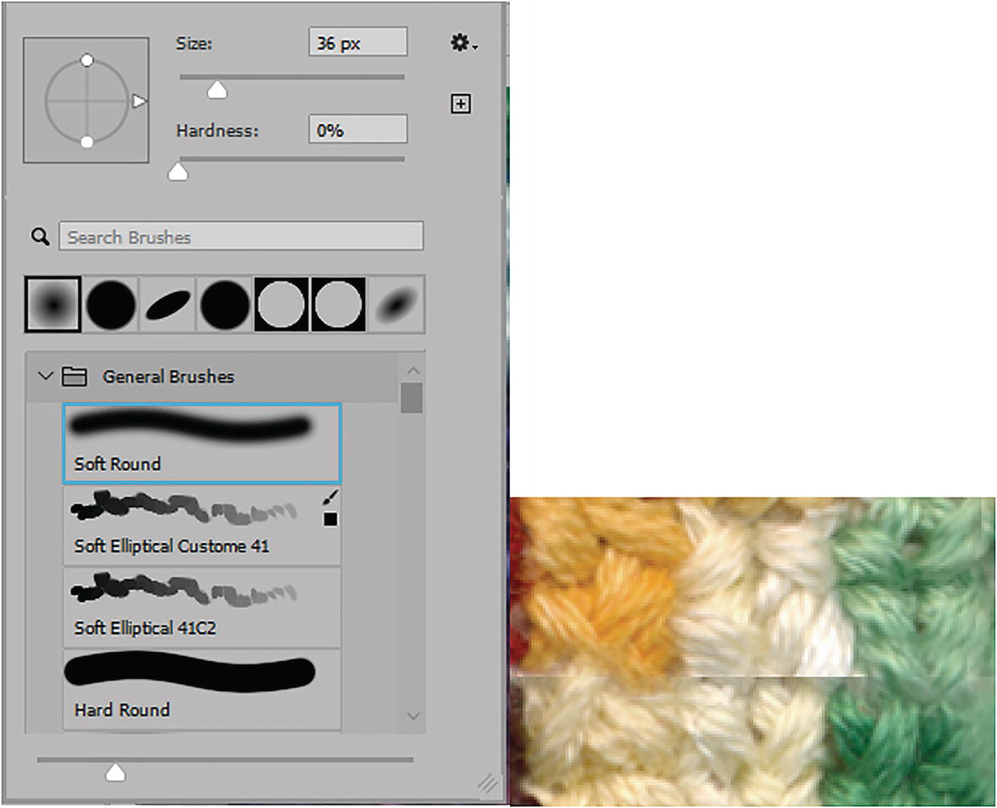
A window displays options on different brushes, soft round, soft elliptical custome 41, soft elliptical 41 C 2, and hard pound. On the right is a photo of 3 seams that are cloned on the new layer.
Options panel for Brush Picker Presets for clone stamp and cloning covering parts of the seam on the new layer

A toolbar for the eraser tool. The options include mode, opacity, flow, smoothing and erase to history.
Options panel for Eraser tool
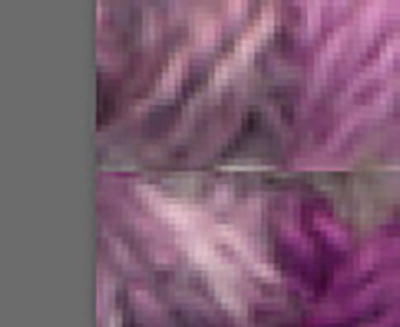
A close-up view of the edge of the pattern of the seam. Below is its close, done using the clone stamp.
Close-up of edge of pattern that is being cloned with the clone stamp

2 windows display the layers section, where the Layer 2 visibility is turned off and on.
Turning off and on the visibility of the area being cloned on the new layer

A photograph of diamond patterns made of different colored seams. Below is a window that displays the layer options and under it are turned on layer 3, layer 2, layer 1, and background. Layer 3 is selected.
Combining the pattern and cloned layers as a new merged and complete layer
At this point File ➤ Save your document as a .psd file. You can refer to my file so far, Pattern6_final.psd.
Pattern Preview

A warning message from Adobe Photoshop reads Pattern Preview works best with small objects. Transforming pixel layers may show unexpected results. Below are the O K and More Info buttons.
Pattern preview info warning

A photograph of a series of diamond shapes made of seams. The thin guide indicates the center.
Pattern in Pattern Preview with thin blue guide indicating center
The thin blue line is where your original canvas area is. Looks good to me.
For more details on how to use Pattern Preview, refer to this link: https://helpx.adobe.com/photoshop/using/pattern-preview.html .
To get out of this view, choose View ➤ Pattern Preview again.
Defining a Pattern

A window of Pattern Name displays a box for Name with an entry that reads, Pattern 6. Beside it is the O K and Cancel buttons.
Pattern Name dialog box

A window displays an open Patterns option. Below is the open C h 3 Patterns folder, and under it are 11 different patterns.
Pattern added to the group folder in the Patterns panel
If you enjoyed this pattern creation process, I have five other patterns in the Cloth_Patterns folder you can practice with and repeat these steps.
Earlier in the chapter you saw how to add patterns to vector shapes. Later in this chapter we will start using our patterns in backgrounds to fill areas. However, before we do that, I will show you a second way to create a unique repeating pattern from any image.
Libraries Panel: Adobe Sensei Capture Extract from an Image to a Pattern
Colors and color themes
Gradients
Character styles
Layer styles
Brushes
Graphics
Patterns

A window displays the open libraries option, and under it are several assets that include Patterns, which have 2 different samples.
Libraries panel that stores various assets including patterns
You can learn more about the Libraries panel as Adobe updates it frequently. Refer to these related links to explore how additional assets can be used in libraries with other Adobe apps : https://helpx.adobe.com/photoshop/using/cc-libraries-in-photoshop.html and https://helpx.adobe.com/illustrator/using/creative-cloud-libraries-sync-share-assets.html .
Most libraries in other Adobe apps have similar importing and exporting features. However, Photoshop appears to be the only one so far that has an Adobe Sensei Capture Extract from Image to create patterns from any image. Let’s see how that works.
Project: Patterns from Cloth Pattern Part 2
To start, make sure that you have your Photoshop Libraries panel visible. If you don’t have a library, create one first or use one of the current libraries you have open for this project.

A window displays an open Libraries option. Under it is a Create new library command and beside is a pop-up context menu with the top option, create new library.
Creating a new library to add patterns to

A window for create new library has an entry called Photoshop Patterns, with the create button below. Beside is another window that displays the Photoshop Patterns under the open libraries option, and the main text at the center reads, Start building a library.
Creating a new library in the Libraries panel

A window displays an open layers option with turned-on layer 1 and background under it. A pop-up context menu on the right displays, an extract from image, and below is a photograph of a checkered pattern.
Selecting a layer and choosing to extract from images in the Libraries panel
To create a pattern, make sure your current background layer is visible and Layer 1 is selected. Then, from the Libraries panel, click the plus icon (add elements). Rather than choosing the graphic or the current foreground color, choose the option Extract from Image.

A dialog box is titled extract from image, with the patterns option open. Below is an image of a pattern, and beside are features, pattern, color mode, scale, and rotation, and at the bottom right is a zoomed version of the pattern, with an inverted triangle at the center.
Extract from Image dialog box
The first tab which we will be looking at is the Patterns Tab. However, if you want to create and clean up a graphic shape, add swatches for custom Color Themes or Gradients, or find similar Type fonts make sure to check out those options on your own afterwards as it is not part of the topic of this book.
https://helpx.adobe.com/photoshop/using/capture-extension-in-libraries-panel.html
https://www.adobe.com/products/capture.html
PNG (.png)
JPEG (.jpg and .jpeg)
SVG (.svg)
Bitmap (.bmp)
ICO (.ico)
Webp (.webp)
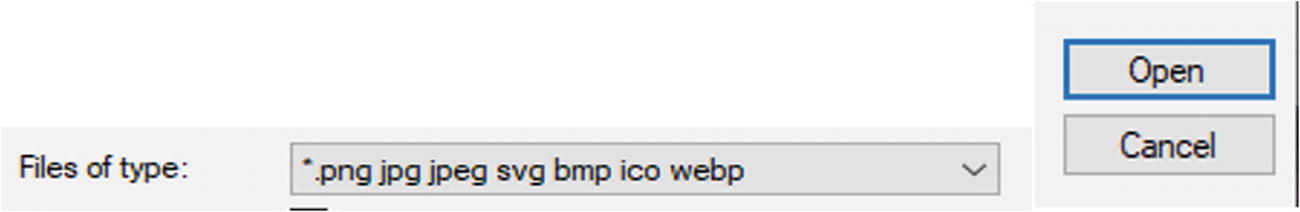
A dialog box displays a dropdown box for files of type, set to dot p n g, j p g, j p e g, s v g, b m p i c o w e b p. Beside it are open and cancel buttons.
File formats that can be opened in the Extract from Image dialog box

A context menu displays four options, back, forward, print, and view source page.
You can print a preview of your current pattern in the Extract from Image dialog box

A dialog box displays the pattern, color mode, scale, and rotation of a pattern below with an inverted triangle at the center.
Pattern and image options

5 photographs of different tile patterns, traditional triangular, square, diamond, and hexagonal grids.
Five different pattern variations

A photograph of a pattern in grayscale.
Change the color mode from color to grayscale

3 photographs of patterns where the scale, rotation, and preview area are changed. On the right displays the settings for scale and rotation.
Change the image scale, rotation, or Pattern Preview area
Take some time to move the patterns around and move the sliders.

An image displays the button, save to C C libraries. Below is a dialog box with the open libraries option, and under it are 2 different patterns.
Save your pattern to the selected CC library in the Libraries panel
To generate more patterns from your currently selected image, drag the pattern around or adjust the sliders. For each new pattern, click the Save to CC Libraries button and then click the Close button to exit the Extract from Image dialog box.
OK, you now have a pattern or maybe several patterns. However, they may not be showing up in the Patterns panel for you to use in your current project.
Adding a Library Pattern to the Patterns Panel

A dialog box for pattern fill has settings for angle, scale, and a checked box for link with layer. Below is another dialog box for layers, and under it are turned on Pattern Fill 1, Layer 1, and Background.
Use the Pattern Fill dialog box to move your new pattern to your Layers panel from the Libraries panel

A dialog box for Pattern fill has settings for angle and a checked box, link with layer. Below is an open patterns panel with several different patterns.
Use the Pattern Fill dialog box to move your new pattern to your Patterns panel
Click OK to the default message in the dialog box. We will look at this dialog box in more detail shortly.
At this point, you can close the copy of the Pattern2.psd file without saving changes.
With a few extra steps, Creative Cloud library pattern assets can also later be used in Adobe Illustrator, and you can see that in Volume 2, should you want to extend the use of your patterns in only the Illustrator application.

A dialog box displays the libraries panel open, with a pop-out context menu with highlighted option, export photoshop pattern. Below is another dialog box with open libraries panel, with main texts, Export library, and location.
Export patterns from the Libraries panel to share with others
You can find a copy of this current library in this chapter’s project folder, which you can from the menu load when you choose Import Library and locate the file in your folder. See the file Photoshop Patterns.cclibs. Refer to Figure 3-151.
Reusing Patterns or Textures
Once you have created your patterns using the various methods described earlier, there are several dialog boxes and tools that you can use them in, so let’s explore them next.

A dialog box displays an open layers panel with turned on Layer 1 and Background.
Create a new layer in the Layers panel for practice
Fill Dialog Box
When you want to fill a background or selection area on a layer quickly with a solid color swatch, you can use the Fill dialog box . However, did you know that you can also use it to fill an area with a custom pattern?

A dialog box titled Fill has a dropdown box for contents, with a highlighted option, Pattern.
Fill dialog box with the Pattern option

A dialog box titled Fill has a section at the bottom titled Blending. Below it is a dropdown box for Mode, set to Normal, and on its right and below are 2 context menus with different options.
Fill patterns can use blending modes

2 images of pattern display the normal and multiply mode of blending.
Fill patterns can use blending modes to affect how they fill on the canvas over previously painted areas on the same layer. These are Normal and Multiply examples
For blending, you can also set Opacity (1-100%). Preserve Transparency can be enabled if present in the patterns.

A layers panel indicates the process of increasing or decreasing the size of the pattern on the layer by using the bounding box handles.
Scaling a pattern on a normal layer with the Move Tool results in blank areas
Later, we will scale the pattern using an adjustment fill layer instead.

An options panel indicates the disable the show transform controls checkbox.
In the Options panel, cancel the transform in the Move tool’s Options panel and deselect Show Transform Controls
Fill Pattern Scripts

A layers panel indicates that the first step is to make the fill layer invisible, creating a new layer. Three layers Layer 2, Layer 1, and Background. With layer 2 selected.
Create a new layer in the Layers panel for practice
Return to Edit ➤ Fill for the moment and set the blending mode back to Normal Opacity: 100% and uncheck Preserve Transparency.
Try a different pattern with more colors.

A fill dialog box indicates the script is locked. Check the script box to try the functionality, and brick fill is selected.
Fill dialog box with the Script checkbox enabled
There are six custom scripts with their own settings and previews. To enter each dialog box, select one from the list and click OK to enter the next dialog box. However, you can only apply these options one at a time, so as you test them, create a new layer and name them for each one so that you can see the difference and then return to Edit ➤ Fill and test the next one.
Your design may be different than mine depending on what pattern you choose.
Here are the details on the six custom scripts .

A brick fill dialog box has parameters under preset custom, pattern scale at 1, spacing at 2, offset between rows at 50, color randomness at 0.05, brightness randomness at 0.1, and pattern rotate angle at 0.
Brick Fill dialog box
Pattern Scale (0.1 - 1.25): Makes the pattern larger or smaller.
Spacing in pixels (-1292, 0, 7980): Often a small spacing is best, as too high a number makes the space too great, and too low a negative number can make the pattern difficult to see. The range of spacing can vary depending on the pattern used.
Offset between rows percentage of width (-100, 0, 100%): The default is 50% and gives the best brick spacing.
Color randomness (0-1): Alters the color of the bricks with higher settings. Refer to Figure 3-161.

An image depicts the higher settings that introduce color randomization, which changes the color of the bricks.
Color randomness preview
Brightness randomness (0-1): Alters the brightness of some of the bricks. A setting of 1 makes some bricks black. Refer to Figure 3-162.

An image depicts the random brick brightness, affecting some but not others. Bricks appear dark at 1.
Brightness randomness preview
Pattern rotate angle in degrees (-180, 0, 180°): changes the angle of the bricks , creating a zig-zag like pattern. For example, with 113° degrees, refer to Figure 3-163.

An image depicts the pattern's rotational angle, measured in degrees, changes the bricks' angles, developing a zigzag design.
Pattern rotate preview
I tried a Pattern scale: 0.34, Spacing of 10 pixels and Offset between rows 50% of width, Color randomness of 0.05, Brightness randomness of 0.1, and Pattern rotate angle of 0 degrees.

Three option buttons represent O K, reset, and cancel.
Click OK to commit the pattern settings or Reset to set back to the default

A preset menu has the option, Preset Custom, highlighted.
Set the preset from custom to default or load, save, or delete a preset

A history panel indicates the option, New Layer, highlighted. The other options include Duplicate image, new layer, brush tool, fill, and layer visibility.
Use your History panel if the pattern fill is not to your liking and enter the Fill dialog box again

A layers panel indicates the option, Cross Weave, highlighted.
Create a new layer in the Layers panel for practice and name the layers to keep track of your progress. Turn off the visibility of some layers to see that blank layer clearly
Pattern Scale
Spacing in Pixels
Color randomness
Brightness randomness

A cross weave dialog box has parameters under preset custom, pattern scale at 0.33, spacing at 10, color randomness at 0.05, and brightness randomness at 0.1.
Cross Weave dialog box

An image depicts the precise cross weaving design.
Cross Weave pattern generated

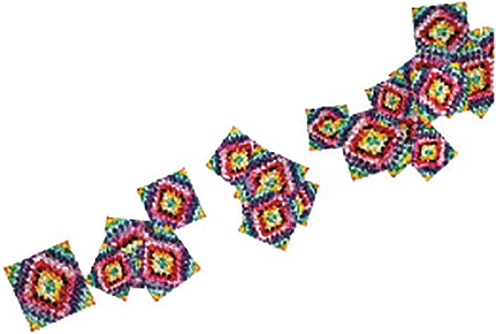
A layers panel indicates the option, Place Along a Path, highlighted.
Create a new layer in the Layers panel for practice and name the layers to keep track of your progress and keep only the new layer visible

A warning message dialog box for Adobe Photoshop indicates that no path is selected.
Warning message reminds you to create a path first before using the script

A pen tool option in path mode indicates the open path is admissible. A path option with a drop-down menu, make, mask, shape, and auto add or delete.
Pen tool options in Path mode

A path fill dialog box indicates the path that was produced using the path tool. The diagram is saved as Path 1.
Path created with the Path tool and a path in the Paths panel
To review that, refer to “Project: Create a Custom Symmetry Paint Path” and the Pen tool sections of this chapter.
Pattern Scale (0.1-1.25): Makes the pattern larger or smaller. Often smaller, less detailed patterns are best for this dialog box to render, or you may get a warning message.
Spacing in pixels (-2660, 0, 7980): Often a small spacing is best, as too high a number makes the space too great and too low a negative number can make the pattern difficult to see. This setting range may vary depending on what pattern was chosen.
Adjust spacing to fit: Click the checkbox to enable
Angle from path in degrees (-90,0,90)
Distance from path in pixels (0-2000): This setting range may vary depending on what pattern was chosen.
Alternate patterns: On the path, click the checkbox to enable. It is enabled by default.
Scale progression percentage (90-110%)
Skip symbol rotation: When this checkbox is enabled, it disables the spacing and angle from the path options parts of the pattern and they will not be rotated.
Color randomness (0-1): Alters the color of the tiles with higher settings.
Brightness randomness (0-1): Alters the brightness of some of the tiles; a setting of 1 makes some tiles black. Refer to Figure 3-174.

A place along dialog box indicates the alternate patterns checked in the preset custom.
Place Along Path dialog box
What you see in the preview may be slightly different than what appears on your custom path and may require you to use your History panel a few times to get the tiles on the path to your liking.
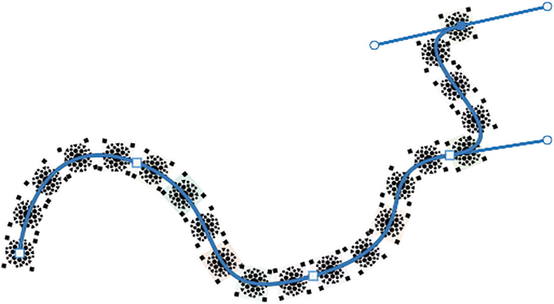
An image depicts the altered pattern such that it fits the scale and spacing of the motif.
Pattern on Path

A paths panel indicates the deselection in the paths. The diagram is saved as Path 1.
Pattern on Path, path deselected in the Paths panel

A layers panel indicates the option, Random Fill, highlighted.
Create a new layer in the Layers panel for practice and name the layers to keep track of your progress and make only that layer visible

A random fill dialog box has parameters under preset custom, density at 10, minimum scale factor at 0.5, maximum scale factor at 1, rotate pattern on, color randomness at 0.21, and brightness randomness at 0.18.
Random Fill dialog box
Density pixels (0.1-10): How many tiles fill the area without leaving gaps
Minimum scale factor (0.1-3): Works with the minimum scale factor to alter the size of the tiles
Maximum scale factor (0.1-3): Works with the minimum scale factor to alter the size of the tiles
Max distance from paths in pixels (0-250): This setting is only available if a path is enabled. See “Place Along a Path Script” earlier for more details on how to create a path. Refer to Figure 3-179.
An image depicts a series of photos forming a slanting curved line.
Pattern on a Path when a path is selected prior to entering the dialog box
Rotate Pattern : When this checkbox is enabled, it causes the pattern to rotate. When disabled, the pattern can be at random sizes but are now square. Refer to Figure 3-180.

An image depicts the repeating pattern that will be rotated.
Rotate Pattern disabled for random fill
Color randomness (0-1): Alters the color of the tiles with higher settings.
Brightness randomness (0-1): Alters the brightness of some of the tiles; a setting of 1 makes some tiles black.

A series of photographs on top of each other depict the density, minimum and maximum scale factors, enabling rotate pattern.
Random fill pattern generated

A layers panel indicates the option, Spiral, highlighted.
Create a new layer in the Layers panel for practice and name the layers to keep track of your progress and make only that layer visible

A spiral script dialog box has parameters under preset custom, pattern scale at 0.97, ring spacing at 147, pattern spacing at negative 27, color randomness at 0.12, and brightness randomness at 0.21.
Spiral script dialog box
Pattern Scale (0.1-1.25): Alters the size the pattern tiles collectively.
Ring spacing in pixels (-708, 0, 1656): Depending on the pattern, this setting may make little difference to the spacing of the spiral. Spacing range may vary due to what image is chosen.
Pattern spacing in pixels (-708, 0, 828): Bring the spacing either closer together or farther apart. Spacing range may vary due to what image is chosen.

A series of photographs form a spiral by rotating itself. Another series of photos form a spiral without rotating itself.
Keep Pattern Upright disabled and enabled
Keep Pattern Upright: When this checkbox is enabled, the pattern does not rotate with the spiral. Refer to Figure 3-184.
Color randomness (0-1): Alters the color of the tiles with higher settings.
Brightness randomness (0-1): Alters the brightness of some of the tiles; a setting of 1 makes some tiles black.

An image of the spiral fill pattern generated is observed.
Spiral fill pattern generated

A layers panel indicates the option, Symmetry Fill, highlighted.
Create a new layer in the Layers panel for practice and name the layers to keep track of your progress and make only that layer visible

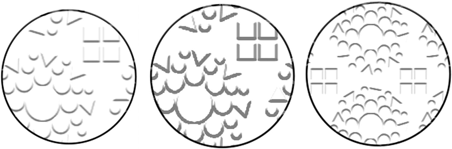
A symmetry fill dialog box has parameters under preset custom, symmetry type, different pattern scales, color randomness at 0.05, and brightness randomness at 0.1.
Symmetry Fill dialog box

A symmetry fill dialog box depicts its list of parameters or options.
Symmetry type options
Take some time to preview each of the symmetry fills on your own and see which ones look best for your pattern. Every one is very different.

A series of photos depict the Droste-like pattern growing within one another and curling inwards like a flower's core.
Symmetry fill pattern number 7 generated
Pattern Scale (0.25-1.25): Alters the size the pattern tiles collectively
Pattern translation along the width percentage of width (-100, 0, 100%): Alters the complexity of the pattern along the width
Pattern translation along the height percentage of height (-100, 0, 100%): Alters the complexity of the pattern along the height
Color randomness (0-1): Alters the color of the tiles with higher settings.
Brightness randomness (0-1): Alters the brightness of some of the tiles a setting of 1 makes some tiles black.
In this example, I used a Pattern scale of 0.9, set the Width translation to 75%, Height translation to 75%, Color randomness of 0.05, and Brightness randomness of 0.1. Refer to Figure 3-187.

A layers panel indicates the option, Symmetry Fill for the Droste-like pattern, highlighted.
Various Fill script layers in the Layers panel
There are limits to how much you can scale these fills. Something you can do to avoid having areas chopped off at the edge is to make your canvas size a bit larger before you fill with a script. Another way that I have found around the resolution issue is to make sure that the file that I am creating the random or symmetry fill in is set to 600ppi. Then, if I must copy the background into a file at 300ppi, I find I can get a larger, better quality graphic if scaling is required.
Adjustment Pattern Fill Layers

A layers panel indicates the option, Symmetry Fill for the Droste-like as a pattern, highlighted.
Create an adjustment layer pattern fill

A pattern fill dialog box where angle is at 0, scale at 100%, and link with layer is active.
Pattern Fill dialog box

A pattern dropdown menu and options where Small Thumbnail is selected.
Pattern dropdown menu and options

A pattern fill dialog box where angle is at 0 highlighted, scale at 100%, and link with layer is active.
Pattern Fill dialog box options for scale and rotation

An image depicts the icon for the move tool that is used to drag to reposition the pattern.
Use the Move tool to move your pattern

A pattern fill adjustment layer is entered to the layers panel.
Enter the Pattern Fill adjustment layer anytime from the Layers panel
These features are non-destructive to the pattern fill , and you can double-click the pattern fill layers thumbnail at any time to enter it and make adjustments.

A layers panel where Pattern Fill 1 is at normal opacity at 12%.
For readability, lower the opacity of your Pattern Fill layer if text is to be over it
We’ll look at text in more detail in Chapter 5.

A pattern fill adjustment layer is entered into the layers panel, where the pattern fill layer mask hides part of the pattern.
Use the Pattern Fill layer mask to hide part of the pattern

A properties panel indicates its parameters. These are masks, layer mask, density at 100%, feather at 0.0, and refine.
Alter the Pattern Fill mask using the Properties panel to set Density and Feather
Later you can apply additional adjustment layers on top of your current pattern fill for additional color enhancement.
Layer Styles with Patterns and Textures

An options panel is active for the shape tools, and the ellipse tool is selected.
Use a Shape tool to create a shape and the Options panel to edit before you add layer styles with patterns and textures

A layers panel indicates the option, Ellipse 1, stroke, highlighted.
From the Layers panel, add a layer style to your vector shape layer
Blending Options
Bevel & Emboss
Stroke
Inner Shadow
Inner Glow
Satin
Color Overlay
Gradient Overlay
Pattern Overlay
Outer Glow
Drop Shadow
Most layer styles rely on a combination of opacities, blending modes, colors, and gradients to get the effect you are looking for. However, there are a few layer styles like Bevel & Emboss, Texture, Stroke, and Pattern Overlay that allow you to reuse your patterns in unique ways.
While you should experiment with all layer styles, let’s focus on where to add the pattern or texture to the three I just mentioned.

A layer style dialog box indicates the different blending options.
From the Layers panel , enter the Layer Style dialog box
While in this area, you can use your Hand tool and Zoom tool key commands of Ctrl/CMD++ or Ctrl/CMD+– if you need to zoom in and out of an area.
Bevel and Emboss – Texture

A layer style dialog box indicates the styles, bevel and emboss, texture are selected. Different C h 3 patterns.
Layer Style options for Bevel & Emboss - Texture
From here, in the elements, you can choose a pattern that becomes an embossed texture. As with other patterns, you can add a new preset pattern to the Patterns panel using the plus icon.

Two images depict the surface pattern that is applied to the object.
Texture applied to shape
Three images depict the modifications made to the scale and depth of the texture.
Texture scale and depth adjustments

A texture setting depicts its parameters. These are elements, pattern, scale, depth, and link with layer is active.
Texture settings

A bevel and emboss setting depicts its parameters. Under structure are style on inner bevel, technique, depth, direction, size, and soften.
Bevel & Emboss settings adjusted for Style
Stroke
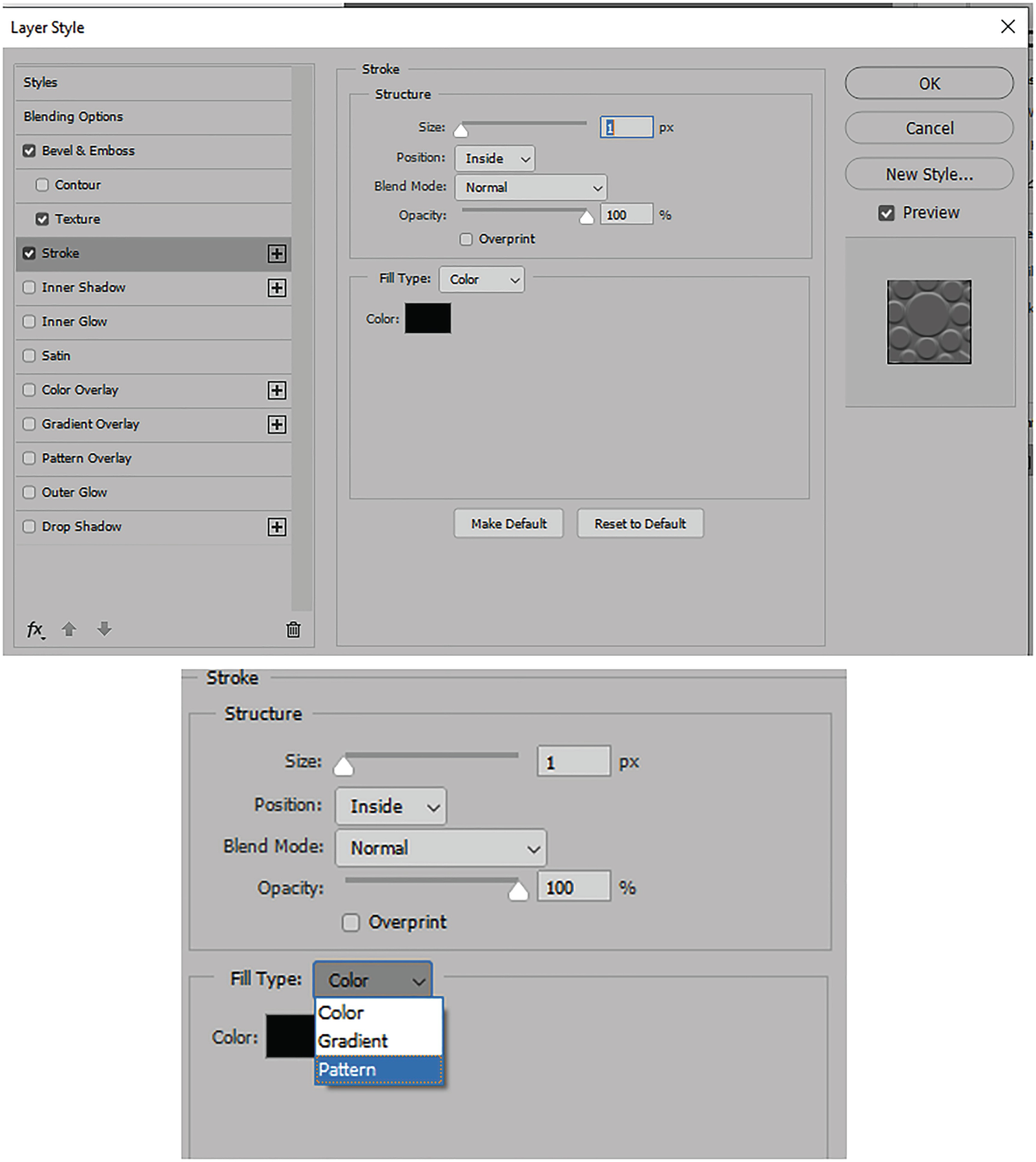
A layer style options for stroke where its structure size is at 1 pixel, position at inside, blend mode at normal, and opacity at 100%.
Layer Style options for Stroke

A layer style options for stroke with pattern indicates the load of a default pattern and then fills type parameters that are associated with it.
Layer Style options for Stroke with Pattern
As with Bevel & Emboss - Texture, you have the same options to change the pattern. Create a new pattern preset. Snap to origin if the pattern is moved, alter the angle, change the scale size, and link with layer so that the pattern moves together with the shape.

A layer style options for stroke with pattern with size at 76 pixels, position at center, blend mode at difference, opacity at 100%, and scale at 100%.
Preview and Layer Style options for Stroke with Pattern

A layer style options for stroke with pattern with different tree pattern selections.
Layer Style options for Stroke with Pattern, changing the pattern to a new pattern

A layer style options for stroke with pattern indicates the addition of more than one stroke with a pattern layered on top of each other.
Preview and Layer Style options for Stroke with Pattern , adding another stroke called Tree Tile 4

A layer style options indicates the deletion of a style from the list.
With two stokes , use the Trash can icon to select one and remove it if required
Pattern Overlay

A layer style options where pattern overlay is active, blend mode is at normal, opacity at 100%, angle at 0, and scale at 129%.
Layer Style options for Pattern Overlay
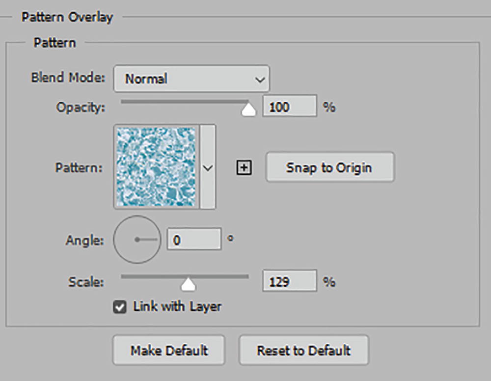
A layer style options for pattern overlay where the parameters are blend mode at normal, opacity at 100%, angle at 0, scale at 129%, and link with layer is active.
Layer Style options for Pattern Overlay

A layer style options for pattern overlay where the parameters are blend mode at normal, opacity at 50%, angle at 0, scale at 129%, and link with layer is active.
Layer Style options for Pattern Overlay , new Pattern and Preview

A layer style options for drop shadow where the parameters are blend mode at multiply, opacity at 35%, angle at 125, distance at 83, spread at 0, and size at 68.
Layer Style options for Drop Shadow and Preview

A styles panel depicts the creation of a new style. Import styles option is selected.
Save your new style and store it in the Styles panel in a group folder and then you can export the style later for others to use
Other layers styles with additional patterns can be found here as well, which you can modify for your project. We’ll talk more about layer styles again in Chapter 5. However, as with the Patterns panel , you can create a group folder to store your styles in and later Save (Export Selected Styles) as an .ASL file that others can Load (Import Styles) and reuse.

A layers style panel depicts the parameters for the vector shape layer. Ellipse 1 is selected.
Layer styles applied to the vector shape layer in the Layers panel
Tools That Use Patterns

A layers panel depicts the process of the creation of a new layer. Layer 1 is selected.
Create a new layer in the Layers panel for practice and name the layers to keep track of your progress
Pattern Stamp Tool (S)
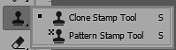
A context menu depicts the icons for the clone stamp tool and pattern stamp tool.
Pattern Stamp tool
Pattern Stamp Tool Options

An options panel for the pattern stamp tool, the pointer size is at 81, mode is at normal, opacity at 100%, flow at 100%, angle at 0, and it is aligned.
Options panel for Pattern Stamp tool

An options panel depicts the different choices for the pattern stamp tool.
Patterns options for Pattern Stamp tool

An image depicts the process of painting with the pattern stamp tool.
Paint with the Pattern Stamp tool with your custom brushes or the Impressionist option
Aligned, when enabled, uses the same offset for each stroke as you lift your brush; that same pattern still remains, and a new pattern does not start. Impressionist, when enabled, has a soft blurry effect and works best with brushes with a lower hardness. The last button icon in the Options panel, Always use Pressure for Size, is affected by the current brush settings. When off, it is controlled by the brush preset. Refer to Figure 3-223 and Figure 3-224.

A layers panel indicates the usage of the color fill mask along with the pattern stamp tool. The color fill 1 is selected.
Paint on a Color Fill mask with the Pattern Stamp tool
You can alter the color fill at any time with the mask pattern applied.
Paint Bucket Tool (G)

A context menu depicts the different icons for gradient tool, paint bucket tool, and 3 D material drop tool. The gradient tool option is selected.
Paint Bucket tool and options in the Options panel currently set to Foreground but choosing the Pattern option
Paint Bucket Tool Options

An options panel for paint bucket tool, mode at normal, opacity at 100%, tolerance at 32, anti alias, and contiguous are active.
Options panel for Paint Bucket tool now set to the Pattern option

A layers panel depicts the water pattern options for the paint bucket tool.
Pattern options for Paint Bucket tool

An options panel for fill blend mode ranges from normal, dissolve, behind, and clear. Normal option is selected.
Fill Blend Mode options for Paint Bucket tool
Set your Opacity (1-100%), Tolerance or Range of colors to fill (0-255), enable Anti-alias for a smoother blend and Contiguous for filling touching pixels. All Layers, when enabled, will affect how the paint bucket fills on the current layer; leave this setting unchecked. Refer to Figure 3-229.

Two rectangular marquees, one is filled with a pattern from the paint bucket tool, and the other is empty.
Rectangular Marquee options and selection filled with a pattern from the Paint Bucket tool
Select the Paint Bucket tool and click inside the selection to fill with your chosen pattern. Otherwise, it will fill the whole layer.

A context menu has the option, Deselect, highlighted.
Deselect the selection after you fill it with pattern

A layers panel indicates the application of a mask using the paint bucket tool while working on a color fill layer.
Use the Paint Bucket tool on a mask on a Color Fill layer
Healing Brush Tool (J)

A context menu depicts the icons for spot healing brush tool, healing brush tool, patch tool, content-aware move tool, and red eye tool.
Healing Brush tool

Two options panel for healing brush tool parameters. These are at normal mode, sampled or pattern, angle at 0, and diffusion at 5.
Options panel for Healing Brush tool set to Sampled and Pattern
Healing Brush Tool Options
Look at the Options panel from left to right. Like the Brush tool , after the tool preset area, you can set your Brush Preset Picker options of size, hardness, spacing, angle, and roundness. Refer to Figure 3-234.

A clone source panel where the parameters are frame offset, show overlay active, opacity, and clipped active.
Clone Source panel

A blending mode menu has the option, Normal, highlighted.
Options panel for Healing Brush tool’s Painting Blending modes
Unlike the other blending modes, Replace is used to preserve noise, film grain, and texture at the edges of the brush stroke when using a soft-edge brush and you will not have access to the Options panel’s diffusion settings. Refer to Figure 3-236 and Figure 3-237.

Two options panel for healing brush tool parameters reversed from sampled to pattern. The sample is set to current and below.
Options panel for Healing Brush tool switched from Sampled to Pattern
Aligned, when enabled, allows you to align the same offset for each stroke.
The Use Legacy setting is from an older Photoshop version (CC2014). This option will also disable the Diffusion option.
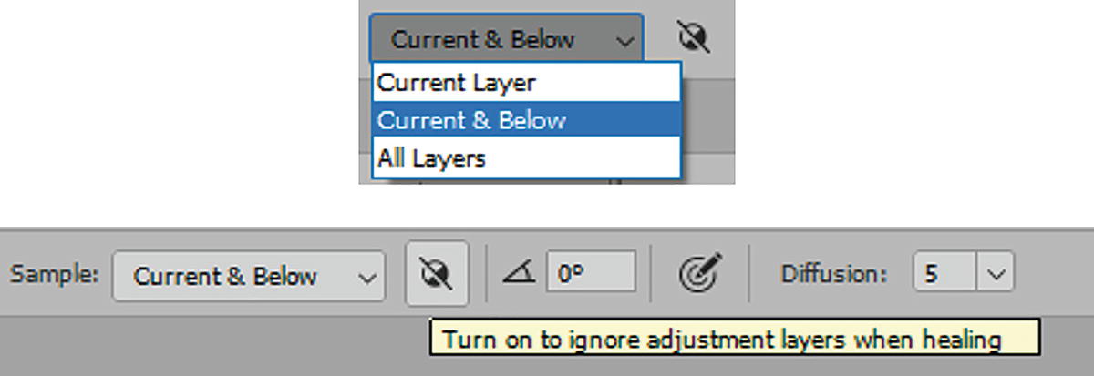
A context menu has the option current and below is highlighted. Another options panel for healing brush tool parameters indicates to turn on to ignore adjustments layers when healing.
Options panel for Healing Brush tool Sample options
The next section allows you to set the brush angle, which is the same as what is set in the Brush Preset Picker . The next button is Always use Pressure for Size or let the brush preset control the pressure. And a Diffusion (1-7) slider. This slider and number controls how quickly the pasted region adapts to the surrounding image. Adobe recommends you select a lower value for images with grain or fine details and a higher value for smooth images.
Depending on the choice of brush, blending mode, or pattern, this can create some unusual blur and pattern effects.
I made a copy of my Symmetry Fill layer (drag over the Create new layer icon in the Layers panel) and then tested the tool on it with a pattern.
While in Pattern source, you do not need to Alt/Option+Click to retrieve a sample for the heal; simply paint with your brush and create a pattern covering.
I recommend working on a new layer when using this tool, so that you can later fade the layer’s opacity or alter its blending mode as required.

A layers panel indicates the usage of the healing brush on a copy of the symmetry fill layer and a patterned color fill mask beneath.
Painting with the healing brush on a copy of the symmetry fill layer and a patterned color fill mask behind
For more detail on healing brush topics, you can refer to these links: https://helpx.adobe.com/photoshop/using/retouching-repairing-images.html and https://helpx.adobe.com/photoshop/using/healing-examples.html .
Patch Tool (J)

An options panel for patch tool parameters reversed from normal to content aware.
Options panel for the Patch tool set from Content-Aware to Normal Patch mode
Patch Tool Options

An image depicts the tool's loop dragging the new selection option.
Create a selection
Add to selection (Shift+Drag)
Subtract from selection (Alt/Option+Drag)
Intersect with selection selections (Alt/Option +Shift+Drag)

Images depict the procedure of using the selection as a source when moving it.
Move the selection as a source

Images depict the operation of moving the selection to a different destination.
Move the selection as a destination

An image depicts two icons for the transparent option enabled and disabled.
Transparent option enabled and disabled

An options panel for the patch tool depicts the different choices for a design pattern.
Options panel for the Patch tool . Click the Use Pattern button to add the pattern to the patch
In the last section, as with the Healing Brush tool, you can also set the degree of diffusion from 1-7. See the Healing Brush tool for more details on this option. Refer to Figure 3-245.
Click elsewhere on the canvas to remove the selection, or Select ➤ Deselect, or Ctrl/CMD+D.

A layers panel depicts the use of the symmetry fill patch tool.
Edited layer using the Patch tool

An options panel for the patch tool where patch is at content aware, structure at 4, and color at 0.
Options panel for the Patch tool in Content-Aware mode
For details on content-aware features, you can check out in this link (it also applies to the spot healing brush and content-aware move tools): https://helpx.adobe.com/photoshop/using/content-aware-patch-move.html .
Make sure to File ➤ Save your document at this point.
Project: Create a Texture for the Filter Gallery
While custom patterns and textures seem interchangeable when it comes to layer styles and some healing tools, this is not the case when it comes to filters, as you will see in Chapter 8 when you work in the filter gallery . In this gallery, you will not have access to the Patterns panel and must instead create a file to load a texture.

An image depicts the pattern of cross stitching that is utilized to add texture.
Cross-stitch pattern to be used for texture

Dialog box 1 is for flatten the image before mode change and dialog box 2 is for discard color information.
Warning message when changing a file from RGB color mode to grayscale

An image depicts a grayscale pattern of cross stitching that is utilized to add texture.
Grayscale pattern

An image depicts a grayscale pattern of cross-stitching that is utilized to add texture and the usage of a crop tool.
Grayscale pattern cropped using the Crop tool and its Options panel

Multiple images depict a grayscale pattern of cross stitching that is utilized to add texture.
Testing the texture pattern in Pattern Preview
The texture now looks good. Click View ➤ Pattern Preview again and click the Move tool to exit the Crop tool.
Make sure to File ➤ Save this as a .psd file such as Pattern4_Texture.psd. You can find my example in the folder Cloth_Patterns. Keep it aside in your project folder for now. In Chapter 8, we’ll look at this custom texture again and how to load it and test whether it is seamless.
You can also use Patterns found in the Patterns panel and in the Layers, panel rasterize the Pattern Fill adjustment layer when you right-click on it and from the pop-up men choose Rasterize Layer and then repeat this project to re-use those patterns as a texture.
In this current version of Photoshop, you can also create additional patterns using the new Window ➤ Materials panel for Substance Materials which you can learn more about here:
https://helpx.adobe.com/photoshop/using/substance-3d-materials-for-photoshop.html
Folders containing Brushes (.abr), Library files (.cclibs), Patterns (.pat), Shapes (.csh) and Layer Styles (.asl) used in this Chapter can be found in the Chapter’s folder and you can import them using that panels menu.
Summary
In this chapter, you looked at the many ways to create patterns and use them with other tools such as the Pen and Shape tools and then dialog boxes, the Offset filter , and the Layers panel. While working with patterns can involve many tools, in the next chapter you will look at a collection of editing tools that affect the transformation of an object on a layer, either in a destructive or non-destructive way, depending on the type of layer that is used.