Chapter Goal: In this chapter we will continue to explore various advanced filters found in the Filter menu.
For warping and distorting, we will look at Vanishing Point and how it compares to Perspective Warp. We’ll also look at two of the latest Neural Filters. Later I will mention how you can acquire additional filters.
You can find the projects for this chapter in the Chapter 10 folder.
Advanced Filters

A 4-section menu exhibits a highlighted vanishing point filter. It can be accessed via a combination of Alt + C t r l + V on the keyboard.
Advanced filters in the Filter menu
Vanishing Point
The Vanishing Point filter is very similar to the Perspective Warp tool in Chapter 7 but does have some important differences that I will point out. This filter does not work with smart object layers. However, you can have smart object layers within the file. In this case, we will be working with several normal layers, as I will be demonstrating in this section of the Chapter.
For this project, you can use your own files or you can follow along with me and use the files in the projects folder.
Project 1: Using the Vanishing Point Filter to Alter a Road Area and Place Graffiti Graphics on a Fence
File ➤ Open vanishing_point_paint_stamp_start.psd. Like the other projects we’ve worked in so far, it is in RGB Mode so that I can use this filter.

A pop-up window labeled duplicate image exhibits a highlighted field entry that reads vanishing point paint stamp start copy.
Duplicate Image dialog box

A photograph of a bike lane with a tall wooden fence on the right side under a bright sky.
A road with a long fence moving into the distance on the left
I do not condone destroying or altering other people’s property. You should only be painting your artwork or murals on other people’s walls or fences after you have received permission from the owner or business. However, in the virtual world of Photoshop, you can be as artistic as you want, and nobody will be upset.
The Vanishing Point filter is probably one of the most complex filters to master in Photoshop, and to a beginner or intermediate student of the program it can appear a bit confusing. However, I am going to show you some simple ways that you can use this filter if you have a concept image design that requires artwork or signage to be added to a wall digitally before you add it to a wall in reality.
Adding artwork to a wall that you are looking at directly at it is easy. But if you are given a picture by a client where the wall, building, or ground are at an angle or certain perspective, it’s quite a challenge.
Remember, perspective is the art of drawing solid objects on a two-dimensional surface so as to give the right impression of their height, width, depth, and position in relation to each other when viewed from a particular point.
In Chapter 4, we figured that out manually by just using Edit ➤ Transform ➤ Perspective or Warp, solely using the bounding box handles on a layer in the Layers panel. But that is not always the best solution. We found a better way in Chapter 7 using Edit ➤ Perspective Warp, which gave better results and could be stored as a smart object layer. To become a Photoshop artist, your eyes need to be trained to recognize the correct perspective.
We will review Perspective Warp in the third part of this project.
Thankfully, Photoshop makes it very easy to learn with the Vanishing Point tool. And you can create perspective in a less destructive way when you follow the filter’s rules.
If you are using your own background images in this project, you may need to Edit ➤ Transform ➤ Rotate or even use the Filter ➤ Adaptive Wide Lens and use guides if you need make the scene level before you proceed, as this could affect how the filter interprets the perspective planes. In my images that you are using, I have already adjusted for that.
For this filter, as well as the others, I am working with a file format .psd which, as you have seen, can have multiple layers. This is best because you will be working over more than one photo layer to create the vanishing point perspective.

A pop-up window labeled layers exhibit the 2 rows of layer 1 and the background next to their respective image. The icon to create a new layer is selected.
Always work on a blank layer in your Layers panel when using the Vanishing Point filter
Go to Filter ➤ Vanishing Point filter (Alt/Option+Ctrl/CMD+V). The workspace will open, and you will be presented with some tools on the left-hand side and options for each tool will appear above the preview image.

A window labeled vanishing point and a list of options on the left panel and a photo of a bike lane next to a fenced area on the main panel.
The Vanishing Point filter workspace
As well, I will be mentioning some keyboard shortcuts throughout the project that should be used within the filter .
Vanishing Point Workspace

Three cropped images of the available options from the vanishing point window. Some of the options are to zoom, change the grid size, and show edges.
Vanishing Point filter Tool Options panel and menu for settings and commands
From the drop-down menu of Settings and Commands for the Vanishing Point, we will not be looking at any 3D files (DFX, 3DS, After Effects (.vpe)). Also, we will not look at render measurements for import or export to 3D programs using this filter because that is an advanced topic that is not relevant to this chapter. If you need information from Adobe on this topic and how 3D in new versions is moving to the Substance Collection, refer to this link: https://helpx.adobe.com/photoshop/using/vanishing-point.html
(see in link “Work in Vanishing Point Export measurements, textures, and 3D information”).
However, make sure that Show Edges and Show Measurements are checked in this menu. Refer to Figure 10-6.
Vanishing Point Tools and Options
Edit Plane tool (V): Selects , edits, moves, and resize planes. First, a plane must be drawn using the Create Plane tool before you can use this tool to move the plane. It is very much like a combination of the Move tool and Path Selection tool outside of this dialog box. Here you can set the Grid Size of the plane (1-1000) as well as the Angle (0-360) of additional planes when added. Refer to Figure 10-7.
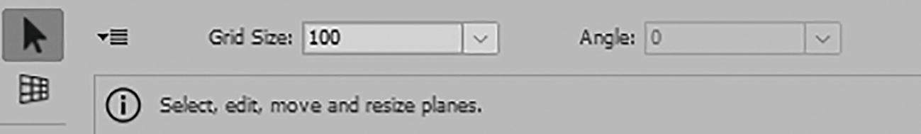
An options panel exhibits a highlighted arrow icon representing the edit plane tool. Grid size and angles can be set to accommodate user needs.
Edit Plane tool and its Options panel
Create Plane tool (C): Defines the four corner nodes of a plane in blue when placement is correct, but when incorrect it appears as yellow with a grid or red with no grid. Refer to Figure 10-8.

An options panel exhibits a highlighted angled window icon representing the create plane tool. Below are 3 photographs of the wooden fence with differently colored line patterns.
Create Plane tool and its Options panel with different colored grids on the fence

A photograph of the wooden fence with line patterns extending to the curb. Above is an icon of a 4-section box with an angled arrow on the upper left.
Tear off additional planes with the Edit Plane tool

A zoomed section of the options from the vanishing point window with a selected edit plane tool, grid size set to 100, and angle set to 270.
The Edit Plane tool can adjust the angle for the tear off plane

A zoomed portion of the drop-down menu in the vanishing point window. From here, the show edges and show measurements options are checked.
Menu option settings
Marquee tool (M): Makes square or rectangular selections that can be filled and allow you to move or clone selections. Refer to Figure 10-12.

An image of a dashed rectangular icon representing the marquee tool. Below are the dedicated panel's feather, opacity, heal, and move mode options.
Marquee tool and its Options panel
For the Move Mode dropdown menu, to use Destination and then Source, the Info panel says that you can Click+Drag in a plane to select an area on that plane or create a marquee selection.

A photograph of the wooden fence with a highlighted post. On its right is a drop-down menu depicting a highlighted destination option under move mode.
Alter the Move mode of the selection marquee
Once the selection is in in place, you can Alt/Option+Drag the selection to copy the area to a new destination.

A photograph of the wooden fence with a highlighted post as copied from a wider photograph. Between the two is an overlapping arrowheads icon.
Make a copy of you selection and move it to a new destination

A set of before-and-after photographs of the cloning process done on the highlighted post of the wooden fence. The source is selected from the move mode drop-down menu.
Clone the area within your selection from a new source
A selection can span more than one plane. All selections can be scaled, rotated, or transformed while using the Transform tool, which we will look at shortly.
Adobe mentions that items from one Vanishing Point dialog box can be copied to another while opening, then closing, and opening the other document and pasting again into the vanishing point preview.
The other options for the Marquee tool include Feather (0-50), which will blur the selection and set the feather to the edge.

A zoomed section of the options panel for the marquee tool exhibits a feather option set to 1 and an opacity option set to 100.
Marquee tool and its Options panel settings for Feather and Opacity

Two drop-down menus for move mode and heal with highlighted source and off options. Below are 4 photographs of the process of covering up the bike lane sign on the road.
Marquee tool and its options panel settings for Move mode with the Heal options of Off, Luminance, and On
The Heal options apply to the Brush tool and Stamp tool as well.
Stamp tool (S): Paints with a sample of the image. Unfortunately, unlike the Clone Stamp tools, outside of the dialog box, it can`t clone elements from another image externally, only the current image inside the preview area. Refer to Figure 10-18.

An image of a stamp icon representing the stamp tool. Below are the options- diameter, hardness, opacity, heal, and aligned options in its dedicated panel.
Stamp tool and its Options panel

A set of wide and zoomed shots of the selected area on the road where a fading bike line sign is observed.
Using the Stamp tool on the ground plane to clone over the bike logo
Shift+Click to extend the stroke to the last click. To make a better blend, you can change the brush’s Diameter (1-500), Hardness (0-100), Opacity (0-100), and Heal options (Off, Luminance, On) as you paint. Check Aligned to keep the brush source in sync with the destination. Refer to Figure 10-18.
The plane outline turns green when using this tool. Refer to Figure 10-19.

A photograph of one of the panels of the wooden fence with a digital painting of the word Hi. An angled brush icon for the brush tool is on the lower left.
Use the Brush tool to paint within a plane
Brush tool (B): Paints a selected brush color on a plane using Click or Click+Drag as you would with any paint brush. Shift+Click to extend the stroke to the last click. Ctrl/CMD+Click in another plane to paint there instead. You can even paint outside the plane. Refer to Figure 10-20.
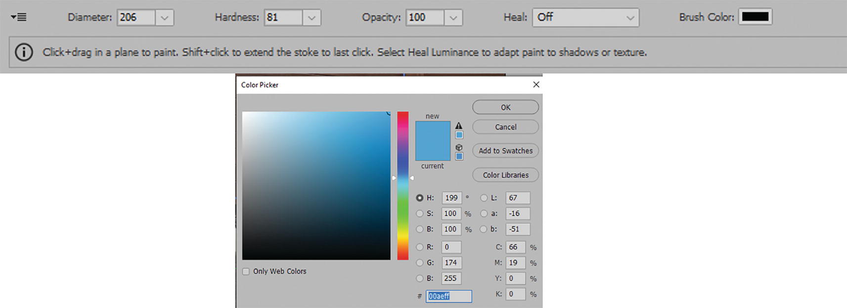
An options panel exhibits the diameter, hardness, opacity, heal, and brush color options for the brush tool. Below is a pop-up window labeled color picker with a wide range of colors to choose from.
Brush tool and its options panel and the Color Picker dialog box
You can change the brush color by clicking on the swatch and entering the Color Picker. Click OK to exit once you have selected a new color.
Once out of filter`s workspace, you can continue to do color adjustments with the layer’s blending modes, which we will look at later in this project.

A photograph of the bike lane sign on the road that is selected from the original just above it. An icon of a rectangle with an arrowhead is depicted.
Use the Transform tool to scale and rotate a selection

An options panel exhibits flip and flop checkboxes for the transform tool. On its right are descending images of the bike lane sign that is rotated via flip, flop, and flip and flop.
Transform tool and its options panel with settings used on a selection for flip and flop
Eyedropper tool (I): Click to select a color for the Brush tool for painting from the preview image. Click the color swatch to open the Color Picker and choose a color. Refer to Figure 10-24.

An image of an angled dropper icon for the eyedropper tool. Below is the brush color as the lone option in its panel.
Eyedropper tool and its Options panel
Measure tool (R): Click two points to measure an angle and a distance or length (1-999). Edit the distance to set the scale for measurement. If you can’t see the measurements, make sure Show Measurements in the dropdown menu of Commands and Settings is enabled. You can enable Link Measurement to Grid to link the measurement units with the grid size. Refer to Figure 10-25.
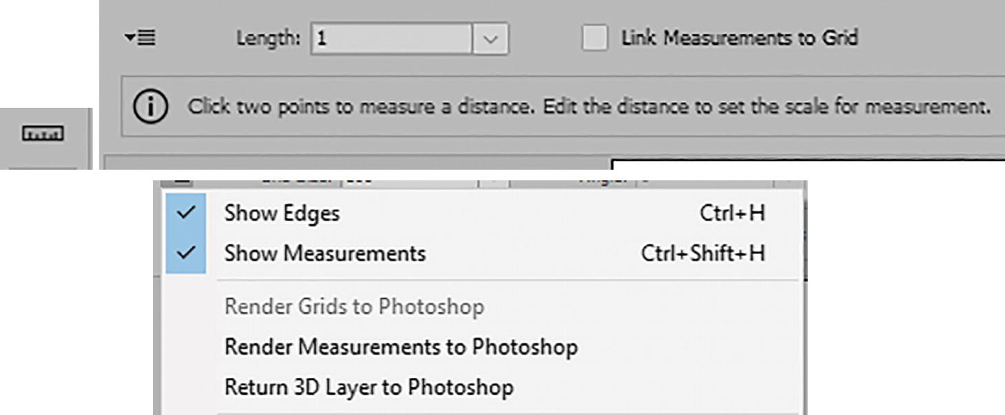
An options panel for the measurement tool, represented by a horizontally oriented ruler on the lower left, exhibits length and links measurements to grid options. Below are checked show edges and show measurements from the drop-down menu.
Measure tool and its Options panel with additional menu options
Hand tool (H): Move the image in the Preview window via Click+Drag with the mouse. Holding down the spacebar key while using another tool will change the cursor to the Hand tool. This tool allows you to move about the Preview image without disturbing the planes. Refer to Figure 10-26.

An options panel for the hand tool, represented by a raised hand on the lower left, exhibits a text box that reads click plus drag, to scroll the image in the preview window.
Hand tool and Options panel info
Zoom tool (Z): Magnifies the image in Preview. Click to zoom in and Alt/Option-Click to zoom out. Click+Drag will allow you to zoom in on an area. Ctrl/CMD++Ctrl/CMD+- and Ctrl/CMD+0 to zoom in and out will also work. Or just use the Navigation area at the bottom of the screen. Refer to Figure 10-27.

An image of an angled magnifying glass icon for the zoom tool. In its panel is a text box with a click, alt plus click, and click plus drag commands, while 33.3 percent is displayed on the zoom navigation area.
Zoom tool and Options panel info with zoom navigation in the lower left of the workspace
If you would like to review a few more keyboard shortcuts, go to https://helpx.adobe.com/photoshop/using/default-keyboard-shortcuts.html#keys_for_vanishing_point .

Two capsule-shaped buttons labeled O K and cancel.
Click OK or Cancel to exit the workspace
However, for now, let`s stay in dialog box for this image and use some of the tools.
Creating and Editing Planes with Vanishing Point Tools

An image of an angled window icon for the create plane tool. Below is a photograph of the wooden fence with line patterns on about six of its panels.
Create a plane for the fence using the Create Plane tool

An image of an angled arrow representing the edit plane tool.
Edit your plane using the Edit Plane tool
Zooming in or out with the Zoom tool may also help you when working with the plane. The filter will guide you as the grid plane changes color. As mentioned, when it is blue, the perspective is normal or valid. However, you still need to make sure that the grid lines up with your wall or ground to get an accurate perspective. If the nodes are placed incorrectly, the bounding box and grid will turn either red or yellow. This means you need to move the nodes around until they are blue.

An image of an angled window icon for the create plane tool. Below is a photograph of a section of the bike lane with line patterns.
Create another plane on the ground using the Create Plane tool

A photograph of the bike lane with line patterns reaching up to the side of the curb. An angled arrow and a 4-section box with an angled arrow on the upper left icons are depicted.
You can tear off a second plane using the Edit Plane tool with Ctrl/CMD+Drag when the mouse pointer changes to an arrow with a plane grid
To delete the selected the plane , click on it with the Edit Plane tool and then click with the Backspace/Delete key on the keyboard. Or you can Ctrl/CMD+Z to undo these steps and then use the Edit Plane tool to reselect the nodes and readjust the plane.

A photograph of the wooden fence with line patterns on about six of its panels. An image of an angled arrow icon for the edit plane tool is on the lower left.
Use your Edit Plane tool to select the plane you want to edit

An image of an angled brush icon for the brush tool. Diameter is at 150, hardness at 81, opacity at 100, heal is off, and brush color is red in its options panel.
Use the Brush tool and its Options panel to set your settings and then paint on the Preview
I can paint with any brush color and the graffiti design will appear in perspective.

A photograph of a section of the wooden fence with the digitally painted word Hello and an exclamation point next to it.
Painting in perspective on the fence with red and cyan paint
As you can see, the brush does have its limitations as it can only be round. In the second half of Project 2, I will show you a way to add improved graffiti artwork to this wall. To undo basic painting mistakes, use the keyboard shortcut Ctrl/CMD+Z because there is no Eraser tool option with this filter. Just another good reason to work on a blank layer!

An image of an angled arrow icon for the edit plane tool. Below is a photograph of a section of the bike lane, with a view of the signage, with line patterns.
Select the ground plane with the Edit Plane tool

An image of a stamp icon for the stamp tool. The diameter is at 310, hardness is at 50, opacity is at 100, the heal option is off, and alignment is checked in its options panel.
Use the Stamp tool and its Options panel to set your settings before you start to clone

A photograph of a section of the bike lane with a view of the signage. The area near the rear wheel has some level of fade and is near a drawn plus sign.
Set a clone source and then begin to paint
A photograph of a section of the bike lane with nonexistent signage.
Cover the bike logo so that you can no longer see it on the ground
You can also use Ctrl/CMD+Z to undo steps. As mentioned, you can use this Clone Stamp tool outside of the Vanishing Point workspace, but the perspective might not be as accurate.

An image of an angled arrow icon for the edit plane tool. Below is a photograph of a wooden fence with digitally painted text Hello exclamation point and line patterns.
Select the fence plane with the Edit Plane tool

A photograph of cloning a highlighted post that results in creating another post in the middle of the wooden fence. On the lower left is a dashed rectangular icon for the marquee tool.
Use the Marquee tool to create a rectangular marquee and make a copy of the fence board that you can drag to a new location further to the right
These selections can be used in multi-surface operations where a tear off plane might extend onto the curb.

A photograph of the cloned post in the wooden fence.
Deselect the marquee selection and then the new board is in place
Afterwards, you might want to use the Stamp tool again to clean the selection up and make the fence boards blend in. Either way, if you are working on top of a blank layer, you are not destroying the background layer below.
The graphic will be clipped off near the selection and plane surface edges. So, in your own project, if you wanted the lower half of the post, you would have to adjust the plane before doing a copy/paste.

A photograph of a section of the fence with digitally painted hello exclamation point text between the 7 highlighted panels. The O K and cancel buttons are on the lower right.
Once you are finished editing in the Vanishing Point filter, you can click OK to exit

An image of two layers labeled layer 1 and background. The digitally painted text and cloned post and surface areas are observed in the former.
The edits created in the Vanishing Point filter are now on Layer 1

A photograph of a section of the wooden fence behind a digitally painted hello exclamation text within a dashed rectangular marquee tool.
Use your Rectangular Marquee tool in Photoshop when you want to copy and paste a selection outside of the Vanishing Point filter to another layer

A pop-up window labeled layers exhibits a highlighted, darken-blended layer 2 above layer 1 and background. The photograph below exhibits the result.
Change the blending mode of your Layer 2 to Darken so that the letters blend in with the wood
If you zoom in with the Zoom tool , you can see some of the wood showing through. Layer blending modes like Multiply, Darker Color, or Lighten are all good to use, but you can try any one of the options in this dropdown menu. Refer to Chapter 2 for more details.
It’s important to experiment, and the blending mode you use depends on your project and what you are trying to blend.

Two pop-up windows labeled layers with highlighted layer 1 before and after adding a layer mask. The photograph below is of a more natural-looking post.
Use a layer mask when you want to edit your fence board using the default colors (D) in the Tools panel and the Eraser tool on the mask

A photograph of the signage-ridden bike lane and digitally painted wooden fence, with darker hello exclamation point text, under a bright sky.
How my artwork currently appears on the fence and the covered bike logo on the ground
So set this part of the project aside for now. You’ll return to it once you understand how to add better graphics to the Vanishing Point filter, which you will see in the second part of the project. File ➤ Save your work as a .psd file. You can see my file, vanishing_point_paint_stamp_final.psd.
Project 2: Adding Graphics to Walls, Roads, and Fences

A photograph of the long, clear wall of a tall building. On the right is a pop-up window labeled layers with a highlighted layer 1 among other layers.
A blank wall and road leading to a loading zone and a blank layer selected in the Layers panel
I have layer named wall and road and some signage in a layer called Vector Smart Object Sign that I created in Adobe Illustrator. The original file is found in the project folder named signage.ai.

A pop-up window labeled paste exhibits a selected smart object among the 5 choices to choose from. On the right is an image of a sign with the text loading zone above a rightward arrow.
This layer for the sign was pasted from Illustrator into Photoshop as a smart object
However, if we want to use this artwork in the Vanishing Point filter workspace, we must select the layer and right-click and choose Rasterize Layer.

A pop-up window labeled Layers has a layer of a highlighted copy of the vector smart object sign. Both feature identical loading zone signage.
Make a copy of your smart object layer
Turn the visibility eye off on original smart object layer to hide it.

A zoomed section of the layers-labeled pop-up window highlights the vector smart object sign copy layer next to a highlighted rasterize layer option.
Rasterize the copy of your smart object layer
Type and shape layers must also be rasterized (rasterize type) if your intent is to use them in the Vanishing Point filter workspace.
We’ll look at an example of type later when we return to the graffiti on the fence in this project.

A photograph of the wall of the building with a superimposed loading zone sign. All and copy options from the edit and select tabs are highlighted.
Select the whole layer for the sign and then copy to the computer’s clipboard
Choosing to select using Ctrl/CMD when you click the layer’s thumbnail icon and then Ctrl/CMD+C won’t work and the shape will not copy. So always use Select ➤ All before you Edit ➤ Copy.

A zoomed section of the layers-labeled pop-up window exhibits a highlighted blank layer 1 above a layer of vector smart object sign copy.
Make sure you are on your blank layer and that your graphic sign layer is turned off
For your own projects, before you enter the Vanishing point filter again, make sure that you always work on a new blank layer so as not to destroy the original, because there is no eraser in the Vanishing Point filter. You do not want to destroy your layer containing the signage if you make a mistake.
Go to Filter ➤ Vanishing Point.

A photograph of a side of the building where its long, clear wall and adjacent road are covered with line patterns. The edit plane tool icon is on the lower left.
Vanishing Point filter: Use the planes that were created earlier for you with the Edit Plane tool
For your own projects, you would have to draw them out yourself. You can review how we did that in Project 1. Remember to draw out your first plane the wall with your Create Plane tool. Click to create the four points. You may need to adjust if the plane is not blue. I created a plane for the road as well, but you do not need this now.

A photograph of the wall of the building with more than half of it highlighted. On the top right is the image of the loading zone sign and on the lower left is the marquee tool icon.
Paste the loading zone graphic into the Vanishing Point filter as a floating selection

A photograph of the highlighted section of the wall of the building with only the zone text from the superimposed loading zone sign visible.
Drag onto the wall plane

A set of wide and close-up shots of the properly scaled loading zone sign on the highlighted section of the wall. The transform tool icon is depicted.
Use the Transform tool to scale the loading zone sign
Use the handles for scaling. Holding down the Alt/Option Key while dragging on the handles will make the sign smaller. Refer to Figure 10-58.
Scaling is important if the graphic comes in larger than the plane area and you don’t want areas of the design to be missing.
Holding down the Shift key while dragging will also allow the scale to be more proportionate with the wall. However, scale to the size you think is correct.

A photograph of the deselected loading zone sign on the highlighted section on the wall of the building. The edit plane tool is depicted.
Deselect the sign while using the Edit Plane tool

Two capsule-shaped buttons labeled O K and cancel.
Click OK to confirm changes and exit the Vanishing Point filter workspace

An image of highlighted layer labeled layer 1. The loading zone sign is observed on the right side of the transparency grid.
The graphic now appears on Layer 1
Select ➤ Deselect (Ctrl/CMD+D) if your layer still has the full marching ants selection on.

A pop-up window labeled layers has a highlighted layer 1 set to a darker color. The photograph on the right exhibits notable blending of the loading zone sign on the wall.
Change the Blending Mode of Layer 1 to Darker Color
As in a previous project, using a layer mask you can as erase with the Eraser tool any areas you don’t want visible.
Now File ➤ Save your work as a .psd. You can refer to my file vanishing_point_image_final.psd at this point.
Adding More Graphics to the Road and Wall
Open the file in the projects folder called vanishing_point_image_final_2.psd. As you can see, I added a few more graphics to my file on separate layers in group folders. One is an arrow on the road and another is a gear logo on the wall.

An image of the logo and arrow example folders. The photograph below exhibits the addition of an arrow on the road and multicolored gears on the wall.
You can add graphics to other blank layers for the wall and road
First, I will explain how that was done here with the arrow and then the gear logo.

An image of an upward arrow icon on the road. On its right are highlighted rasterize layer from vector smart object copy and selected create a new layer option.
Rasterize the graphic of the arrow first if you want to use it for the road

A zoomed section of the layers-labeled pop-up window exhibits a highlighted blank layer 2 above a blank layer of vector smart object copy.
Select a blank layer before you enter the Vanishing Point filter

A set of two images of the upward arrow icon as a floating selection before and after it is pasted and scaled to be wider on the road.
Paste as a floating selection and then drag onto the road plane to start scaling the arrow

An image of the slightly-angled-to-the-right upward arrow icon on the road via the transform tool. The tool's icon is depicted on the lower left.
Use the Transform Tool to scale and rotate the arrow
An image of the edit plane tool icon. On the right are two capsule-shaped buttons labeled O K and cancel.
Select the Edit Plane tool and deselect the arrow before clicking OK to exit the Vanishing Point workspace

A Venn diagram of multicolored gears. On the right is an image of a highlighted blank layer 3 above raster art in the logo folder.
Add another logo to the wall on a blank layer

An image of multicolored gears as a floating selection. The photograph on the right exhibits the logo next to the loading zone sign on the wall.
Paste the logo into the Vanishing Point filter as a floating selection and drag it onto the wall plane

An image of the edit plane tool icon. Two capsule-shaped buttons labeled O K and cancel are on the right.
Select the Edit Plane tool and deselect the logo before clicking OK to exit the Vanishing Point workspace
Made sure to Select ➤ Deselect (Ctrl/CMD+D) any active selection.

A photograph of the wall of the building with multicolored gears below the vent. The move tool icon is depicted.
In Photoshop, use the Move tool to move the logo to a new location

A pop-up window labeled layers has a lighten-blended highlighted layer 2. The photograph below is of the blending between the arrow icon and the road.
Alter the layer blending mode and opacity in the layers panel to blend the arrow into the road

A pop-up window labeled layers has a highlighted layer 3 set to multiply. The photograph on the right is of a less saturated gears logo blending with the wall.
Alter the layer blending mode in the Layers panel to blend the gear into the road
Now you can see some of the road or wall through the graphics. There are many possibilities when it comes to using the Vanishing Point filter. These same ideas can be applied to interior walls and floors of buildings as well.
Finishing Project 1: Adding Graffiti to the Fence
Now that you have seen these ideas, let’s return to Project 1 to add some improved graffiti artwork.

An image of graffiti artwork that reads graphic artist. On the right is a pop-up window labeled layers with a highlighted brush design among others.
Creating graffiti and the layers used in the Layers panel
This layer is a composite of various brush stokes, smudging, selections, and the font Matura MT Script Capitals - Regular.
With layer blending modes such as Dissolve and styles like Bevel & Emboss, you can make the letters appear more graffiti-like. Because logo creation is not the topic of this project, take time afterwards to look at the file and review the layers, which have their visibility currently turned off.
They were then made into a composite without merging all layers using Ctrl/CMD+Shift+Alt/Option+E, which combines all visible layers into a new layer on top of the other layers. Refer to Figure 10-75.

A zoomed section of the layers-labeled pop-up window depicts options from the menu in the title bar, merge group, merge visible, and flatten image.
Do not use these options from the menu to flatten your graphic
If you don’t want certain layers to combine, turn them off before using this key command. Then Edit ➤ Copy the selected layer and Edit ➤ Paste it into the file vanishing_point_paint_stamp_final.psd.
Do this copy/paste for your own Project 1 file if you want to follow along.
After I did this, I made an Image ➤ Duplicate of that file and saved the file and renamed it as vanishing_point_paint_stamp_final_2.psd. You can open this file in the project folder if you want to follow and review what I did.

An image of superimposed graphic artist text on a section of the bike lane. Below is the creation of layer 3 above the highlighted brush design in the layers-labeled pop-up window.
The copied artwork in the new file
As we did in the earlier in Project 2, you can treat this brush design layer like the raster sign graphics.

A pop-up window labeled layers exhibit a highlighted layer labeled old hello art as the third out of five listed layers.
Turn off the old version of the artwork as you don’t need it

Two images of a zoomed section of the layers-labeled pop-up window exhibiting layer 3 and highlighted brush design layers and vice versa.
Select ➤ All of your brush design layer and copy it. Then turn off the visibility and select the new blank Layer 3
Make sure you have a blank Layer 3 selected.

A photograph of the wooden fence next to the bike lane with superimposed graphic artist text on the upper left.
Paste into the Vanishing Point filter as a floating selection

A photograph of the highlighted section of the wooden fence with a yet-to-be-properly-scaled graffiti artwork that reads graphic artist.
Drag into the wall plane

A photograph of the properly scaled graphic artist text on two panels of the wooden fence. The transform tool icon is depicted.
Use the Transform tool to scale the graffiti

Two capsule-shaped buttons labeled O K and cancel. On the left is an image of the edit plane tool icon.
Select the Edit Plane tool and deselect the artwork before clicking OK to exit the Vanishing Point workspace

A photograph of the superimposed graphic artist text on the wooden fence. A pop-up window labeled layers exhibit a highlighted layer 3 with the graffiti artwork now placed in the center.
The artwork appears on Layer 3 now in perspective
Select ➤ Deselect to remove the selection marching ants. As you can see, Layer 3 now contains the graphic.

A pop-up window labeled layers has a color dodge-blended highlighted final artwork layer. The photograph on the left is of the blending between the graffiti artwork and the wooden fence.
Add a blending mode to the layer

A pop-up window labeled layer style exhibits the opened blending options. Various settings under the general blending and advanced blending are depicted on the main panel.
Add a layer style blending option to the logo
Click Cancel to exit the Layer Style Dialog box.

A context menu exhibits the copy layer style, which is highlighted, paste layer style, and clear layer style options from the final artwork layer.
Copy and paste a layer style from my layer to yours
This applies the style to your layer. You can then turn off the final artwork layer. In your project, you can turn on your Layer 3 so that you can compare.
Then File ➤ Save your file as a .psd and you have completed Project 1. Refer to my file vanishing_point_paint_stamp_final_2.psd if you need to compare you work to mine.
Project 3: Perspective Warps in Three Points. Do We Use the Perspective Warp or the Vanishing Point Filter?

A three-dimensional illustration of a cube with its foundation featuring a folding pattern.
How do you add perspective to a cube?
There is no easy answer to this question. You need to first decide on your intention when you work with the cube. Do you want to distort the actual cube or just cover it with a pattern or distorted object?
Cube Perspective Distortion
Let’s consider distortion of the actual cube first.

An illustration of a 3 by 3 block of stone on top of a field of grass in layout mode. A network of lines and circles on the vertices is observed.
Straightening the wall with Perspective Warp in Chapter 7

Two illustrations of a cube before and after changes occur in the layout and warp modes. The presence of line patterns is notable in the first.
Adding planes in Layout mode and then altering in warp mode with Perspective Warp in the Options panel

An image depicts a highlighted cube 2 layer above the smart filters layer. Below the latter is the perspective warp.
Using a smart object allows you to alter the Perspective Warp at any time
Can this manipulation be done with the Vanishing Point Filter? No, as we saw, the Vanishing Point filter is good for covering areas with perspective but there is no way you can distort the actual structure so as to alter its current perspective. In this situation, the Perspective Warp is best for the manipulation of the cube.
Now let’s look at the second situation: pattern coverage of the cube in perspective.
Cube Perspective Coverage Distortion (Perspective Warp)

A three-dimensional illustration of a basin with a photograph of brightly colored flowers in full bloom as its side cover.
Adding a wrapping graphic in Chapter 7 using Perspective Warp on a box

An illustration of three patterned blocks in an L-shaped formation.
Make an L-shaped graphic in Illustrator if you want to wrap around a cube

A pop-up window labeled paste exhibits a selected smart object among the 5 choices to choose from. Below is the vector smart object layer with an L-shaped illustration on the transparency grid.
Paste your graphic as a smart object into Photoshop
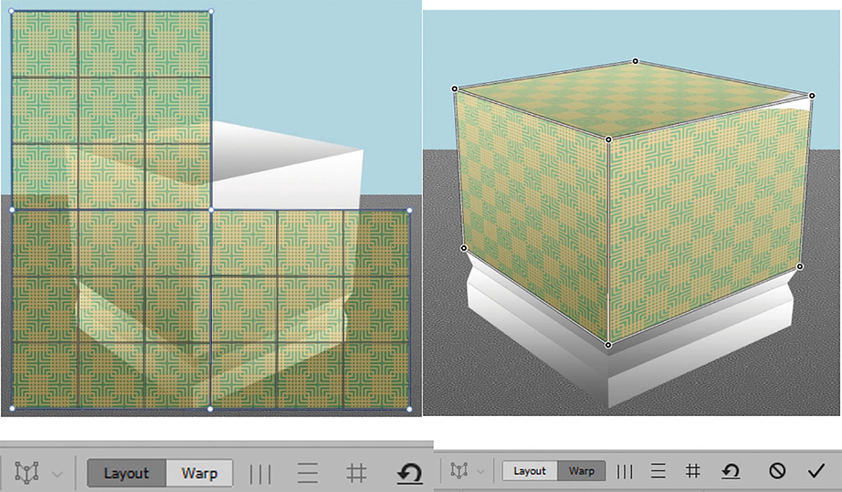
2 illustrations of a patterned L-shaped block in front of a cube and the cube with patterns on the top and both sides in the layout and warp modes.
Use Perspective Warp in Layout mode to make three planes and then manually warp using Warp mode in the Options panel

An illustration of a patterned cube. Below is an image of vector smart object copy and smart filters, above perspective warp, in the perspective warp flat covering folder.
The pattern warps around the cube seamlessly if warped correctly
Cube Perspective Coverage Distortion (Vanishing Point Filter)

An illustration of a patterned square. On the right is the selected smart object among the five choices in the paste-labeled pop-up window.
Use only a square of the graphic from Illustrator and Paste As Pixels for the Vanishing Point filter

Two images of a zoomed section of the Layers-labeled pop-up window exhibiting the highlighted layer 8 and rasterized pattern and vice versa.
Select ➤ All of the layer Rasterized Pattern and Edit ➤ Copy to clipboard and then select the blank layer and turn off the visibility for the pattern layer

An illustration of a cube with line patterns on the top and both sides. The icons for the create and edit plane tools are depicted.
Create and edit planes in the Vanishing Point filter first on the left and then create two tear-off planes on the top and then the right using those tools

An illustration of a cube with a patterned square on the upper left as a floating selection. The second illustration exhibits it and the 3 planes merging.
Paste your selection and then drag the floating selection over the three planes

An illustration of a cube that is fully covered with line patterns via the transformation tool. The tool's icon is depicted on the lower left.
Use the Transform tool to drag the edges of the selection so that it covers the box

Two capsule-shaped buttons labeled O K and cancel.
Click OK to exit the Vanishing Point filter

A set of before-and-after photographs of the removal of an unwanted pattern on the cube in layer 8.
The graphic appears on the layer and I added a layer mask to remove any extra graphic from the bottom of the box
- 1.
It is fast and straightforward to use.
- 2.
It works on smart object layers along with multiple filters, and either it or the smart object can be altered at any time without having to recopy the artwork on a new layer each time.
This is not to say that the Vanishing Point filter is not useful, as we saw in the previous two projects, but with specific warps it does have some limitations that the Perspective Warp can overcome.

An image of three highlighted folders, namely, perspective warp flat covering, perspective warp underscore wrap the cube and V P point example.
You can look in these group folders in the file if you want to explore further the options discussed here
Enhancing the Perspective Warp: Flat Surface Warp and Warps That Melt and Appear 3D-Like
So far, what we have seen was OK for flat surfaces with no additional external distortions. However, here are a few final advanced tips that you can use to make your Edit ➤ Perspective Warp appear more melted and 3D-like.

An illustration of a face in front of the patterned cube. On the lower right is a highlighted face mask layer with the face on the transparency grid.
A mask can be molded over a box if it is a smart object layer

An illustration of the face divided into a 3 by 3 grid into two planes in the layout mode. In warp mode, the illustrated face bends on the top and one side of the patterned cube.
Use the Perspective Warp to create two planes in Layout mode and bend in Warp mode in the Options panel

Two illustrations of the face before-and-after mapping and enhancing its features via the puppet warp tool. Options such as mode are depicted below.
Use Edit ➤ Puppet Warp and its Options panel when you want to stretch the face to look melted

An illustration of the melted, bent face on the transparency grid. The forward warp tool, brush tool options, and option to preview are depicted.
Use the Liquify filter for a really meted look using the Forward Warp tool and its brush tool options

An illustration of the melted face on the top and one side of the patterned cube. Below are the face mask layer and effects used such as drop shadow.
Add a layer style Drop Shadow to add a shadow to the mask
I then added a layer mask which I painted on with my Eraser tool to hide any unwanted areas around the edges of the melted mask. Refer to Figure 10-109.
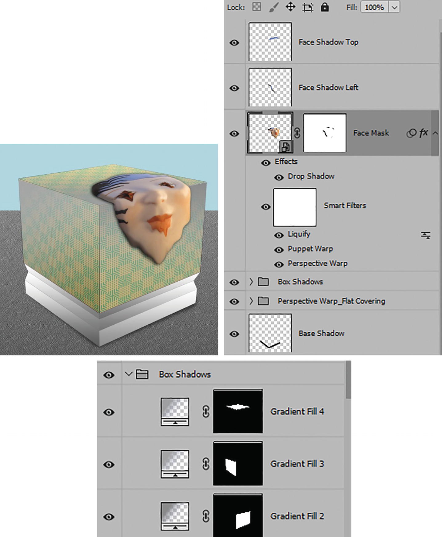
An illustration of a patterned cube with a melted face on the top and one of its sides. The box shadows folder has three observable gradient fills.
Add layers to add further shadows manually to the face and cube
This is a good example of how multiple filters on a smart object layer can be used to distort and warp an object to appear like it is melting yet still retain a 3D-like appearance using the shadows found in the original photo.
Neural Filters Workspace (Smart Portrait, Landscape Mixer)
Some of the most recent and exciting filters to be added to Photoshop are the ever-changing and improved Neural Filters. You can preview them and then decide if you want to add them to your collection if you download them from the cloud. I will talk about Smart Portrait and Landscape Mixer. However, new ones are being added every few months so make sure to check this area regularly for new distort options.

An image of a vertical stack of the icons of four options. An encircled plus sign, encircled minus sign, raised hand, and magnifying glass are depicted.
Neural Filter tools
The left-pointing arrow in the Options panel allows you to exit the Neural Filter workspace without saving changes. This is the same as clicking the Cancel button in the Neural Filter panel.
Add to selection (B) (add to current mask): This tool allows you to add to a created mask. Like most brushes, you can set the size, hardness, spacing, angle, and roundness of the brush for the mask as well as size based on Pen Pressure or Stylus wheel and Tolerance, currently set to Off.
Next is the Opacity (1-100%).
Next is the Show/Hide Mask Overlay check box and beside this you can set the mask color by clicking on the swatch and using the Color Picker dialog box.
Lastly, additional mask/selection adjustment options of Invert, Clear, Select Subject (most prominent objects in the image), Select Sky, and Reset the mask to the original state. Refer to Figure 10-112.

An options panel of the add to selection tool has a list involving opacity, show mask overlay checkbox, and masks. Other options such as size and hardness are also depicted.
Neural Filter’s Add to selection tool with its Options panel and brush options
Subtract from selection (E) (subtract from current mask): This tool is basically like the Eraser tool for the mask and has all the same settings as the Add to Selection tool, except now you are erasing the mask. Refer to Figure 10-113.

An options panel of the subtract to selection tool lists opacity, show mask overlay checkbox, and various masks, among others.
Neural Filter Subtract from selection tool with its Options panel
Hand tool (H): Allows you to move about an image when zoomed without disturbing the graphics or the painted mask. The options panel allow you several zoom presets of Scroll All Windows, 100%, Fit Screen, and Full Screen. Refer to Figure 10-114.

An options panel of the hand tool lists scroll all windows checkbox, 100%, fit screen, and fill screen.
Neural Filter Hand tool with its Options panel
Zoom tool (Z): Same as the Zoom tool in the Tools panel with the same options; it allows you to zoom in or out of an image. Other options include Resize Widows to Fit, Zoom All Windows, Scrubby Zoom, and the same three buttons found in the Hand tool of 100%, Fit Screen, and Fill Screen. Refer to Figure 10-115.

An options panel of the zoom tool lists resize windows to fit, zoom all windows, and scrubby zoom checkboxes, 100%, fit screen, and fill screen.
Neural Filter Zoom tool with its Options panel

A zoomed section of the neural filters window. The highlighted meatball menu, next to all filters and wait list tabs, displays a checked use G P U.
Neural Filters panel with GPU enabled

A set of window panels exhibits the disabled and enabled states of the beta color transfer function of the neural filters. The color space, among others, can be changed if enabled.
Neural Filters panel with Filter options and the Color Transfer filter enabled
This is how you can enable or disable all Neural filters that are available to you.
Next, I will talk about two filters in this panel that I think may be of interest for causing distorts or changes in photos. With any filters that you have never used, before you download them from the cloud, make sure to read their description first and then test one at a time.

Two images of the disabled and enabled states of the smart portrait function. Below is a cropped image exhibiting the 215.3 kilobytes for download.
Download filters but check first to see why the filter is disabled in the Neural Filters panel .
Smart Portrait (Featured)

Two portraits of a man with the same head and hand positioning styles but portraying distinct expressions on his face. An option to download the images is depicted below.
Download the Smart Portrait filter so that you can use it
If you do not have this filter active on your system already, you need to download it by clicking the Download button. Currently it is in the Portraits Section of the Neural filters while in past versions you would find it under Beta. For this example, you need to have a human face or faces present in the file for it to work.

Two capsule-shaped buttons labeled O K, which is highlighted, and cancel.
Click Cancel to exit the Neural Filters workspace so that you can locate your file
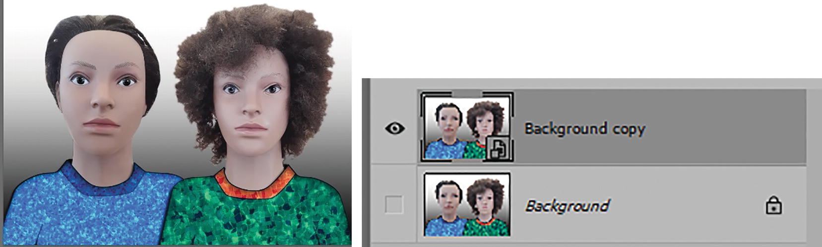
An image of two female mannequin heads dressed in patterned shirts. On the right are background copy, which is highlighted, and background layers.
Test the Neural Filter Smart Portrait on our models

A panel for the enabled smart portrait filter exhibits sliders to set the happiness and facial age, among others, of a female mannequin head.
In the Neural Filters panel, activate the filter and then select a head that you want to test the filter on
Now you can start to work with the sliders and use data that is generated in the cloud. The cloud has facial data that it has collected and, using that data, can interpret and generate new information for the face. Refer to Figure 10-122.
A selected face has been chosen but you can use the dropdown list to select the other face. Also, the check box for Auto balance combinations is enabled. Refer to Figure 10-122.
Featured: Happiness , Facial age, Hair thickness, Eye direction. The slider range for each is -50, 0, 50. Refer to Figure 10-123.
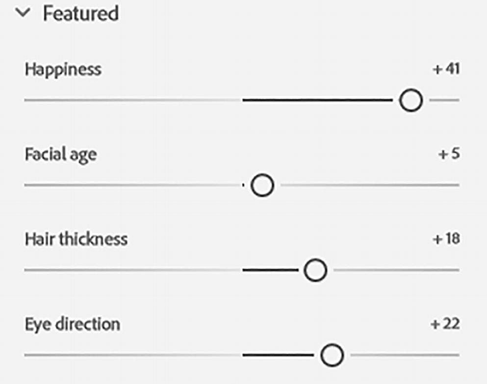
An image of the sliders for the featured options. Happiness is at plus 41, facial age is at plus 5, hair thickness is at plus 18, and eye direction is at plus 22.
Smart Portrait Featured options
Expressions: Surprise and Anger. The slider range for each is -50, 0, 50. Refer to Figure 10-124.

An image of the sliders for the options under expressions. Surprise is at negative 7 and anger is at negative 1.
Smart Portrait Expression options
Global: Head direction , Fix head alignment, Light direction. Fix head alignment is only active if you have altered Head direction. The slider range for each is -50, 0, 50. Refer to Figure 10-125.

An image of the sliders for the Global options. Head direction is at plus 6, fix head alignment is at plus 7, and light direction is at plus 9.
Smart Portrait Global options
Settings: Retain unique details runs from 0-100. The default is 90. Mask feathering runs from 0-100; the default is 10 if a mask is present. Refer to Figure 10-126.

An image of the sliders for the settings options. Retain unique details is at 96 and mask feathering is at 10.
Smart Portrait Settings options

An image of the title bar for smart portrait. The reset icon, a curved arrow atop a horizontal line, is on the right side of the title.
Reset the Smart Portrait filter if you made a mistake

An image of 2 female mannequin heads. The first wears a smile on her face after the smart feature filter was used, while the second's expression remains the same.
Alter the expression on the second face as well
The Cloud may take a moment to process as you alter the expressions.
To me, this is kind of spooky. As an idea, you could use this on an old family photo. Suddenly an ancestor could be doing things that we don’t have original photos for. Did they really make a facial expression like that? You’ll never really know. I think it will be interesting to see how this filter will improve over time. Things that I hope that will be added in the future are the ability to open and close eyes, eye color alterations, nose and ear adjustments, more teeth options, and being able to modify animal faces like cats and dogs. Perhaps the upcoming wait listed filter called Portrait Generator will do much of that?

A panel for the neural filters exhibits options to show the original and to show all layers and show selected layers in the output.
View options for Neural filters

A drop-down menu of the choices for the output of neural filters, namely, current layer, new layer, new layer masked, smart filter, and new document.
Output options for your Neural Filters
In this case, because we are working with a smart object layer, choose smart filter from the list in case you want to edit the file another day.

A screenshot of a panel with a smart filter as the selected output option. On the right are capsule-shaped OK and cancel buttons.
Choose the Output option of Smart filter and click OK to exit

A screenshot of two female mannequin heads below an image of highlighted background copy layer, smart filters, and neural filters.
The filter is applied to your smart object layer
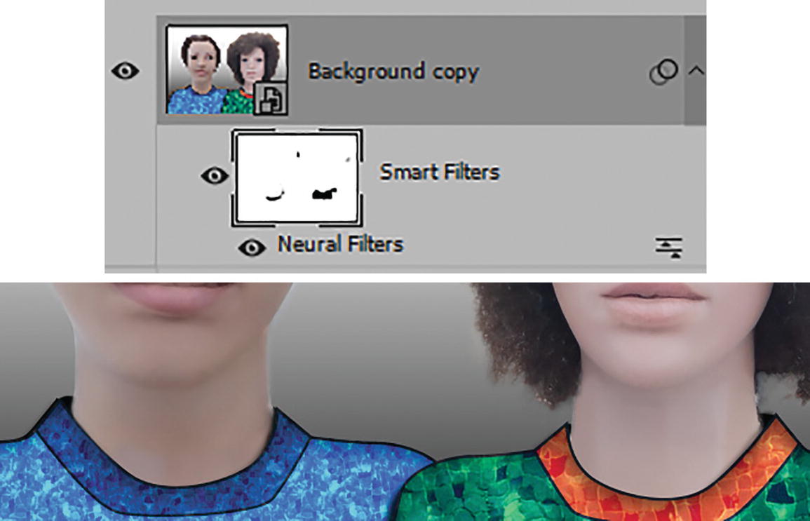
A screenshot of the respective neck area of the two female mannequin heads. Above is an image of highlighted background copy layer with filled smart filters and neural filters.
Use an Eraser tool to blend and alter areas on your Smart Filters mask around the neck area
This filter also comes with Blend Mode options.
File ➤ Save your document as a .psd file. You can view my file womens_heads_final_smart_portrait.psd.
Landscape Mixer (Beta)

Four beta filters with a highlight on the disabled landscape mixer. Below are photographs of the same valley before and after applying the filter and the download option.
Download the Neural Filter Landscape Mixer
Once you have downloaded the filter, click Cancel to exit and locate the landscape you want to work with. File ➤ Open IMG_3030_landscape_mixer_start.psd and then make an Image ➤ Duplicate. While it is to me a beautiful image, it was a rather rainy day and I think Landscape Mixer can improve the image.

A photograph of a river in the woods in between an image of a highlighted background copy layer and enabled landscape mixer filter.
Using a smart object layer, activate the Landscape Mixer filter in the Neural Filter workspace

A panel for the landscape mixer panel exhibits an opened presets tab with photographs of various landscapes. The option to select an image is present below.
Use a preset or custom image to alter your landscape

Two sets of 2 photographs of landscapes pre- and post-use of landscape mixer. A lake at the foot of a snow-capped mountain and a mountaintop in the morning are turned into a river in the woods in different seasons.
These are the presets I used on the same photo

Two sliders for the landscape mixer options. Strength, day, night, sunset, spring, summer, autumn, and winter can be set from 0 to 100.
Landscape Mixer Filter options
Wow! You would never know it was the same photo. In many ways, this reminds me of experiments I did with the Color Lookup adjustment layer and LUTs. However, this is more complex in the fact that part of the landscape and not just colors are being blended together.
You can then use the sliders for Strength, Day, Night, Sunset, Spring, Summer, Autumn, and winter. The range for these sliders is 0-100. Refer to Figure 10-138.

A photograph of a river in the dark-lit woods. The rushing water is colored in a combination of blue and orange.
Adding more night to the sunset scene is quite magical

A screenshot of two checkboxes labeled preserve subject and harmonize subject.
Additional Landscape Mixer filter options
The checkboxes Preserve Subject and Harmonize Subject are currently disabled. Refer to Figure 10-140.

A screenshot of the title bar for the landscape mixer. The reset icon, a curved arrow atop a horizontal line, is on the right side of the title.
Reset the Landscape mixer filter

A screenshot of a panel with a smart filter as the selected output option. On the right are capsule-shaped buttons labeled OK and cancel.
Output the setting as a smart filter and click OK to commit

A screenshot exhibits the presence of a smart filter with neural filters below it and the background copy layer above.
The smart filter now appears in the Layers panel
Due to the fact that this filter is in Beta, some settings and sliders may have altered depending on what version of the filter you are using, so your results may look slightly different than mine and you may have to adjust additional sliders. Filters without the beta label are more stable, so once this filter reaches that status, the colors and settings should be more accurate.
If you are interested in how color lookup relates to alterations in the look of an image’s color, make sure to check out this link: https://helpx.adobe.com/photoshop/how-to/edit-photo-color-lookup-adjustment.html .
Other Neural Filter Options
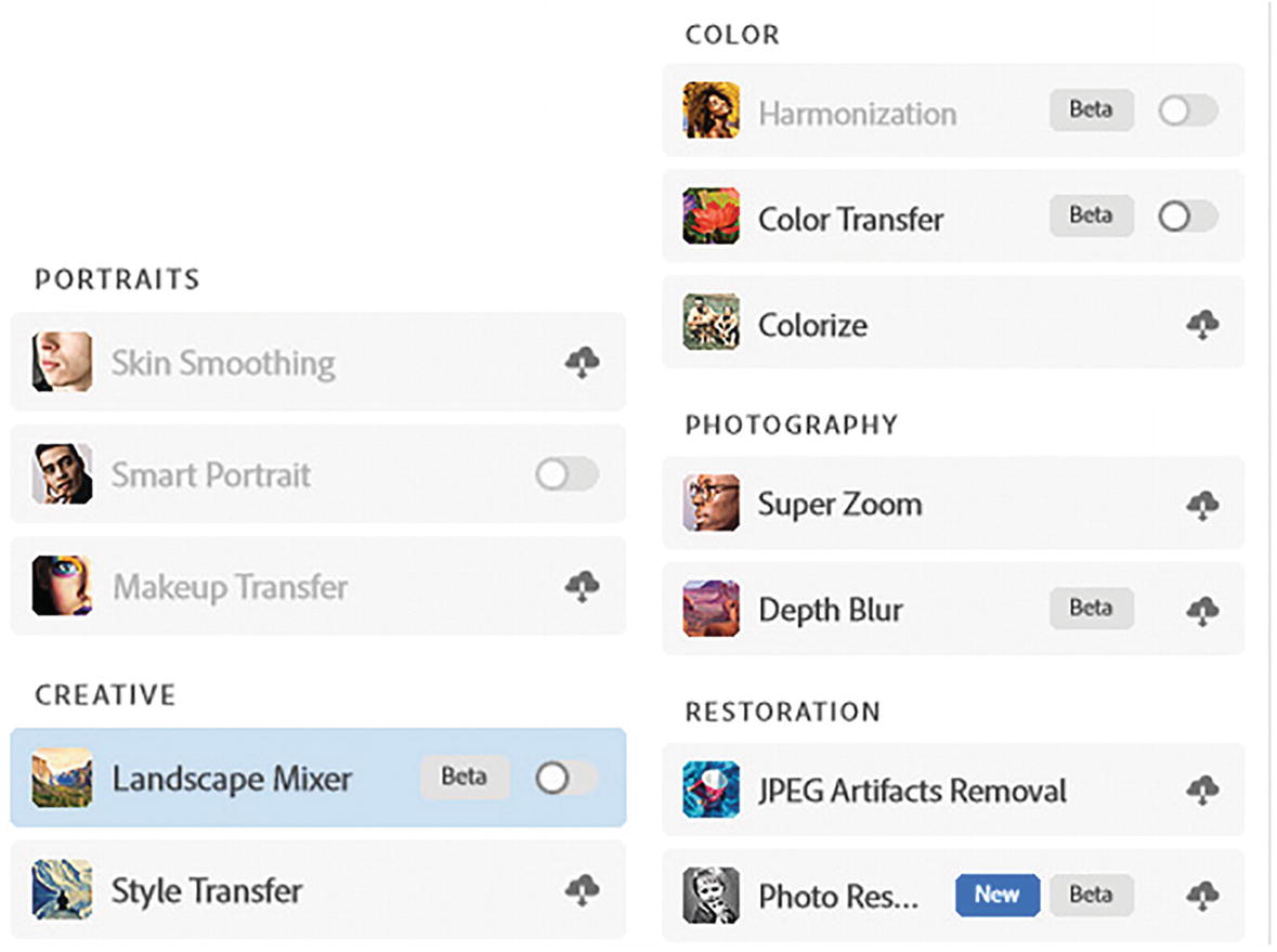
A screenshot of the featured and beta sections of neural filters. Colorize and style transfer and depth blur and color transfer are some of the filters present.
On your own, take time to look at other Neural Filters in the various sections

A menu displays 4 filters in the wait list tab and highlights the portrait generator with a set of 8 photographs on the right. 2 photos of a half-collapsed wall before and after shadow and lighting.
The wait list mentions neural filters that will be added at some point to the collection
For more information on filters and the new Neural filters, refer to these links :
https://helpx.adobe.com/photoshop/using/filter-effects-reference.html
https://helpx.adobe.com/photoshop/using/neural-filters-list-and-faq.html
https://helpx.adobe.com/photoshop/using/neural-filters.html
https://helpx.adobe.com/photoshop/using/neural-filters-feedback.html
Acquiring Additional Filters via Creative Cloud
Besides Neural Filters, you can acquire additional Photoshop filters online. Just make sure that they match with your current version of Photoshop and update them if they no longer work in newer versions.
Third-Party Plugins

A menu exhibits the plugins panel, highlighted browse plugins, and manage plugins options under the plugins tab on Photoshop.
Use your Photoshop menu to browse for plugins

A Creative Cloud Desktop application exhibits opened stock and marketplace and plugin tabs. All plugins are highlighted on the left panel and are expanded on the main panel, exhibiting watermark 3 and pixel squid, among others.
Creative Cloud desktop can help you locate other filters

A section of the Creative Cloud Desktop application exhibits an opened stock and marketplace tab and plugins panel. From Photoshop and filters search entries, Geographic Imager, Raya Pro 6, and Adobe Exchange are present.
Stock and Marketplace under the Plugins tab is a good place to find more filters

A screenshot of a Cloth Texture Generator entry from Adobe Research Imagination Lab. The Photoshop logo and learn more text are present on each end below.
Click on the Plugin name when you want to find out more about a filter or Plugin
Summary
In this chapter, you looked at more advanced filters and workspaces. You saw how to combine filters from this chapter and past chapters. You also saw that Photoshop has some new Neural Filters that are content-aware and can assist you in altering your images in unique and unexpected ways.
Saving for Print

A pop-up window labeled layers exhibits a stack of layers with the flatten image option highlighted in the menu below merge down and merge visible. Above is the file name and below is the background layer.
Use the Layers panel menu to flatten a copy of your file before you convert it to CMYK Color mode

A screenshot of a checked 8 bits per channel option from the C M Y K color entry via the mode function under Photoshop's Image tab. A warning message pops up regarding the conversion.
Before converting to CMYK mode, you may see a warning message. Click OK to convert to that profile
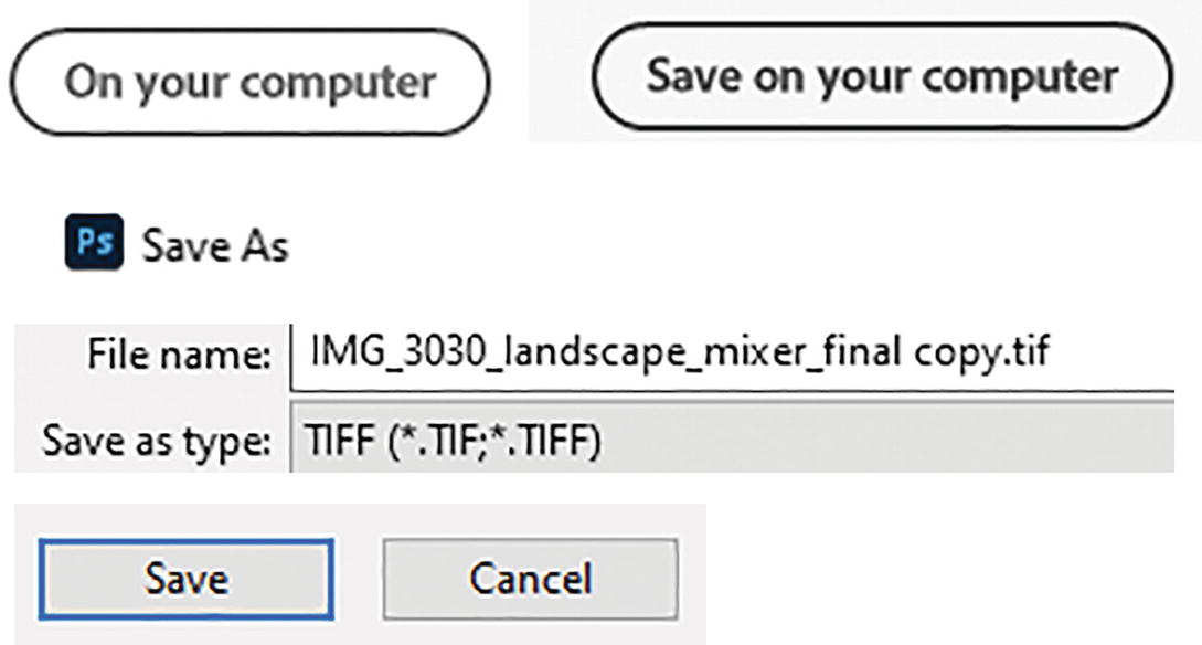
A zoomed section of the application exhibits a filled input field for the file name and T I F F as the choice for the save as type option.
Save your file as a .tiff before you print it on your home printer

A pop-up window labeled T I F F options. It features image compression, pixel order, byte order, and layer compression sections along with checkboxes.
Tiff Options dialog box save settings
I hope that you enjoyed working with the Photoshop projects in this volume of the book and that you saw how you can use Illustrator files as well to enhance your work in Photoshop.
Further Suggested Reading
Wow, after reading this book, you can now successfully create your own warps and distorts in Photoshop. So, what is the next step you should take?
If you are interested in focusing on Adobe Illustrator, get a copy of Volume 2, where I will be looking at how similar warps and distorts can be applied using Illustrator tools and effects. I’ll also offer information about other Adobe applications that you can use to enhance your next project further.