Chapter 6
Characterization of a PV Module
6.1 Introduction
This laboratory will explore the behavior of a photovoltaic module under a variety of environmental conditions, as well as provide a strong foundation for its use in PV systems.
We introduce the concept of a current-voltage (I-V) characteristic, which specifies the current and voltage produced by a PV module as a function of the load resistance connected to it. We will discover how the I-V characteristic varies as a function of the sun’s irradiance striking it and also as a function of the temperature of the cells which comprise the PV module. We will discover that at a given irradiance and temperature, there is a maximum power that can be delivered by a PV module to a unique load resistance.
During the course of this laboratory we will come to understand how the individual cell size and the number of cells in a module determine the module currents, voltages, and powers.
In Chapter 7, as a follow-up to this chapter, we will use PSpice® to develop fairly sophisticated models for a PV cell and for a PV module and we will compare the results of simulating the I-V characteristic of the PSpice model against measured data.
6.2 Student Learning Objectives
At the end of this lab the student will be able to
- Distinguish the key characteristics of a photovoltaic module by measuring voltages and currents under a variety of environmental conditions
- Identify the instruments needed to make the necessary measurements
- Compare these measurements with those contained in the manufacturer’s data sheet
6.3 Setup
This laboratory will involve a number of fairly sophisticated instruments and measurements. The focus of these activities will be a commercially available, 36-cell, 100 W PV module. The following is an introduction to the PV module and instruments that we will use during the lab.
6.3.1 The TiltAll Tripod
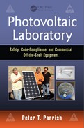
We will mount the PV module that we wish to characterize on a rugged tripod, the TiltAll TE Professional (see Figure 6.1). This tripod comes with three sturdy, adjustable legs; adjustable vertical extension with lock; and three sets of adjustable axes with locks: azimuth, elevation, and cross-elevation. The cross-elevation axis will not be used in this class, although it is useful in photography. This tripod can easily support a 16 kg (35 lb.) load.

Figure 6.2 depicts the four adjustment/locking knobs: vertical extension (lower left), azimuth (lower right), elevation (upper right), and cross-elevation (upper left).
Four adjustment/locking knobs: vertical extension (lower left), azimuth (lower right), elevation (upper right), and cross-elevation (upper left).
6.3.2 Choice of PV Module—The Renogy RNG-100D
For this laboratory, as well as for others, we will need to pick a PV module to work with. For over 30 years, one of the most popular PV modules has been referred to as a “12V nominal PV module” because, at typical operating temperatures, the value of Vmp is just above 14.4 V set point for acceptance charging of nominal 12V lead acid batteries. This module is composed of 36 cells and has historically been used with 12V battery systems. Depending on the cell technology (monocrystalline vs. polycrystalline), size (5 in. vs. 6 in. square), and surface treatment of the glass and silicon cell surface, the maximum power output can range from 100 to 140 W. Another popular PV module is the 60-cell module designed for grid-tied applications. Several manufacturers offer 60-cell modules with 6 in. square cells that have a maximum power rating in the neighborhood of 245 W.
In the 36-cell category, we choose the Renogy RNG-100D PV module. The data sheet for this module gives the following information:
- Solar cell: monocrystalline, 125 mm (5 in.) by 125 mm (5 in.)
- Length, width, and thickness of frame: 1195 mm (47.0 in.), 541 mm (21.3 in.), 35 mm (1.4 in.)
- Weight: 7.5 kg (16.5 lb.)
- Open circuit current (standard test conditions [STC]): Voc = 22.5 V
- Temperature coefficient of Voc: Tcoef,Voc = (ΔVoc/Voc)/(ΔT) = –0.30%/°C
- Short circuit current (STC): Isc = 5.75 A
- Temperature coefficient of Isc: Tcoef,Isc = (ΔIsc/Isc)/(ΔT) = +0.04%/°C
- Maximum power output (STC): Pmp = 100 W
- Temperature coefficient of Pmp: Tcoef,Pmp = (ΔPmp/Pmp)/(ΔT) = –0.50%/°C
- Maximum power point: Vmp = 18.9 V and Imp = 5.29 A
- Nominal operating cell temperature (NOCT): 47°C ± 2°C
- Connectors: MC4
Other 36-cell, nominal 12 V modules on the market today include the Kyocera KD-140SX-UFBS (~6 in. square, polycrystalline cells), the SunWize SW-110P (~5 in. square, polycrystalline cells), and the Mitsubishi PV-MF130 (6.14 in. square polycrystalline cells). If another module is used for this laboratory sequence, there should not be a great deal of difference in the way in which the laboratory is run or the outcomes.
In Figure 6.3, we show the RNG-100D mounted on the TiltAll tripod. Note that the top edge of the frame of the PV module at the left is equipped with Velcro so that an irradiance meter can be attached to the PV module.

6.4 Components and Instruments
6.4.1 The Gnomon
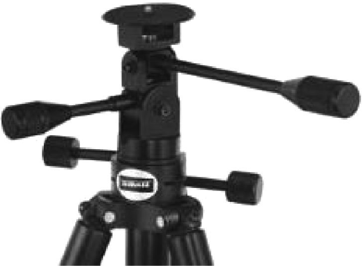
Figure 6.4 depicts the gnomon, a physical object that is used to cast the sun’s shadow. Our gnomon is nothing more than a wooden dowel sharpened to a point at one end and cut perpendicular to the axis of the dowel at the other end. In this case, we have a wooden dowel, 1.0 cm (7/16 in.) diameter, 15.2 cm (6 in.) long.

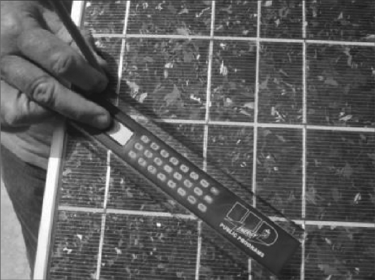
The gnomon will be placed on the surface of the PV module and the resulting shadow will be measured. The ratio of the gnomon length to its shadow will determine the angle of the PV module relative to the sun. Figure 6.5 depicts a ruler used to measure the gnomon length and the gnomon’s shadow.
6.4.2 Digital Multimeter (DMM)
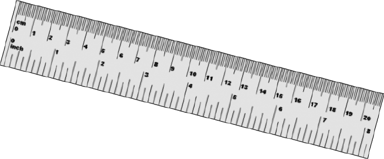
We will need to measure voltage, current, and temperature repeatedly during this laboratory. For the purposes of measuring voltage, we will use a digital multimeter (Extech Model 310; see Figure 6.6). This is a multipurpose instrument that can measure direct current (DC) and alternating current (AC) voltage, DC and AC current, resistance, and temperature (using a bead wire thermocouple). It does not employ RMS algorithms to measure AC voltages or currents.
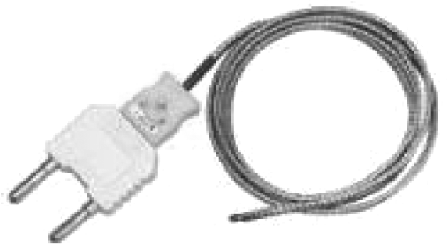
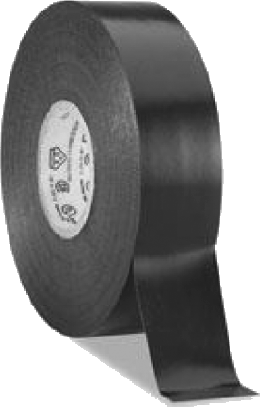
6.4.3 Bead Wire Thermocouple and Black Electrician’s Tape
Figure 6.7 shows the bead wire thermocouple used in conjunction with the DMM. When using it, make sure to observe the proper polarity. We will use it to measure the temperature of the back of the PV module. Black electrician’s tape (see Figure 6.8) will be used to affix the thermocouple to the back of the PV module. It will also be used as a target for the infrared thermometer (see Section 6.4.5).
6.4.4 Clamp-On Ammeter
It is inconvenient, not to mention potentially hazardous, to have to disconnect a conductor from its termination in order to insert an ammeter into the circuit for current measurements. A better solution is to use a clamp-on ammeter. This instrument clamps over a wire in situ and can measure the DC or AC current flowing in the wire without breaking the circuit continuity. For this laboratory, we have chosen the Extech 380942 for this purpose (see Figure 6.9).

6.4.5 Digital Infrared Thermometer
The digital infrared thermometer is a noncontacting instrument that measures the infrared power emitted by an object and converts that power into a temperature. We will use the Extech Model 42500 to measure the back of the PV module and compare this measurement with that of the IR thermometer (see Figure 6.10).
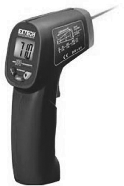
Care must be taken when using this instrument. It works by measuring the infrared radiation emitted by an object. The amount of infrared radiation is proportional to the emissivity of the object, which should be as close to 100% as possible. Applying one or more pieces of black electrician’s tape to the object under investigation serves as a high emissivity target.
6.4.6 Irradiance Meter
The Daystar™ irradiance meter (see Figure 6.11) will be used to measure the irradiance. We will use this instrument two ways. The first is to point it at the sun to get the maximum irradiance. The second is to place this instrument perpendicular to the surface of the PV module (using the Velcro pads supplied) and thereby measure the incident solar irradiance perpendicular to the PV module. The Daystar irradiance meter uses a small PV cell as the basis for its measurement.

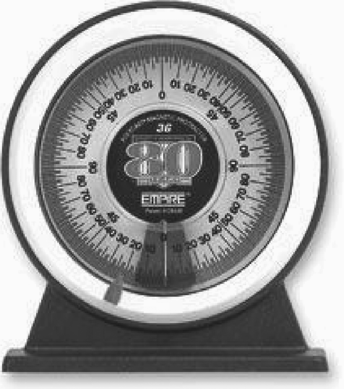
6.4.7 Tilt Meter
A tilt meter (a/k/a protractor) measures the inclination or pitch of a surface with respect to level. We will use a tilt meter on the surface of the PV module and measure the elevation or tilt angle of the PV module with respect to level. See Figure 6.12.
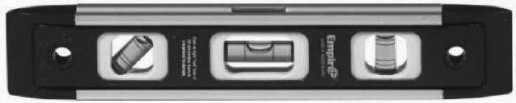
6.4.8 Torpedo Level
In order to ensure that a surface is level or plumb (90° with respect to level) we will use a small spirit level, referred to in the trade as a “torpedo level.” We will use a model 9 in. long with a magnetic bar, and three spirit bubbles—in this case, “level,” “45°,” and “plumb.” See Figure 6.13.
6.4.9 Thermometer
In order to measure the ambient temperature, we will use a laboratory-grade thermometer and calibrate in degrees Celsius. See Figure 6.14.

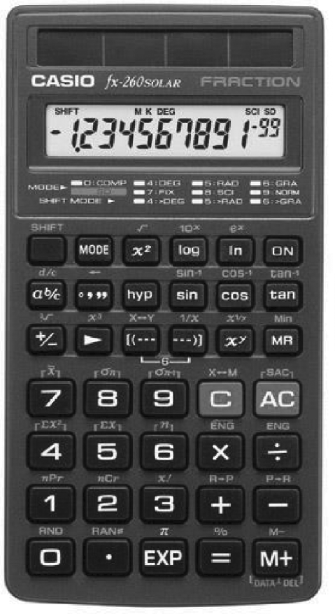
6.4.10 Calculator
We will need to make a series of field calculations during this laboratory. A good, solar-powered calculator with trig and inverse trig functions is the Casio fx-260 solar calculator (see Figure 6.15).
6.5 Student Exercises
6.5.1 The Measurements
We will use the Renogy RNG-100D for this part of the laboratory. See Table 6.1 for the key performance parameters and Table 6.2 for the temperature sensitivity of these parameters.
Renogy RNG-100D Monocrystalline PV Module Electrical Characteristics
|
Open circuit voltage Voc |
Short circuit current Isc |
Maximum power Pmax |
Maximum power voltage Vmp |
Maximum power current Imp |
|
22.5 V |
5.75 V |
100 W |
18.9 V |
5.29 A |
Temperature Sensitivity of the Electrical Characteristics
|
Renogy RNG-100D monocrystalline PV module temperature coefficients |
||
|
Open circuit voltage |
Short circuit current |
Maximum power |
|
–0.30%/° C |
+0.04%/° C |
–0.44%/° C |
First, we will make a number of measurements of the environment: maximum irradiance, ambient temperature, and module temperature. These measurements are important because the electrical characteristics of a PV module depend on irradiance and temperature.
Second, we will make a series of current and voltage measurements of the PV module. We will vary the irradiance perpendicular to the module, by varying the angle of the module with respect to the sun. We may be able to make measurements at two different ambient temperatures; however, this will depend on the weather. The measurements for this laboratory are as follows:
- Measurement 1: maximum irradiance IRRmax
- Measurement 2: the gnomon and the “cosθ” law
- Measurement 3: IRRmax, when PV module is pointed directly at the sun
- Measurement 4: irradiance when PV module is not pointed directly at the sun
- Measurement 5: module temperature—two ways to measure
- Measurement 6: ambient temperature
- Measurement 7: Voc, the open circuit voltage
- Measurement 8: Isc, the short circuit current
- Measurement 9: MPP, the maximum power point
- Measurement 10: the I-V characteristic
6.5.1.1 Measurement 1: Maximum Irradiance
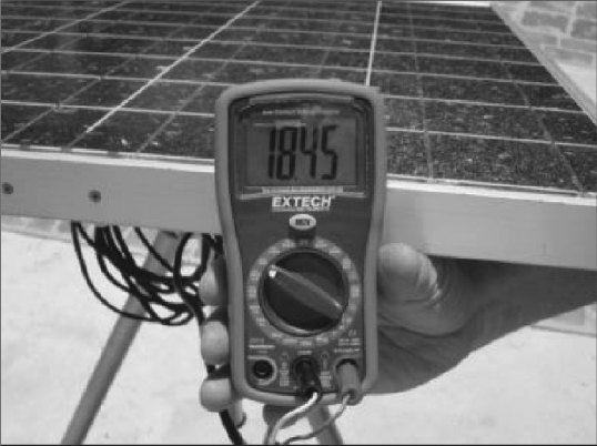
Holding the Daystar irradiance meter in your hand, find IRRmax, the maximum irradiance, by pointing the Daystar meter directly at the sun (see Figure 6.16). Move the Daystar meter slightly side to side and up and down to obtain a maximum reading. Record this number.
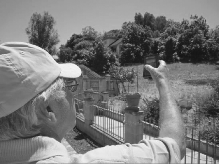
□ IRRmax = ______ W/m2
6.5.1.2 Measurement 2: The Gnomon and Measuring the Angle of Incidence
By temporarily fixing a gnomon perpendicular to the surface of the PV module, we can measure the shadow cast by the gnomon to determine the angle of the perpendicular to the PV module relative to the angle of the sun. Specifically, if the PV module is adjusted so that there is no shadow, then we know that the perpendicular to the PV module is pointed directly at the sun.
In Figure 6.17, we have constructed a right triangle whose two legs are the gnomon length (L) and the gnomon shadow (S). The angle Θ is the angle between the perpendicular to the PV module and the sun.
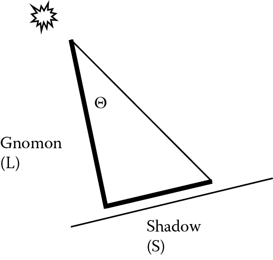
From basic trigonometry,
tanθ=(S/L)
or
θ=tan−1(S/L)
The “inverse tangent” function is available on the Casio calculator by using the “Shift” button.
Position the gnomon perpendicular to the surface of the PV module. Lock the azimuth bearing. Adjust the elevation bearing of the tripod to obtain a shadow 3–5 cm long, and lock the elevation bearing. The exact length of the shadow is not important. Measure and record the length, S, of the shadow. See Figure 6.18.
□ S = ______ cm
Using the gnomon length of 15.2 cm and the length of the gnomon shadow, calculate the angle Θ:
□ Θ = ______ °.
6.5.1.3 Measurement 3: Irradiance When PV Module Is Pointing Directly at the Sun
Again, locate the tripod on reasonably level terrain. Use the adjustable legs to level the tripod base using the torpedo level and the elevation shaft of the tripod. Attach the thermocouple to the back of the PV module just above its center, using three strips of black electrician’s tape to fix the thermocouple wire bead in place.
Connect the MC-4 connectors of the PV module to the DMM using the cables that convert from MC-4 to banana plug. (When the back-side temperature of the PV module is measured using the thermocouple, the PV module leads will need to be swapped out in favor of the thermocouple plug.)
Place the gnomon perpendicular to the surface of the PV module. Adjust the azimuth and elevation of the PV module so that the gnomon does not cast a shadow. Lock the azimuth and elevation bearings. No shadow means that the PV module has an angle of incidence equal to zero (pointed directly at the sun) and should be receiving the same maximum irradiance IRRmax as in measurement 1. Remove the gnomon. Measure the irradiance with the irradiance meter as shown in Figure 6.19 (or attach it to the top side of the PV module using the Velcro provided):

□ Irradiance = ______ W/m2
Compare this reading to measurement 1. Can you think of a reason why they might not agree? Has there been a change in the sky conditions (clear, hazy, overcast)? ______________________________________________________________
6.5.1.4 Measurement 4: Irradiance When the PV Module Is Not Pointed at the Sun
This measurement is designed to confirm the cosΘ law, which relates the maximum irradiance to the irradiance normal to the PV module when not pointed directly at the sun.
Place the Daystar irradiance meter perpendicular to the PV module (or use the Velcro attached to the side of the module). Repeat measurement 2: Place the gnomon on the PV module again and measure the length of the shadow it casts. Record the length of the shadow:
□ S = ______ cm
Using the gnomon length of 15.2 cm and the length of the gnomon shadow, calculate the angle Θ:
□ Θ = ______ °.
Now measure the irradiance perpendicular to the PV module. Record the irradiance:
□ IRR (Θ) = ______ W/m2
Calculate the ratio of the irradiance IRR to the maximum irradiance IRRmax:
□ Ratio = cos(Θ) = [IRR(Θ)/IRRmax] = ______
Calculate Θ:
□ Θ = ______
Compare it to the preceding ratio.
Another way of stating what we may have just confirmed is to say that the new irradiance value and the value obtained when the sun’s rays were perpendicular on the PV module (gnomon yielded no shadow) are related by the expression
IRR(Θ)=IRRmax×cosΘ
6.5.1.5 Measurement 5: Module Temperature—Two Ways to Measure
Adjust the azimuth bearing so that the PV module is pointed toward the sun (exact angle is not important). Wait 5 minutes. Point the IR thermometer at the black electrician’s tape at the back side of the PV module, as shown in Figure 6.20. Measure and record this reading in degrees Celsius. This will not be exactly the cell temperature, because of the intervening Tedlar backing, but it will be close to it:

□ T (module, IR) = ______ °C
Attach the thermocouple leads to the DMM as shown in Figure 6.21 and record the temperature:
Measuring the back-side temperature of a PV module with the thermocouple and the model 310 DMM.
□ T (module, thermocouple) = ______ °C.
Calculate the difference in temperature using these two techniques and express the result as a percentage:
ΔT(percent)=(Tthermocouple−T1R)T1R×100
□ ΔT/T = ____________________ %
□ Can you think of a reason why the two measurements differ?
□ What is the accuracy of the DMM in temperature mode?
□ What is the accuracy of the infrared thermometer?
□ Do the two measurements agree to within the relative accuracies of the two instruments?
6.5.1.6 Measurement 6: Ambient Temperature
Since a significant fraction (~70%) of the sun’s power is absorbed by a PV module and turned into heat, the temperature of a PV module can be considerably higher than the ambient temperature. This difference can be as much as 25°C on a sunny day without much wind.
The antireflection coatings on the glass and on the surface of a Si cell and the surface treatment of the Si cell (e.g., microgrooving) maximize the amount of irradiance that actually is absorbed by the PC cells. Also, the color of the module frame affects the amount of irradiance absorbed by the frame proper. Thus, all of these are contributing factors to the amount of solar irradiance absorbed by the module and converted to heat. The composition of the back-side encapsulation also is a factor in the resulting module temperature, as modules radiate some of the heat away. Finally, wind can carry away some of this heat by convection so long as the ambient temperature is less than the module temperature.
Measure the ambient temperature using the laboratory-grade thermometer provided. Take care to keep the thermometer in the shade so that it is not heated by direct sunlight:
□ T (ambient) = ______ °C
What is the difference between the module temperature as measured by the IR thermometer here and the ambient temperature?
□ T (module, IR) – T (ambient) = ______ °C
The module temperature is an important variable; we will find out later that the power output of a PV module goes down with increasing module temperature.
6.5.1.7 Measurement 7: Standard Operating Conditions (SOCs) and Nominal Operating Cell Temperature
In addition to standard operating conditions, manufacturers also specify an expected cell (or module) operating temperature, referred to as NOCT. NOCT is the expected temperature of an open-circuited module subjected to an irradiance of 800 W/m2, an ambient temperature of 20°C (68°F), and a wind speed of 1 m/s. 800 W/m2 is closer to the typical irradiance experienced by a module than 1000 W/m2 is.
We would expect NOCT to vary from module to module because of differences in module construction and the consequent heat transfer characteristics.
For the Renogy RNG-100D, NOCT = 47°C ± 2°C. In other words, under the preceding test conditions, the temperature of the RNG-100D exceeds that of ambient by ΔT = 27°C.
□ What is the module temperature, Tmodule, determined from the infrared thermometer? ______ °C
□ What is the ambient temperature, Tambient? ______ °C
□ What is the difference between Tmodule and Tambient? ______ °C
□ How does this measured temperature difference compare with 27°C? _______
□ What reasons can you think of that might cause a difference between these two temperature differences?
6.5.1.7.1 Electrical Measurements of the PV Module under Different Load Conditions
In the next three measurement sequences, we will measure the electrical characteristics of a PV module under different load conditions. By load conditions, we mean the value of the external load resistance connected to the PV module.
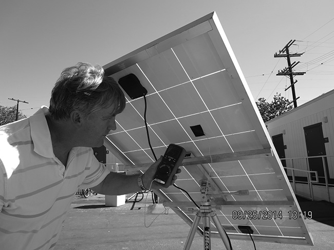
The first measurement is Voc, called the open circuit voltage. See Figure 6.22. This measurement is made without drawing any current. This is achieved by using the DMM, set to measure DC voltage. When measuring voltage the DMM presents a very high resistance to the PV module. Hence, the DMM draws a negligible amount of current and this is a good way to measure Voc.
The second measurement is Isc, called the short circuit current. See Figure 6.23. This measurement is made without allowing any voltage to be present at the terminals of the PV module. This is achieved by using the DMM set to measure DC current. Alternatively, we can also short the leads of the PV module together, measuring the resulting current with a clamp-on-ammeter.

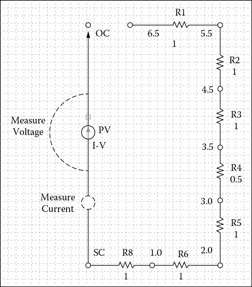
The third measurement is made with a finite load resistance, which results in both current and voltage being present at the same time. See Figure 6.24 for the experimental arrangement and Figure 6.25 for the equivalent circuit.

At the factory, all PV modules are characterized using STC by illuminating the PV module with 1000 W/m2, at an angle of incidence equal to zero, a spectrum equivalent to a 1.5 air mass, and a module temperature of 25°C (77°F). This is accomplished by using specially calibrated high-intensity flash lamps; the measurements are made in a fraction of a second, which does not allow the temperature of the PV module to vary from the ambient temperature, which is kept at 25°C.
6.5.1.8 Measurement 8: Voc , the Open Circuit Voltage
Refer to the PV module data sheet and set the DC voltage of the DMM to be just above the Voc (at STC) from the data sheet. Plug the positive and negative leads into the DMM V/Ω /mA and COM jacks, respectively. Record this reading:
□ Voc = ______ V
Measure the back plane temperature of the PV module using the thermocouple and the DMM. Record this value:
□ T (module, thermocouple) = ______ °C
Is the measured value of Voc equal to the Voc specification on the data sheet? It rarely is and the reason for this difference is that we are not making our measurements at STC. What we can do is to take the STC value and correct for the differences in temperature and irradiance. It turns out that Voc depends only slightly on irradiance and we will ignore it in this laboratory.
The electrical characteristics of the RNG-100D module are listed in Table 6.1, and the temperature sensitivities of these characteristics are listed in Table 6.2. We have the following value for Voc at STC and its temperature coefficient:
- Voc = 22.5 V
- Tcoef = ΔVoc/Voc = –0.30%/°C
Based on the measured back plane temperature, we now adjust the STC value of Voc, using the following equation:
Voc(T)=Voc(25°C)×[1+Tcoef100×(T−25°C)]
Record this quantity:
□ Voc (T) = ______ V
Remember that Tcoeff is a negative quantity, so, as the temperature exceeds 25°C, Voc goes down.
□ How does this published value for Voc (suitably temperature corrected) compare with your measurements?
6.5.1.9 Measurement 9: Isc, the Short Circuit Current
To first order, Isc is essentially proportional to the irradiance incident on the PV module. For example, if the irradiance normal to the PV module drops by 50%, Isc should drop by 50% (all other parameters remaining constant). Isc is also a weak function of module temperature. We will look at this weak dependence on temperature later.
We have the following value for Isc at STC for the RNG-100D:
- Isc = 5.75 A
Since STC assumes an irradiance of 1000 W/m2, we need to correct the STC value for the actual irradiance:
Isc,IRR=Isc(STC)×(IRR/1000)
where IRR is the actual irradiance normal to the PV module.
Measure and record IRR:
□ IRR = ______ W/m2
Using the STC value Isc, use the above equation to correct the value of Isc from the data sheet (STC).
□ Record the irradiance-corrected value for Isc: ______ A.
Are the two measurements consistent with the irradiance corrected value? ____________ (yes, no)
Based on Isc under STC (from the data sheet) and the value of IRR, and the value of IRR, set the scale of the clamp-on ammeter and zero-out the reading. Then open the jaws of the meter and place them around the PV lead. Record Isc:
□ Isc,IRR,clamp-on = ______ A
Disconnect the leads from each other and plug them into the DMM using the COM and 10 A jacks. Record Isc:
□ Isc,IRR,DMM = ______ A
Compare these two measurements:
□ Isc,IRR,clamp-on – Isc,IRR,DMM = ______ A
Are they consistent within the respective accuracies of the two instruments? ______________________________________________________________________
□ What reasons can you think of for these two values being different? ______________________________________________________________________
It turns out that the short circuit current is a function of the ambient temperature; in fact, it is positive. However, the sensitivity, +0.04%/°C, is an order of magnitude smaller than that for Voc , and we will not correct Isc for temperature.
6.5.1.10 Measurement 10: The Full I-V Characteristic
Characterizing a PV module by its I-V characteristic requires measuring the current and voltage at a number of load resistances. If we make enough measurements, we can plot the data as a “scatter plot” on a piece of graph paper and attempt to draw a “smooth curve” through the data points.
The I-V characteristic depends on a number of environmental parameters, including ambient temperature, wind speed, irradiance, and solar spectrum. For the purposes of this laboratory, we will ignore wind speed and solar spectrum. As before, we will measure the back-side temperature of the PV module with the thermocouple and the irradiance with the Daystar meter.
In order to have the PV module deliver power to an external load, we must have nonzero values for both voltage and current, at the same time. In our two previous measurements, we had one without the other. In other words, under conditions of either open circuit or short circuit the module delivers no power.
In order to deliver power to an external load, we have created a series of resistor strings (see Figure 6.25), allowing us to vary the load resistance: 0 Ω (short circuit), 1Ω , 2Ω , 3Ω , 3.5Ω , 4.5Ω , 5.5Ω , 6.5Ω , and ∞Ω (open circuit). First, we connect the output of the PV module to just one 1 Ω resistor and measure the resulting current (using the clamp-on ammeter) and voltage (using the DMM). Then we move the alligator clip over one space to create a load of 2 Ω and repeat the measurement. Continue these measurements until the current and voltage have been measured for all seven values of load resistance.
The product of the measured current and voltage will be the DC power delivered by the PV module to any given load.
In the following table, enter your current and voltage measurements, as well as the product of the two, the power:
|
I-V characteristicS for IRR = _______ W/m2 T(module) = _______ |
|||
|
Resistance (ohms) |
Current (amps) |
Voltage (volts) |
Power (watts) |
|
0 Ω (short circuit) |
|||
|
1 Ω |
|||
|
2 Ω |
|||
|
3 Ω |
|||
|
3.5 Ω |
|||
|
4.5 Ω |
|||
|
5.5 Ω |
|||
|
6.5 Ω |
|||
|
Open circuit |
|||
Plot these measurements on the following graph and draw a smooth curve through the data points.

6.5.1.11 Measurement 11: Maximum Power Point, Pmax
Looking at the I-V characteristic data, what is the maximum power Pmax for this module?
□ Pmax = ______ W
What are the corresponding values of the current, Imax, and voltage, Vmax, at the maximum power point?
□ Vmax = ______ V
□ Imax = ______ A
What is the load resistance, Rmax, for which Pmax is obtained?
□ Rmax = ______ Ω
Again, as before, let us compare this measured value of Pmax to the manufacturer’s data sheet. Since the data sheet numbers were taken at STC (25°C and 1000 W/m2), we need to correct these values for the actual module temperature and the actual irradiance.
For the Renogy RNG-100D, Tcoef,Pmax is –0.44%/°C. The equation for both temperature and irradiance correction is as follows:
Pmax(T,IRR)=Pmax(STC)×[1−0.0044×(Tmodule−25°C)]×(IRR/1000)
Using the STC value for Pmax, calculate the expected value based on the irradiance (IRR) normal to the module (measurement 2) and module temperature (measurement 4):
□ Pmax,calculated = ______ W
Compare this value to your measurement of Pmax (measurement 9):
□ Pmax,measured = ______ W
6.5.2 Other Minor Dependencies
The open circuit voltage Voc does not change appreciably with irradiance. However, some sensitivity can be seen at relatively low values of irradiance (less than 100 W/m2). And as mentioned before, the short circuit current Isc is not a sensitive function of temperature.