
Chapter 12
2.4 kW DC Grid-Tied PV System with String Inverter
12.1 Introduction
This laboratory shares a great deal in common with Chapter 11. The use of one string inverter instead of many microinverters has the following consequences:
- Instead of one PV module per microinverter, we employ strings of photovoltaic (PV) modules wired in series—and possibly several strings together in parallel—and one central inverter.
- A single monitoring system is employed to track production.
- Each string needs to be sized; that is, there are minimum and maximum numbers of modules per string depending on ambient temperatures expected at the site and the maximum DC input voltage for the inverter.
- All strings that are combined together in parallel and then fed into the same inverter must have the same numbers of PV modules and, for all practical purposes, identical PV modules.
- All PV modules in a string should have the same orientation (azimuth and tilt angle).
- If there are more than two strings combined together, each string must have overcurrent protection.
- Compared with using microinverters, greater care needs to be taken with string inverters to avoid shading, as the shading of one module in a string has a negative consequence on the performance of all of the other modules in the string.
The physical design and almost all of the installation steps are the same.
If this chapter follows the design and installation of a microinverter-based system, it should require a total of 4–6 hours to redesign the PV system, remove the microinverter-specific equipment, and install the string inverter equipment.
This chapter is organized into the following sections:
- Simulation of AC energy production using PVWatts
- Creation of a four-line diagram (FLD) schematic
- Installation of modules, wire management, grounding clips, junction box, inverter (with integral DC and AC disconnects), production meter, AC disconnect, back-fed circuit breakers
- Installation of a monitoring system
- Performing system certification
- Conducting troubleshooting
12.2 Student Learning Objectives
At the end of this laboratory the student will be able to
- Take a high-level design requirement and develop a detailed design for a string-inverter-based PV system, including string sizing, source circuit combining, and estimation of AC energy production
- Install a complete PV system including monitoring system
- Perform system certification
- Analyze and correct system faults (i.e., troubleshooting)
12.3 High-Level Design Requirement
In order to gain some familiarity designing with string inverters, we shall increase the average daily usage to 10 kWh/day (averaged over 1 year).
□ Using PVWatts, zip code 90405, 14° module tilt, 180° orientation, system losses 15% and inverter efficiency, calculate the PV system DC power rating that will produce 10 kWh/day _____ kWstc .
□ Calculate the required number of Renogy RNG-240D PV modules _____ using PV system size kWstc=(number of modules)×Pstc÷1,000
□ Record this PV system size: _____ kWstc.
12.4 Setup
We will use the daily usage of 10 kWh/day only to accommodate our roof and physical layout of the PV module array will be the same as in the previous chapter, including the choice of PV module (RNG-240D), the number of modules, and the racking system.
We choose the SMA Sunny Boy SB3000US. This model incorporates integrated DC and AC disconnects and arc fault circuit interruption (AFCI) and meets the 2011 National Electrical Code (NEC) section 690.11.
The monitoring system will be the TED (the Energy Detective) 5003C monitor. A local area network will be used to take full advantage of the TED system.
We will use the same personal protective equipment (PPE), fall prevention/protection, materials, and tools used in Chapter 11.
12.5 String Sizing
String sizing involves calculation of the minimum and maximum numbers of PV modules on a string, based on inverter specifications. All inverters specify the following voltages:
- Maximum input voltage (usually 600 VDC in the United States)
- Minimum MPP (maximum power point) start voltage
- Minimum MPP sustain voltage (usually a few tens of volts less than the start voltage)
□ What is the number of PV modules required from the design requirement (Section 12.3)? _____
□ What is the maximum DC system voltage for the SB3000US? _____ V
□ What is the zip code for the installation site? _____
12.5.1 Resources for Weather Data for the Installation Site
We are interested in the following weather data for a given site:
- Record low temperature
- Maximum average daily high temperature
These data are available from the National Oceanic and Atmospheric Administration (NOAA), but the interfaces at the NOAA website are somewhat awkward.
Wikipedia lists the record low temperatures for many US cities. See http://en.wikipedia.org/wiki/Los-Angeles#climate.
We can use the NREL Solar Redbook. This resource has a single page for each of 239 US cities, including insolation data for fixed and tracking flat-plate collectors and concentrating collectors, and site weather data (http://rredc.nrel.gov/solar/pubs/redbook/PDFs/Manual.pdf).
This site returns a record low temperature of 24°F (–4.4°C) and an average high temperature of 84°F (24.8°C), in agreement with Weather.com.
12.5.2 Checking for Maximum System Voltage
The maximum system voltage is the Voc for the PV string, and it usually occurs in the early morning (at dawn or just before it). At this point in time, it is possible to have enough irradiance for the PV modules to exhibit Voc, while the inverter is still loading the PV module string with something approximating an open circuit (high-load impedance).
□ What is the lowest temperature of record for the last 30 years for the zip code in question? _____
□ What is the value of Voc at STC for the PV module in question? _____ V
□ What is the value of the temperature correction factor for this PV module? _____ (%/°C)
□ What is the temperature-corrected value of Voc, for a single pv module, taking into account the lowest temperature on record for this site? _____ V
□ Taking into account the maximum DC system voltage and the temperature-corrected value for Voc, what is the maximum number of modules per string? _____
□ Round this number down to the closest integer value. _____
Using the number of PV modules from the design requirement, investigate to see if there is a combination of (a) number of strings per module and (b) number of strings that meets this requirement. If this is the case:
□ Based on the total number of modules, see if you can divide up the modules into one or more strings, each with the same number of modules per string.
□ What is the number of modules per string? _____ And what is the number of strings? _____
□ If this is not the case, what combination of number of modules per string _____ and number of strings _____ comes closest to meeting this requirement?
In reality, a certain amount of consultation with the client and review of the available roof surface is in order so that the total number of modules can be installed.
12.5.3 Checking for Maximum Operating Temperature of Inverter
We will be using the SMA SB3000US string inverter. See Figure 12.1 and Figure 12.2 for an image of the inverter and operating characteristics.
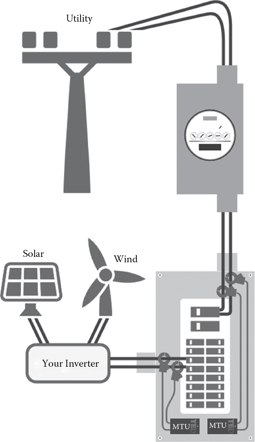
TED system monitoring the utility power and inverter output power (Courtesy of Energy, Inc.).

□ What is the maximum operating temperature for the SB3000US in MPP mode? _____
□ What is the average maximum daily temperature for the zip code? _______ (http://www.weather.com/weather/climatology/monthly)
12.5.4 Checking for Minimum Start Voltage
We now need to understand whether or not the temperature-corrected operating voltage, Vmp, is greater than the minimum start voltage; otherwise, the inverter will not turn on. The data sheet for the PV module MAY NOT include a temperature coefficient for Vmp. In this case, use the temperature correction for Voc. Using the average maximum daily temperature, correct Vmp:
□ What is the maximum monthly average minimum temperature? ______ (°F) ______ (°C)
□ What is value of Vmp @ STC? _____ V
□ What is the temperature correction factor for Vmp for this module? ______ V/C
□ What is the value of Vmp at the average daily temperature? ______ V
□ What is the temperature correction value for Vmp for the string? ______ V/C
□ What is minimum start voltage? _____ V
□ Is this value of Vmp greater than the minimum MMP start voltage? _____ Yes _____ No If no, what can be done to increase the value of Vmp?
□ What is the maximum input voltage for MPP operation? _____ V
□ Is the temperature-corrected Vmp greater than the maximum MPP voltage? _____ Yes _____ No
□ If yes, reduce the number of PV modules per string and possibly increase the number of strings, while keeping the total number of modules close to the design requirement.
□ If yes, what is the new value of PV modules per string _____ and the total number of strings? _____
12.6 Monitoring
We will employ the TED monitoring system, which measures real-time power flow in the customer’s electrical system. TED can make up to 32 separate circuit measurements, including the PV system output circuit and the utility feed, as well as other branch circuits (i.e., customer loads). In our case, we will use TED to measure
- The power flow from the inverter into the customer’s service panel (PPV)
- The power flow at the utility point of connection into (or out of) the same service panel (PUTIL)
Since TED measures the magnitude and direction of power flow, it can also calculate the total (“vector sum”) of the power consumed by the branch circuits (PLOADS) and the PV system; that is,
PUTIL=PLOADS−PPV or PLOADS=PUTIL+PPV
When the PUTIL is positive, the power consumed by the loads is greater than the power generated by the PV system. When the power flow is negative, the power generated by the PV system is greater than the power consumed by the loads.
How does TED accomplish this task? TED is based on two sensors: a voltage sensor and two current transformers that measure the current flowing in the L1 and L2 legs of a 240 V circuit. In this manner, TED can measure the instantaneous power flowing in the circuit, including the direction of the power flow in the circuit. Figure 12.1 shows the case where the utility power and the PV system output power are both being measured. Wiring TED into the PV system and setting up TED will be discussed in Section 12.12.
12.7 Four-Line and Single-Line Diagrams for the String Inverter System
As in Chapter 11, we will now develop a four-line diagram. Make sure to include the following:
- PV module
- Junction box (on the roof, if required)
- PV combiner box with overcurrent protection (if required)
- DC disconnect (manufacturer and model number)
- Wire gauge and type for all DC (PV) runs
- Conduit from roof junction box to inverter, including wire gauge and type
- Inverter
- Production meter
- AC disconnect
- PV breakers in service panel
- Conductor and conduit (or cable) used to connect to the inverter, production meter, AC disconnect, and service panel
- Ground electrode
- Ground electrode conductor
- Equipment grounding conductors
Record the following information as annotations:
□ Type (e.g., THWN-2) and size (e.g., 10 AWG) of all current-carrying and grounding conductors and conduit, or type and size of cable, calculating the ampacity of wire taking into account corrections for cloud bounce, continuous duty, operating temperature, and number of current-carrying conductors in conduit
□ Markings affixed to conductors and conduit, or cable
□ Make and model of the PV modules
□ Make and model of the microinverters
□ Record the AC cable run (in this case the Enphase Engage cable) between drop connectors and from last drop connector to the on-roof junction box: _____ .
□ Record the other AC wiring _____ and conduit _____ to be used from the roof-junction box to the AC disconnect and to the production meter.
□ Record the other AC wiring _____ and conduit _____ to be used from the production meter to AC disconnect.
□ Record the other AC wiring _____ and conduit _____ to be used from the AC disconnect to the service panel.
□ Confirm compatibility of PV module and inverter. This should include:
□ Maximum source voltage (input voltage to inverter) at coldest temperature recorded at site in the past 30 years: _____ V.
□ Minimum operating source voltage (input voltage to inverter) at average high daily temperature at the site: _____ V.
□ Specify the WEEB™ grounding clips used: _____ .
□ Specify equipment grounding conductors: _____ , _____ , and _____ .
□ Specify system grounding electrode conductor: _____ .
□ Specify grounding electrode: _____ .
□ Specify customer service panel, including manufacturer _____ , model number _____ , ampacity of main disconnect _____ , ampacity of panel rails _____ , and size of PV system breaker _____ .
□ Calculate the maximum permissible ampacity of photovoltaic system breakers (from 120% rule): _____ .
□ Specify the details of the subpanel (if necessary): _____ .
□ Specify main service panel, including manufacturer _____ , model number _____ , ampacity of main disconnect _____ , ampacity of panel rails _____ , and actual size of PV system breaker _____ .
Include the following information as annotations:
□ Markings (i.e., labels) affixed to conductors and conduit, or cable
□ Markings affixed to equipment
□ Specify customer service panel; calculate the maximum permissible ampacity of photovoltaic system breakers (from 120% rule): _____ .
□ Is there room in the panel board to accommodate the back-fed breakers from the PV system? _____ ? If not, come up with a solution. Solutions may include one use of “twin” or “quad” breakers or may require the use of a sub-panel or even a new main service panel.
12.8 Modifying the Mechanical Subsystem
As mentioned before, we will use the same physical layout as in Chapter 11. We will need to remove the microinverters from the system and, in their place, we will wire the modules together into series strings.
The RNG-240D PV module comes with two cables approximately 36 in. long with MC-4 connectors, the PV positive and negative connections. Each string of PV modules will need a pair of “home runs” fabricated out of USE-2 or PV wire to bring the PV input circuit to a junction or combiner box.
In the case of a single string, we will use a junction box (Figure 12.2) to make a transition from USE-2 or PV wire to 90°C rated wire such as THHN or THWN-2 using a simple splice. Figure 12.3 shows the splices used to connect the two wire types.
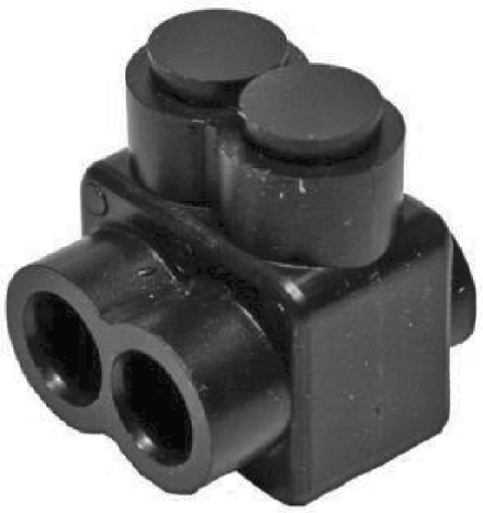
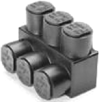
In the case of two strings, two source circuits will need to be wired together with the THHN/THWN-2 wire in a junction box. In this case, we simply use a splice that can accommodate three wires. See Figure 12.4.
In the case of three or more source circuits, we will need to use a combiner box and protect the positive lead of each source circuit with overcurrent protection, usually a DC-rated circuit breaker. Figure 12.5 shows a combiner box with six circuit breakers, a negative buss (left), and a ground buss (right).

Combiner box showing circuit breakers for six PV source circuits, negative and ground busses (Courtesy of Midnite Solar, Inc.).
The breaker current rating is specified by the PV module manufacturer and is usually listed on the back of the module as the “maximum series fuse rating.”
In our case, however, we have only a single string or at most two strings and will not need the combiner box, just a junction box. Assuming that we are starting with a PV system using microinverters, the following tasks need to be accomplished:
□ Remove all modules, WEEB clips, and module clamps.
□ Remove Enphase microinverters and Engage cable.
□ Replace the modules, WEEB clips, and module clamps, following the instructions in Chapter 11.
□ Wire the PV modules together as you go, using the MC-4 locking connectors. Use wire management clips to take up any slack in the PV cable so that the cable does not touch the roof.
□ Sketch the location of the junction box on the roof. A good location for the junction box is under a PV module and at a point convenient for penetration of the attic space.
□ Measure the distance from the first and last PV modules in the string to this junction box.
□ Make up two home runs—one for the negative lead of the last PV module and one for the positive of the first PV module, using these distance measurements. Only one end of this cable needs a connector, as the other end will enter the junction box and be terminated with a splice.
12.9 Attic Penetration
We need to carry the PV output circuit to the DC disconnect and inverter. As mentioned before, most of this run may be made in the attic space of the house. In this case, a penetration of the attic may have already been made in the last laboratory.
Again, we will use a waterproof junction box and 1 in. rigid conduit, and we will flash this penetration with the same technique as we did for flashing the footings in Chapter 11. Once inside the attic, we can make a transition to EMT (electrical metallic tubing), flexible metal conduit (FMC), or MC cable.
At the end of the attic run, the exterior wall of the building will be penetrated and a vertical run can be made down to the DC disconnect and inverter. This final external vertical run is usually made in EMT.
Starting with the j-box in the attic, make the DC run to the DC disconnect. Document the wire, cable, and conduit used:
□ From the attic j-box to the point of penetration of the exterior wall: _____
□ From the exterior wall to the DC disconnect of the inverter: _____
12.10 Installing Balance of System
□ Starting with the output of the inverter, install conduit from the inverter to the production meter enclosure.
□ Install conduit from the production meter enclosure to the AC disconnect.
□ Install conduit from the AC disconnect to the breakers back-feeding the main service panel.
Using the FLD as a guide, use wire of appropriate ampacity and type rating for the environmental conditions:
□ Wire from the attic junction box to the DC disconnect.
□ Wire from the inverter to the production meter to the AC disconnect.
□ Wire from the AC disconnect to the dedicated back-feeding breakers in the service panel.
□ Install production meter and lock ring.
Note
In areas that are chronically damp (e.g., within 3 miles of a large body of water), the authorities having jurisdiction (AHJs) may require the use of PVC schedule 80 conduit on outdoor (but not attic) and wet-rated wire (e.g., THWN-2) for the outdoor runs.
12.11 Lightning and Surge Protection
At this point in time, lightning and surge protection devices may be deployed at the DC disconnect and AC disconnects.
See the manufacturers’ instructions for installation instructions.
12.12 Installing the TED Monitoring System
All of the work in this section must be carried out using the following personal protective equipment:
- Electrical gloves
- Face shield
12.12.1 Preparing the Main Service Panel
□ Switch off the main disconnect. This will de-energize the panel board.
□ If possible, remove the security ring and unplug the utility meter. This will de-energize the wiring from the output jaws of the meter socket to the main disconnect. Doing so may require the permission of the utility company.
□ Remove the cover to the panel board.
□ The instructor will create access to the L1 and L2 feeds from the utility meter to the panel board. Caution: if it is not possible to remove the utility meter, the utility wiring is not de-energized and extreme care needs to be taken when working in the vicinity of this wiring. In any event, only the instructor will work with this circuit.
12.12.2 Installing the MTU and Current Transformers
□ The instructor will measure and record the line voltage at the service panel: _____ VAC. This voltage needs to be within 216 to 264 VAC (for 240/120 V split phase service).
□ Record the serial number of the MTU: _____ .
□ Connect the black and red wires to spare L1 and L2 circuit breakers. It is a violation of the NEC to “double load” circuit breakers. You may be lucky enough to be permitted to “piggyback” your wiring onto a circuit breaker servicing an existing branch circuit by the AHJ.
Later, if deemed necessary due to low signal strength conditions, the red wire may be removed and covered with electrical tape.
□ The current transformers are now installed on the L1 and L2 conductors leading from the output jaws of the meter socket to the main disconnect. Make sure the red dots on the CTs are pointing toward the meter jaws.
□ Install current transformers on the L1 and L2 conductors from the SB3000US inverter.
□ Connect the CTs to the MTUs using the cable provided. Note that plugs on this cable are polarized.
□ Attach the MTU to the inside of the service panel using the double-sided tape (provided) or sheet metal screws.
□ Plug the utility meter back in, install the security ring, and turn on the main disconnect.
The MTU will blink approximately 10 times when power is first applied.
12.12.3 Installing the Gateway
□ Plug the gateway into a dedicated 120 V outlet. If there is other electric equipment on this branch circuit, it may be necessary to install a filter, which comes with the TED system.
The gateway will blink approximately five times when power is first applied.
□ Plug an Ethernet cable into the gateway and plug the other end of the cable into the Internet router
12.12.4 Remote Display
□ Plug the display power supply into a 120 V outlet, plug the power supply cable into the back of the display charging stand, and insert the display into the display charging stand.
□ After 15 seconds remove the display and reinsert it back into the stand. The display will be fully charged in 24 hours.
□ Record the display ID code: ___________ .
12.12.5 Footprints Software Setup
The TED system can be configured and monitored via a browser interface (IE, Firefox, Chrome, or Safari).
□ Download the TED 5000 installation instructions and install the software.
□ Open a browser window and type in the following URL: http://TED5000.
This will open the Footprints software program and allow us to configure the TED hardware. We will configure two MTUs:
□ Click on the Edit tab.
□ Choose “System Setting Software” at the top of the Footprints screen.
□ Click on the “System Layout” tab.
□ Enter two MTUs and one display.
□ Set display voltage as 240 V and MTU connection type as “120/240V(BK, WH, RD)” for both MTU 1 and MTU 2.
□ Check that you would like to modify the MTU configuration: “Yes.”
□ Configure MTU 1 to be “Adjusted Load.”
□ Configure MTU 2 to be “Generation.”
□ Click on the “Product Identification” tab and enter the following IDs and descriptions:
□ MTU 1 ID: ___________ ; description: Utility
□ MTU 2 ID: ___________ ; description: PV System
□ Display product: _____ .
□ Click “Next” and fill in “Operational Settings.”
□ Click “Next” and fill in “Display Settings.”
□ Click “Next” and fill in “Footprint Settings.”
□ Click “Next” and click “Update” under “Apply Setting to the Gateway.”
□ Click “Finish.”
The TED dashboard should now display the power in the two circuits—PV and utility feed.
12.13 Certification Testing
Once the system is up and real-time data can be seen displayed on the dashboard, it is time to fill out the certification sheet.
The following information needs to be recorded on the certification sheet (Figure 12.6):
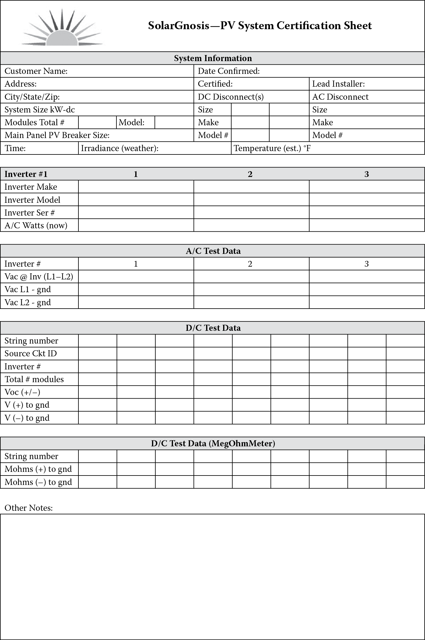
□ Customer name, address, system size
□ Date of certification, person performing certification, lead installer
□ Time, irradiance perpendicular to modules, ambient temperature
□ Model number of DC and AC disconnects; modules
□ Model number of PV breaker and ampacity
□ Inverter(s) model number
□ AC watts now for each inverter
□ Vac L1 neutral, Vac L2 neutral
□ Vac L1 ground (gnd), Vac L1 gnd
□ PV input circuit (string) details: Voc (±), V(+) to gnd, V(–) to gnd
12.14 Troubleshooting
The instructor may at this point introduce one or more system faults. These faults may be indicated by the inverter LEDs and or error codes.
One commonly encountered system fault involves a blown GFCI 1 A fuse at the input of the inverter. The instructor can replace a good fuse with a blown fuse and create a ground fault on one of the PV input circuits.
□ Observe the middle (B) LED. If it is glowing red, there is a ground fault. Perform appropriate troubleshooting procedures.
□ Observe the bottom (C) LED. If it glows yellow for 5 s, goes out for 3 s, and then blinks twice, there is a grid failure. Check the grid voltage and frequency to see if it is within specification.
Other error codes are documented in the SB3000 US Installation Guide, Chapter 10, “Troubleshooting.”
It will be up to individual instructors to fashion other troubleshooting exercises.