6
Application Methods
The efficient use of coatings depends, apart from a proper chemistry that should result in the proper properties, also on the application methods. These methods are varied and depend on the application purpose. Several of them are used on laboratory scale as well as on industrial scale. In this chapter we discuss, necessarily briefly, the most important of these methods, starting with those for depositing conventional paints and thereafter treat some more advanced methods. This chapter concludes with an overview of a typical modern coating application, namely, automotive coatings.
6.1 Conventional Deposition Techniques
For paints the usual application methods are brushing, rolling, and spraying. In the next sections we deal with these techniques, for which [1] is a used as a guide.
6.1.1 Brushing and Rolling
The classical technique to apply a coating is brushing. Brushes are available in a wide range of shapes and type of bristles. The paint is picked up by and held between the bristles; the pressure applied to the brush presses the paint out from between the bristles. The viscosity range of paints is typically 0.1–0.3 Pa s. If the viscosity is too low, too little paint will be on the brush, making dripping easy. If the viscosity is too high, too much paint will be brought out of the container, making brushing more difficult. A wide range of shear rates is involved. During pickup the shear rate is relatively low, say, 15–30 s−1, but during brushing, it is in the range of 5 × 10³–20 × 103 s−1. In application the surface of the wet film shows line of smaller and larger thickness, the so‐called brush marks. Evidently they do not arise from the individual bristles as their spacing is too wide for that, but they appear from irregularities in the wet film thickness that occur during the separation of the paint from the brush and change to lines by the movement of the brush. These marks should disappear in relatively short time by having a proper balance between the driving force, the surface tension, and the resistance, as in a later stage the viscosity will become too high.
Rolling is a fast method for hand application method, for which a wide variety of rollers is available. The viscosity requirements are similar to that for brushing. During rolling at the point of contact, a pressure is present and is released after moving the roller, leading to cavitation, that is, the formation of small bubbles. During further movement of the roller, these bubbles extend, the walls between them become fiber‐like, and they eventually break. This may lead to marks similar to brush marks. The process also leads to droplets of loose paint to split off, that is, to spattering, which can occur with almost any paint but is particularly prone in latex paints.
6.1.2 Spraying
Spray coating is a rather descriptive name: a paint is transported to a (typically air pressurized) nozzle where it is (in the usual jargon) atomized, that is, dispersed to droplets that are sprayed on the substrate at a certain distance. This requires a relatively low viscosity, say, η ≅ 0.05–0.15 Pa s. It is much faster than brushing or rolling and especially suitable for somewhat irregularly shaped surfaces, but is more difficult to control and leads to a lower deposition efficiency, as only a fraction of the droplets is deposited on the substrate (overspray) and some of the droplets bounce back (spray dust). For several applications electrostatic spraying is used in which the deposition process is enhanced by using charged droplets and an electric field between the nozzle and the object, so that the droplets are accelerated during their flight to the object. If the resin is too viscous, hot spraying may be used. For conventional compressed air spray, the deposition efficiency may be as low as 25%, while for electrostatic spray it may be as high as 85–95%. However, the efficiency is influenced heavily by the shape of the substrate: a low efficiency can be expected for a fence, while a much higher efficiency can be for a flat wall. The film morphology is controlled by:
- Type (hydraulic or pneumatic) and geometry of the nozzle (for pneumatic, internal, or external mixing).
- Air pressure.
- Solution viscosity.
- Solvent properties (evaporation rate).
- Distance between nozzle and substrate.
Moreover, spray dust may land on the wet surface and, if the surface tension of the droplet is different from the wet film, may lead to cratering.
The oldest type of spray gun is the compressed air spray gun in which the paint is transported by a low pressure (1–5 kPa) to the orifice where it is atomized by compressed air with a pressure of about 250–500 kPa, that is, dispersed to droplets with a typical droplet size of 20–50 μm. The atomization process is controlled by:
- The viscosity η (the higher the η, the larger the droplet size).
- The air pressure (the larger the pressure, the smaller the droplet size).
- The diameter of the orifice (the smaller the diameter, the smaller the droplet size).
- The paint transport pressure (the higher the pressure, the smaller the droplet size).
- The surface tension γ (the lower the γ, the smaller the droplet size).
The deposition efficiency can be improved by using a high volume low pressure air gun in which a lower pressure is used (20–70 kPa), but with larger air volumes, thereby reducing bounce back. An alternative is the low volume low pressure air gun, which also uses a low pressure, but the air volume is reduced by mixing the paint and air inside the gun. Another type is the airless spray gun in which the paint is pressed out of the orifice at relatively high pressure, 5–35 MPa, leading to a droplet size typically between 70 and 150 μm. For all types of guns, one can use the single pass technique, in which droplets merge on the substrate into a full wet film before drying to smooth films, or the multiple pass technique in which droplets dry independently, usually resulting in a rough film, but wettability issues can be overcome. Generally, large areas can be covered with, depending on the application at hand, a homogeneity that can be considered as good or bad.
As indicated above, electrostatic spraying can be used to enhance the deposition efficiency. An electrode is built in the gun on which a voltage typically between 50 and 125 kV is put; the air passing the electrode is ionized and charges the droplets. Upon arrival of the (earthed) substrate, the droplets discharge. The electric field distribution causes the droplets to attach not only to the front of the substrate but also to the back side (with obvious restrictions). This wraparound effect reduces overspray and can lead to a deposition efficiency as high as 80%. Evidently, the charge pickup is controlled by the conductivity of the paint: a too low conductivity leads to insufficient charge pickup, while a too high conductivity leads to electrical shorting. The optimum overall resistance varies for different electrostatic spray guns but ranges from 0.05 to 20 MΩ. Because the conductivity of waterborne coatings is much higher, a lower overall resistance can be used, down to 0.01 MΩ, but typically a specially designed equipment with an electrically isolated coating line. Electrostatic spraying is the most important deposition method for powder coatings but suffers from some drawbacks. Obviously, the substrate must not be only conductive, but this leads for recessed areas also to a largely diminished electric field strength (Faraday cage‐like areas) that therefore may be difficult to spray.
Hot spraying can be used not only for resins with a too high viscosity but also to reduce the use of solvents. Consequently, the technique is particularly useful for high‐solids coatings. A temperature of 40–65 °C is typically used. The method requires a specially designed gun that keeps the paint circulating, even when the gun is turned off.
Finally, one can also use a slot (coating head) instead of an orifice (nozzle) so that the paint flows out as a continuous curtain, and, consequently, the technique is called curtain coating. The substrate moves under the curtain with a conveyor belt. The curtain should be wide to avoid edge defects, but this leads to overflow for which a recirculating system is required. As no paint separation (film splitting) occurs, the film laid down is essentially smooth and the thickness can be rather uniform.
6.2 Laboratory and Industrial Methods
Apart from the deposition methods for conventional paints, deposition of advanced coatings can be done in various other ways. Some of these methods can be used in both a laboratory and a factory, but others are typically limited to either laboratory or factory. Laboratory methods include drop casting, doctor blade coating, spin coating, and spray coating. Typical factory methods are dip coating and spray coating. As discussed in the previous section, for paints brushing, rolling, and spraying are frequently used methods. It should be noted that methods of restricted interest in coating technology are not necessarily of restricted interest in general. For example, doctor blade technology is relatively lightweight in coating technology, but a heavyweight in printing. In the sequel of this section, we discuss the methods mainly used in the laboratory and their industrial counterparts, while in the subsequent section we deal similarly with mainly industrially used application methods.
Probably the simplest laboratory method is drop casting, in which a droplet of the coating solution1 is put on the substrate and thereafter, possibly, is distributed over the substrate. Evidently, only relatively small areas can be coated. Furthermore, the process is uncontrolled and hence leads to variable thickness over the film. However, it is frequently used for rapid screening, as there is no waste of material.
6.2.1 Doctor Blade Coating
Doctor blade coating, also known as knife or blade coating, is a processing method for the fabrication of large area films on rigid or flexible substrates. The coating solution is put in (a reservoir) in front of a knife edge (blade) that is moving with respect to the substrate. For lab‐scale processing the blade is moved over a flat surface, while for large‐scale roll‐to‐roll processes, the blade is fixed over the moving substrate (Figure 6.1a). Relatively large areas can be coated with good uniformity and no waste of material. The thickness of a doctor blade film L depends on the viscosity η of the solution (codetermined by the solid content of the solution), the speed of drawing v, and the gap height h, that is, the opening between the knife edge and the substrate. The viscosity depends on the solid content of the solution. The speed used is typically 0.2–5 cm s−1, while typical thicknesses are 10–50 μm. The final wet layer thickness is roughly half of the gap width depending on the coating speed and flow behavior [2]. Further coating parameters that influence the film formation are surface energy of the substrate, surface tension of the fluid, and surface temperature. The thickness of the film can be estimated from first principles, as done by Chou et al. for ceramic dispersions [3] and later by Tok et al. [4]. These authors assumed Newtonian flow for the dispersion, and by applying the solutions of Stokes equation for pressure and Couette flow, they obtained
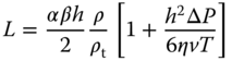
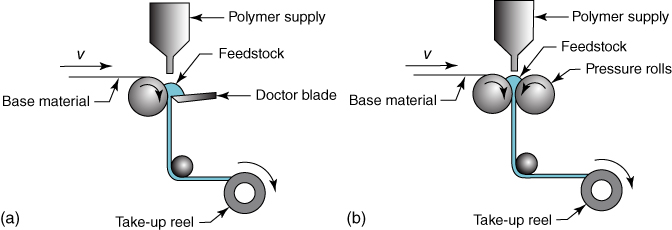
Figure 6.1 Planar coating processes. (a) Doctor blade coating; (b) Roll method.
where T is the length of the knife, ΔP the pressure difference, ρ the density of the dispersion, and ρt the density of the dry film. The width correction factor α takes into account that the as‐deposited film flows sideward. It is expected to be close to one for wide knives. The packing correction factor β corrects for the weight loss during drying and is expected to be close to 0.6, the volume fraction for close packing. Neither ceramic slurries nor polymer solutions generally behave as Newtonian fluids, but modeling for non‐Newtonian flow has been addressed by Ring [5] and Huang et al. [6]. An overview of the doctor blade method for optical photovoltaic (OPV) fabrication of organic solar cells for energy production is given by Hösel [7].
Instead of a doctor blade, also an applicator roll can be used (Figure 6.1b), so that the polymer coating material is squeezed against the substrate by means of two opposing rolls, one the pressure roll and the other the applicator roll. This process is called roll coating and is mainly used in industrial applications, typically applying the paint on a metal foil of varying thickness. A more sophisticated form employs a reservoir containing the paint through which a so‐called fountain roll is rotating. The fountain roll deposits the paint another roll, the feed roll, which on its turn transports the paint to the applicator roll. By inserting still another roll that reverses the surfaces of the foils and another set of deposition rolls, one obtains reverse roll coating in which both sides of a planar substrate can be coated.
6.2.2 Spin Coating
In spin coating a droplet of the coating solution is put at the center of a spinning substrate (Figure 6.2a). With this method relatively thin layers result, say, below 1 μm down to as low as 10 nm. In spin coating the thickness is controlled by the time of spinning and the angular velocity of the spinner, and the viscosity, and therefore the concentration of the solution. Typical rotation rates are between 500 and 104 rpm (revolutions per minute), which can be programmed depending on the stage of spinning. The higher the rotation rate and the lower the viscosity, the thinner the film. Good uniformity and reproducibility can be achieved, as well as good control over the thickness of the deposited layer. As spinning is limited to relatively small‐sized objects, large area coverage is a problem, as is the waste of the coating solution used. Generally, a film dries fast so that there is limited time for ordering of the molecular components. Thermal annealing afterward is used to remedy this, if required. The method is used intensively in photolithography, to deposit layers of photoresist about 1 μm thick, typically spun at 1200–5000 rpm for 30–60 s. A concise review of spin coating is given in [8].

Figure 6.2 Spin coating. (a) Principle; (b) Processes involved.
During spinning, the solvent evaporates at a rate dependent on the rotation speed (Figure 6.2b). Hence, concentrations change during the process. A simplified model is proposed by Meyerhofer [9] in which the spin‐off and evaporation stages are taken to be sequential. This model was used by Bornside et al. [10] with a Carreau‐like model using for the viscosity of PMMA/chlorobenzene solutions reading
Here the high shear rate viscosity η∞ and low shear rate viscosity η0 are functions of the concentration, while ![]() denotes the shear rate and λ and n are parameters. The agreement with experiment appeared to be good, but such a model is capable of describing film thicknesses relatively accurately only at the expense of determining a relatively large number of parameters. However, such a model underpredicts the film thickness for cases in which a very volatile solvent is used or the initial concentration of polymer is high while overpredicting the film thickness for cases in which a low volatility solvent is used or the initial polymer concentration is very low. These deviations are a consequence of how the model decouples fluid flow and solvent evaporation. Hence it appears that in the limit of small evaporation and small initial solute concentration, the assumption that the evaporation dominates the process for a significant time interval is incorrect, as analyzed by Cregan and O'Brien [11, 12].
denotes the shear rate and λ and n are parameters. The agreement with experiment appeared to be good, but such a model is capable of describing film thicknesses relatively accurately only at the expense of determining a relatively large number of parameters. However, such a model underpredicts the film thickness for cases in which a very volatile solvent is used or the initial concentration of polymer is high while overpredicting the film thickness for cases in which a low volatility solvent is used or the initial polymer concentration is very low. These deviations are a consequence of how the model decouples fluid flow and solvent evaporation. Hence it appears that in the limit of small evaporation and small initial solute concentration, the assumption that the evaporation dominates the process for a significant time interval is incorrect, as analyzed by Cregan and O'Brien [11, 12].
Spin coating over a small sinusoidal topography was studied by Hayes and O'Brien [13]. Despite the fact that the basic flow is radial, the final liquid coating does not have radial variation, but varies according to the underlying topography.
6.2.3 Dip Coating
Dip coating does just what the name says: the object to be coated is dipped in a coating solution, either partially or completely, and thereafter withdrawn, generally with a controlled speed. The technique is used for advanced coatings, for example, window coatings and simple applications, such as providing a coating on the handles of (steel) tools. After withdrawal, a film is attached to the part that is then dried and/or cured. The method is used in both laboratory and factory (Figure 6.3). It is a particularly useful method to coat large flat areas, complex shaped objects for which otherwise no complete coverage can be realized, and flexible substrates. Flexible laminar substrates can be dip coated using a continuous roll‐to‐roll process. For flat areas the withdrawal speed, the withdrawal angle, and the viscosity and surface tension of the solution control the thickness of the final film. A drawback for flat objects is that both sides are coated, albeit with good uniformity and controlled thickness. Also a lot of raw material is generally wasted. Dip coating, while excellent for producing high‐quality, uniform coatings, requires precise control and a clean environment, as the applied coating may remain wet for several minutes until the solvent has evaporated. The drying process can be accelerated by heating. In addition, the coating may be cured by a thermal, UV, or IR treatment, depending on the coating solution formulation. Once a layer is cured, another layer may be applied on top of it with another dip coating/curing process. In this way, multilayer stacks can be constructed. Brinker has given a review on dip coating, in particular dealing with sol–gel coatings [14].

Figure 6.3 Dip coating. (a) Laboratory dip coating; (b) Continuous dip coating. (1) Reel with substrate; (2) substrate; (3) bath; (4) paint of coating formulation; (5) guiding rolls; (6) oven; (7) wipers; (8) excess paint; (9) coated substrate.
The thickness L is determined by the balance of forces at the liquid–substrate interface and is given approximately by the Landau–Levich equation, reading
where v is the withdrawal speed, g the acceleration of gravity, η the liquid viscosity, ρ the liquid density, and γ the surface tension of the liquid.
The dip‐coating process is a versatile technique because it results in a range of coating thickness with reasonable coating quality and a coverage uniformity of about 10%. The equipment is inexpensive and relatively simple to operate, while the high speed capability of the process can lead to low costs and high productivity. Moreover, scale‐up from laboratory coaters is relatively easy, and excess coating material can be removed by doctoring devices such as a Mayer rod, an air knife, blades, or squeegee rolls, of course, properly avoiding pollution of the excess solution. Typically, the range of operating parameters for dip coating are a viscosity of 20–2000 cP (or mPa s), a wet thickness of 10–200 μm, and a line speed 0.5–7.5 m s−1. When thin coatings are required at high speeds meanwhile using high viscosity, a doctoring device is needed to obtain the desired coverage and thicknesses.
A review on dip coating is provided by Grosso [15], and Yimsiri and Mackley [16] provide a comparison between the spin‐coating and dip‐coating processes for light emitting polymers.
6.3 Powder Coating
As discussed in Chapter 4, there is a drive to avoid the emission of volatile organic compounds (VOCs). One way to avoid emission of VOCs altogether is to avoid solvents during coating application. Powder coatings provide this option, as they are ready paints, but in powder form. They are sprayed with electrostatic charge onto (usually) earthed metal surfaces, subsequently heated in oven so that the powder particles can coalescence, wet the substrate, and level to a film of even thickness (Figure 6.4b). The film formation stages comprise softening and rounding of the particles, after which they sinter together and coalesce, meanwhile wetting the substrate (Figure 6.4a). Thereafter these films are cured. Films with a thickness up to 500 μm can be realized.

Figure 6.4 Powder coatings. (a) Schematic representation of the leveling process; (b) Image of the spraying process; (c) Electrical field lines enabling covering of edges; (d) Schematic representation of a powder coating setup.
Advantages of powder coatings are several. One could consider such paints as frozen 2K systems, as the polymers involved normally have a relatively high Tg (45–60 °C) so that the component can be mixed without reacting and resulting in a semi‐1K system. This implies, though, that a catalyst has to be used. There is also the possibility to recycle the overspray so that a 100% transfer efficiency of the powder results. In this recycling process the powder particles remain unchanged, contrary to solvent‐ or waterborne systems. In the latter case spraying slightly changes the droplet compositions, and they become incompatible with the “virgin” paint composition. As the nonrecyclable overspray easily amounts to 30–50%, this constitutes chemical waste. Another advantage is that excellent coverage of complex 3D shapes can be realized. The powder particles follow the electrical potential field lines, even to the backside, and consequently edges are covered (Figure 6.4c). Normally a good adhesion to the metal results as the metal has a direct interaction with the resin with no solvents at the interface interfering. Finally, normally the final coating has good mechanical properties since no residual stresses from solvent evaporation arise but only from thermal expansion differences. A schematic picture of the process is shown in Figure 6.4d.
Flow and cure are simultaneous temperature‐driven phenomena. On the one hand, due to flow, wetting, coalescence, film formation, and leveling occurs, all driven by surface tension. On the other hand, curing leads to network formation and increases the viscosity, inhibiting the abovementioned steps. Hence, a balance in time and temperature is required2, and this leads to a flow and cure window (Figure 6.5a). Flow starts at t = 0 and largely stops at the onset of the cure, that is, at the gel point. Thereafter the cure sets in, continuing until the final temperature is reached. The extent of both stages can be assessed by dynamic mechanical analysis (DMA). An example is shown in Figure 6.5b, which are the absence of cure without catalyst, a decent flow window with having 0.25 mass% catalyst, and troublesome to impossible flow for 0.5 mass% and 1.0 mass% catalyst, respectively.
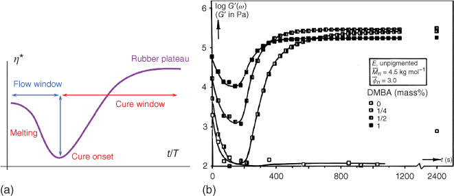
Figure 6.5 Flow and cure during heating. (a) Schematic representation showing the flow and cure window; (b) DMA result showing G′ for a resin and various amounts of crosslinking catalyst DMBA.
To decouple flow and cure, one can try to encapsulate the crosslinker in a core–shell particle so that flow of the main resin can occur at a relatively low temperature and crosslinking only at a somewhat higher temperature after the shell material has been molten and/or dissolved in the matrix. This is beneficial for application on heat‐sensitive materials, like wood. An example is provided by spray drying an emulsion of a liquid crosslinker, epoxidized linseed oil (ELO), in an aqueous solution of a high Tg polymer, poly(N‐vinyl‐2‐pyrrolidone) (PVP) as encapsulating material [17]. The choice of PVP was based on the fact that its melting, between 54 and 175 °C depending on Mw, can be used as a temperature trigger for release of the core material into the powder coating matrix at typically 110 °C. A free‐flowing powder was obtained with a payload of ≅20 wt% and a high efficiency of encapsulation of ≅85%. Figure 6.6 shows the resulting capsules. Use of such a melting trigger could ultimately lead to the development of powder coatings that can be cured at much lower temperatures than the conventional curing temperature of ≈180 °C.
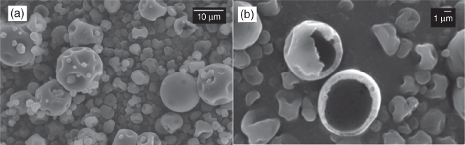
Figure 6.6 Encapsulated crosslinker for powder coatings. (a) Overview showing the capsules obtained; (b) Detail showing two broken capsules illustrating their core–shell nature.
A characteristic defect of powder coatings is the “orange peel” effect, resulting from charge and/or density distributions in the powder particle layer, combined with insufficient flow. This effect results in a waviness in the surface with a wavelength λ typically of 2–5 mm, visible to the human eye, and should not be confused with loss of “gloss” that refers to the total reflectance over an angle 20–60° and is affected mostly by short wavelength waviness. The orange peel effect is clearly visible in reflectance (distinctness of image), as shown in Figure 6.7.
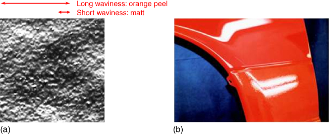
Figure 6.7 Orange peel effect. (a) Image of the surface showing long and short wavelength ondulations; (b) Reflection of a lamp on a coating showing with the orange peel up (lower reflection) while still being glossy (upper reflection).
The powder coating production process consists of several stages. First, the mixing of all the ingredients, that is, the resin (with a Tg typically of 50–70 °C), the crosslinker (which be must be a solid for handling), the pigment, and the additives (often a wetting and degassing agent). Such a mixture typically contains 45% binder, 45% pigment, 7% crosslinker, and 3% additives. The second step is mixing at a temperature above the Tg of the resin, typically 90–110 °C, in an extruder. At this temperature the mixtures still has a high viscosity, and high shear is needed for optimal pigment dispersion. The residence time is typically 20–30 s, as a slight prereaction will occur (2–10% conversion of reactive groups, depending on the system used). After the extrudate is cooled down, it is crushed and milled to the required particle size, which is dependent on the application, but is typically in the range of 50–100 μm. The whole process is illustrated in Figure 6.8.
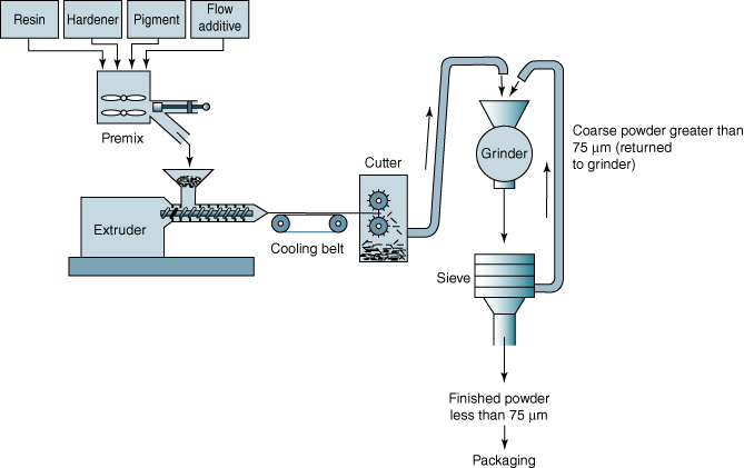
Figure 6.8 Schematic representation of the powder coating production process.
Powder coatings are generally applied on complex 3D metal shapes that need a complete coverage by the paint. These can be found in domestic appliances, such as, whitegoods (high quality), furniture frames, and garden machines. They are also applied as architectural coatings, for example, in window frames and as industrial coatings, for example, on pipes and on shutters. Another use is in transport, where coating of bicycle frames and the use in some automotive primer surfacer coatings are good examples.
There is a trend toward low temperature cure. The cure window currently in use is typically 10 min at 200 °C, possibly adjusted to 15 min at 180 °C. Desired applications, however, are composed of heat‐sensitive substrates, such as wood and plastic. Here the window is reduced to, say, 10 min at 90–120 °C, and radiation curing is a solution in this case (see Section 4.4). It would also be desired to save energy in connection with applications as metal coatings. Here 10 min at 150 °C is aimed for. To these purposes newly designed systems will have to be introduced.
Low temperature curing poses some challenges. First and foremost, the rheology will be influenced. On the one hand, one wants to maintain the Tg of the resin and paint to have, respectively, physically stable and free‐flowing powders. On the other hand, the viscosity should decrease in order to be able to flow at lower temperature. Second, one needs a proper balance between extrusion stability and cure window. One also requires chemical stability, as the prereaction in the extruder (>60 °C) must be kept minimal (≪ gel point) for good flow, but in order to cure at lower temperature, the reactivity must increase. Third, also storage stability is important. Chemical stability is required as no prereaction should occur during storage, say, for 4 months at maximum 40 °C, and, hence, if the chemical reactivity increases too much, the “frozen 1K” system concept is no longer sufficient.
6.4 An Example: Automotive Coatings
A familiar type of advanced coatings is the automotive coatings. These types of coatings are realized in a highly automated or robotized factory in which humans are mainly involved in inspection and the occasional rework that has to be done after the occurrence of a defect, for example, the presence of a dust particle in the coating that ruins its overall shiny appearance. On the total coating system, generally a 10‐year warranty is put with respect to corrosion protection of the metal carcass and with respect to weathering of the coating. As the car carcass is a rather complex 3D object, the conventional deposition processes are not suitable, and one “simply” immerses the complete carcass in a paint bath in order for the paint to be able to reach all corners and crevices (Figure 6.9).

Figure 6.9 Automotive coating. (a) Simplified schematic image of coating a car; (b) Photograph of visual inspection of the downside of a car after painting.
Automotive coating systems contain several layers. Before coating, the (usually) steel carcass is cleaned after which the (inevitable) oxide layer is stabilized by phosphatizing the steel. The first real coating layer is the primer, deposited by electrodeposition (ED) (Figure 6.10a), a process often denoted as “electrocoat.” The purpose of this layer is to promote the adhesion of the next layer, the primer surfacer layer. The latter levels out all the unevenness of the metal, for example, due to scratches, and also acts as a primer for the subsequent layer. The following layer is the base coat, which provides the color, and, finally, this sequence of layers is finalized by applying a clear coat that offers scratch and weathering resistance. A schematic of this sequence is shown in Figure 6.10b, while Figure 8.19 shows an optical microscopic cross section with the approximate thicknesses. In the next two sections, we will first discuss the ED process and thereafter each coating step in some detail.

Figure 6.10 Automotive coating. (a) Schematic image of the electrodeposition process, where one electrode charges the paint particles and the car carcass acts as the opposite electrode; (b) Schematic image of the layer sequence of automotive coatings.
6.4.1 Electrodeposition
ED is a convenient way of applying secondary (thermoset) dispersions to metal objects. In such a process the substrate (car carcass) acts as one electrode, which is dipped in bath of the paint dispersion containing some electrolytes as well. Obviously, the particles have to be charged in order to be able to move in the applied field. Between this electrode and the counterelectrode, a voltage is applied, so that close to surface the electrode reactions can take place. The colloidal stabilization of the particles is lost near the metal surface by some charge transfer and, consequently, the particles coagulate and coalesce as function of charge flux. When the desired layer thickness is reached, the object is lifted from the bath, and the deposited layer is baked for further film formation, flow, and crosslinking.
There are two ways to deposit the paint particles on the substrates, namely, anionic and cationic deposition. In anodic deposition the anode reactions (at the positive electrode) can be schematically indicated by

The anionically stabilized particles will lose their charge (protonation) and deposit. Note that oxygen is generated at the surface, while the metal partially dissolves. The process is illustrated in Figure 6.11a. In cathodic deposition the cathode reactions (at the negative electrode) can be represented by
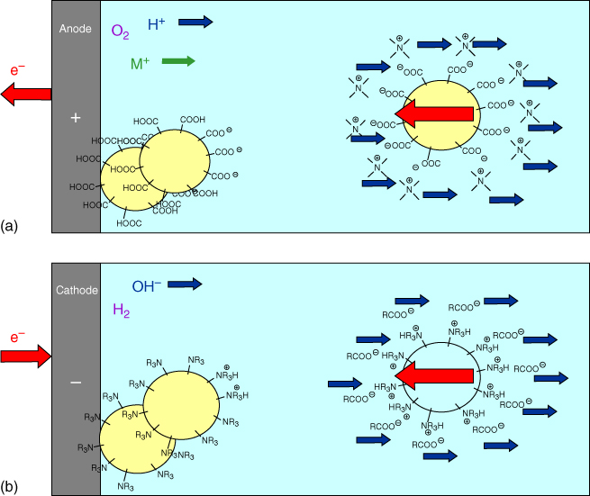
Figure 6.11 Electrodeposition. (a) Anionic deposition in which negatively charged particles are decharged at the anode, thereby releasing oxygen and dissolving metal; (b) Cationic deposition in which positively charged particles are decharged at the cathode, thereby releasing hydrogen and hydroxyl ions.
In this case cationically stabilized particles will lose their charge (upon protonation) and deposit. The advantages of this way of depositing are obviously that no oxygen is present at the surface (limiting corrosion possibilities) and no metal dissolution takes place. The process is illustrated in Figure 6.11b.
The ED coating process has several advantages. It is capable of covering complex 3D metal substrates with a perfect coverage everywhere, also on recessed areas. Moreover, it yields a uniform layer thickness that can be well controlled by adapting the current I(t) as a function of time t. The intimate interface interactions and associated passivation process lead to an excellent corrosion protection. A clear disadvantage is that the layer thickness is limited (as the deposited coating acts as an insulator) and that the process is time consuming, typically 10–30 min for the primer layer. Moreover, the coating surface follows exactly the metal surface imperfections, leading to the so‐called telegraphing effect3 (Figure 6.12).

Figure 6.12 The telegraphing effect in which surface unevenness is perfectly followed by the coating.
6.4.2 The Automotive Coating Buildup
After phosphatizing the steel, the first coating treatment is ED of the primer with as function promoting the adhesion of the subsequent layer to the steel as well as corrosion protection. As indicated, cathodic deposition is preferred, and after this deposition the coating receives it first heat treatment (bake 1). As coating materials mixed dispersions of aminated epoxy (NR3) and epoxy (NR3) are used or, alternatively, OH–acrylic dispersions (NR3) codispersed with a blocked isocyanate.
As second layer, a so‐called primer surfacer is applied, and after this layer is deposited, the coating receives its second heat treatment (bake 2). Apart from leveling off the surface imperfections of the steel, “telegraphed” by the electrodeposited primer, this layer also should provide good mechanical behavior and act as a primer for the next layer (the base coat), so that sufficient intercoat adhesion is realized. Hence, often polyesters are used as they are generally tough and impact resistant. The conventional process uses solventborne systems, typically containing polyester and amino resins, or a polyester and isocyanate. More recently and increasingly used are powder coatings, based on polyesters and epoxies, leading to hybrid systems.
As third layer the base coat is applied. This leads to a further heat treatment (bake 3), which sometimes is done together with the heat treatment for the next and last layer, the topcoat. Conventionally one uses for the base coat a solventborne system, based either on an acrylic–OH and an amino resin or on an acrylic–OH and isocyanate. The reason for using acrylics is their excellent outdoor durability. More recently, also waterborne dispersions, based on acrylics and amino resins or all‐acrylic dispersions are used. This layer provides color to the coating, and therefore pigments are added. Nowadays, often also aluminum flakes are added to reach the “flop” or metallic effect. Evidently, this layer should be light stable.
The fourth and top layer is the clear coat, leading possibly to another heat treatment (bake 3 or 4, depending on whether base coat and clear coat are crosslinked in one step or not). Conventionally a solventborne dispersion is used with normally the same system as used for the base coat. Newer developments are waterborne clear coats, based on the same system as the base coat, and powder coating, typically based on acrylic–epoxy resins and a crystalline diacid crosslinker (flow). Its functions are to provide gloss to the coating meanwhile having transparency and to protect the base coat from weathering and/or showing mar (i.e. shallow and narrow surface damage occurring due to microscale scratches or abrasion within a few micrometers of the surfaces of the topcoats [18]).
6.5 Network Formation Assessment
After application, coatings have to be crosslinked to become a film adhering to the substrate. Monitoring of the degree of crosslinking in the laboratory is normally done by following the change of one or more characteristic lines in the IR spectrum.4 More advanced techniques use IR spectroscopy in combination with ultrasound [20, 21], as, for example, applied to interpenetrating networks [22]. Alternatively, NMR can be used (see, e.g. [23]).
The solvent resistance rub test (ASTM D4752) is rather traditional, but very practical test method is used to determine the degree of network formation of a cured film by the coating's resistance to wear while swollen by a specified solvent. The choice of solvent is crucial to the relevance of this test, since it primarily probes the swellability of the crosslinked polymer binder of the paint film, limited by the degree of crosslinking: the higher the degree of crosslinking, the lower the swellability and, hence, the less wear results from the rubbing motion with a cloth. If the specified solvent is a nonsolvent for the polymer binder, the film will not swell and will likely not be affected by the solvent rubbing, even though the film is not crosslinked. The solvent rub test is usually performed using acetone or methyl ethyl ketone (MEK) as the solvent and involves rubbing the surface of the coating with a cloth soaked with solvent until failure or breakthrough of the film occurs. The type of cloth, the stroke distance, the stroke rate, and approximate applied pressure of the rub are specified. The rubs are counted as a double rub (one rub forward and one rub backward constitutes a double rub), where usually 100 or 200 rubs is the maximum. The degree of damage is also noted with a number between brackets (0–5, usually 0 denotes no visible damage), so 100 ADR means the film withstands 100 acetone double rubs (no breakthrough) but with considerable damage. The test is used widely in the paint industry because it provides a quick relative estimation of degree of cure without having to wait for long‐term exposure results.
References
- 1 Wicks, Jones, Pappas and Wicks (2007).
- 2 Wengeler, L., Schmitt, M., Peters, K. et al. (2013). Chem. Eng. Process. Process Intensif.68: 38.
- 3 Chou, Y.T., Ko, Y.T. and Yan, M.F. (1987). J. Am. Ceram. Soc.70: C280.
- 4 Tok, A.I.Y., Boey, F.Y.C. and Khor, M.K.A. (1999). J. Mater. Eng. Perform.8: 469.
- 5 Ring, T.A. (1989). Adv. Ceram.26: 569.
- 6 Huang, X.Y., Liu, C.Y. and Gong, H.Q. (1997). Mater. Manuf. Process.12: 541.
- 7 Hösel, M. (2014). Large‐scale roll‐to‐roll fabrication of organic solar cells for energy production, PhD thesis, Technical University of Denmark.
- 8 Bornside, D.E., Macosko, C.W. and Scriven, L.E. (1987). J. Imag. Technol.13: 122.
- 9 Meyerhofer, D. (1978). J. Appl. Phys.49: 3993.
- 10 Bornside, D.E., Macosko, C.W. and Scriven, L.E. (1991). J. Electrochem. Soc.138: 317.
- 11 Cregan, V. and O'Brien, S.B.G. (2007). J. Colloid Interface Sci.314: 324.
- 12 Cregan, V. and O'Brien, S.B.G. (2013). Appl. Math. Comput.223: 76.
- 13 Hayes, M.A. and O'Brien, S.B.G. (2004). Int. J. Math. Math. Sci.43: 2279.
- 14 Brinker, C.J. (2013). Dip Coating, Chapter 10. In: Chemical Solution Deposition of Functional Oxide Thin Films (ed. T. Schneller, R. Waser, M. Kosec and D. Payne), 233. Vienna: Springer.
- 15 Grosso, D. (2011). J. Mater. Chem.21: 17033.
- 16 Yimsiri, P. and Mackley, M.R. (2006). Chem. Eng. Sci.61: 3496.
- 17 Senatore, D., ten Cate, A.T., Laven, J. et al. (2013). Polymer54: 75.
- 18 For a review, see Seubert, C., Nietering, K., Nichols, M. et al. (2012). Coatings2: 221.
- 19 Makki, H., Adema, K.N.S., Peters, E.A.J.F. et al. (2016). Polym. Degrad. Stab.121: 280.
- 20 Alig, I., Lellinger, D., Agarwal, S. and Oehler, H. (2013). React. Funct. Polym.73: 316.
- 21 Alig, I., Oehler, H., Lellinger, D. and Tadjbach, S. (2007). Prog. Org. Coat.58: 200.
- 22 de Brito, M., Allonas, X., Croutxé‐Barghorn, C. et al. (2012). Prog. Org. Coat.73: 186.
- 23 Kovermann, M., Saalwächter, K. and Chassé, W. (2012). J. Phys. Chem. B116: 7566.
Further Reading
- Goldschmidt, A. and Streitberger, H.‐J. (2007). BASF Handbook: Basics of Coating Technology, 2nd revised ed. Hannover: Vincentz.
- Lambourne, R. and Strivens, T.A. (1999). Paint and Surface Coatings: Theory and Practice, 2e. Cambridge: Woodhead Publishing Limited.
- Misev, T. (1992). Powder Coatings, Chemistry and Technology. New York: Wiley.
- Patton, T.C. (1979). Paint Flow and Pigment Dispersion: A Rheological Approach to Coating and Ink Technology, 2e. New York: Wiley Interscience.
- Stoye, D. and Freitag, W. (1998). Paints, Coatings and Solvents. Weinheim: Wiley‐VCH.
- Wicks, Z.W. Jr. Jones, F.N., Pappas, S.P. and Wicks, D.A. (2007). Organic Coatings: Science and Technology, 3e. Hoboken, NJ: Wiley Interscience.