14
Self‐replenishing and Self‐healing Coatings
This chapter deals with aspects of self‐healing and surface self‐replenishing of polymer coatings. After discussing the scope and limitations of these concepts, an overview of present approaches and technologies is given. Extrinsic and intrinsic mechanisms are discussed as well as differences between reversible and irreversible networks. The example of currently applied industrial scratch‐healing automotive coatings is elaborated. An overview of self‐replenishing low surface energy coatings based on a dual experimental–simulation approach is given as well as an overview for other surface effects. Possible future scenarios are discussed.
14.1 Self‐healing and Self‐replenishing self-replenishing!functionalities"?>: Scope and Limitations
As elaborated somewhat in Chapter 1, nowadays coatings are used not only for protection and decoration but also for their ability to add still another function to the coated material. Functionalities include hydrophobicity, hydrophilicity, electrical conductivity, etc., but also self‐cleaning, low‐adherence, antifouling (AF), antimicrobial, and anticorrosive properties have been extensively investigated over the past decades [1, 2]. A long lifetime is generally required, and, hence, attention to the potential of self‐healing and self‐replenishing effects in coating material layers is more than justified. While self‐healing (with an emphasis on mechanical integrity) is a feature of the coating as a whole, self‐replenishing focuses on the reestablishment of its surface constitution. This chapter deals with both phenomena and considerations for polymer coatings.1
Most coatings have to provide a delicate mix of functional properties, and this is an essential point when one considers the design of a self‐healing effect for one of those properties: the envisaged effect and the measures to provide for it should not compromise any of the other essential functional properties of the polymer coating. Although once stated, this remark may seem obvious, design does not always adhere to this rule. In fact, this rule applies to almost all materials to be applied technologically.
Let us elaborate a bit further on this last remark: whereas the scope of self‐healing is as wide as the reach of any property of a polymer coating, the total required set of properties determines the limitations of self‐healing. Let us, for example, consider a coating that has the ability to reflow after serious scratches or cracks. Ideally we would want to design the coating in such a way that it simply reflows into the damaged area, spontaneously and within a couple of minutes. We all know the archetype of such a coating: a wet paint layer. We also know the disadvantage of spontaneous flow: on vertical surfaces the layer tends to drip down. When touched, it feels extremely sticky and can be damaged easily. In other words, this coating cannot simultaneously have the property of withstanding flow in order to feel hard and the property of easy flow in order to repair scratches. This brings us to the first type of limitations: contradictions. But there is more to this example than just the contradiction between viscous (re)flow and resistance to flow. How should the coating distinguish between a damaged area, into which material transport is desired, and a neighboring uncoated area, into which material transport is not desired? The coating, no matter how smart it may be, cannot make that decision: desired versus undesired material transport is a contradiction by itself. It is up to us, while designing the self‐healing coating, to keep those decisions for ourselves and use specific intrinsic driving forces and natural barriers to let the coating behave to our desire.
This contradiction can be resolved, however, when we use an external trigger to temporarily change the properties of a coating, to allow self‐healing, and to let the coating return to its ground state after a specific time interval. It goes without saying that during that time interval the coating should not be exposed to the influences it normally is supposed to withstand; the contradiction remains active during that stage. Examples of triggered damage recovery will be given in Sections 14.3 and 14.4.
A second type of limitations is based on the intrinsic features of the organic polymers used. Foremost, organic polymers are sensitive to weathering and aging: under the influence of moisture, UV radiation, and oxygen from the air, progressing degrading processes such as photolysis, photooxidation, and hydrolysis are inevitable. Although the thought of designing a coating that continuously or repetitively self‐heals such damages is very tempting, an ideal everlasting coating is simply not possible on the basis of organic polymers. It is a more appropriate mind‐set to think of self‐healing mitigation strategies to slow down these degrading processes. Similar intrinsic limitations of polymer coatings are damages caused by thermooxidative degradation (which shares many similarities with burning) and reactions with aggressive chemicals.
14.2 Damage Recovery on Different Length Scales: Preemptive Healing
Before we discuss the various healing strategies for polymer coatings, let us first consider the meaning of damage and damage recovery.
Functional coatings are generally active at the different interfaces involved, that is, polymer–air, polymer–liquid, polymer–substrate, and eventually polymer–polymer in multilayer systems [5]. Hence, coatings provide a superficial function, permanently in contact with the environment and users and are therefore subjected to, for example, wear, rain, dust, oils, chemicals, or bacteria, which gradually decrease their performance, leading to a shorter lifetime. This context is what functional coatings have in common with the boundary structures of living organisms such as skin, plants cuticles, mussel's shells, or cellular membranes. However, present polymeric coatings are still far from mimicking biological surfaces, which are rough and flexible, chemically heterogeneous, selectively permeable, and stimuli reactive. Moreover these biological surfaces have an extremely important characteristic on which the survival of the species strongly depends: the ability to self‐recover functionalities and maintain the boundary characteristics, that is, they show self‐healing.
As damage on coatings remains unavoidable, introducing self‐repairing mechanisms into coatings is one way to ensure a high level of performance and an extended service lifetime, with reduced energy and cost efforts associated with maintenance and repair [6]. This is particularly important for coating applications on high added value products, for example, solar cells, and electronic devices but also other applications where regular maintenance and repair is expensive or not easy to perform, such as aircrafts, marine vessels, sky scrapers, or greenhouses. Hence, polymeric coatings responding to damage inflicted by the environment or users have been and are being intensively investigated. A significant amount of literature is available [7–10], including a few book chapters [2–4, 11].
Ideally, materials are designed to perform at a desired level during a certain expected service time through which this performance should be kept at a constant level. Due to the aforementioned degrading factors, the performance of the material will be inevitably lowered, either abruptly or gradually with time, finally reaching unacceptable performance levels, that is, the material fails (Figure 14.1,2 original material [12]). Traditionally, extending the lifetime of materials is based on improving their resistance to damage (Figure 14.1, traditionally improved material). If successful, the material may have an improved performance so that it can be used for a longer time, but, if not maintained or repaired, its performance will irreversibly decrease and soon reach the critical limit of reliability. The self‐healing concept, based on recognizing and preemptive repair of damage, ideally implies that a material will be able to react and, partially or totally, recover the lost performance before it reaches the critical level of performance (Figure 14.1, ideal SH material). Ideally, the self‐healing material should be able to self‐repair back to its original properties multiple times, before a critical value of performance is reached (Figure 14.1, real SH material). The self‐healing concept thus aims at extending the service lifetime of materials, structures, and devices, not by increasing their initial performance but by implementing the concept of autonomous or induced self‐repair.

Figure 14.1 Performance of a material along its service lifetime, showing the performance of the original material, the traditionally improved material, and the ideal and the real self‐healing material.
Meanwhile the topic has ripened [6, 9], and researchers realize that for the implementation of a successful healing process, a number of requirements should be fulfilled:
- Detection and activation mechanisms. Incorporation of mechanisms to recognize a local damage and trigger the healing process.
- Healing agents. Add extrinsic or intrinsically designed components that perform the healing process.
- Transport of the healing agents to the damage loci. Implement a driving force and mobility within the material or of a phase or component of it.
- Local reconstruction or repair. Incorporate a healing mechanism that may be autonomous or require an additional energy trigger, for example, UV, local temperature, high kinetic energy, or resting time.
Damage − immediate or imminent loss of function − can occur at different length scales. A superficial scratch that distorts the surface and, hence, affects the reflection of the light degrades the decorative function. A crack that penetrates right through the coating from the surface to the interface with the substrate disables the protective function of that coating by allowing direct access of environmental influences to the substrate. These are examples of immediate damage on or close to the level and scale of the film thickness itself, which we shall denote as macro(scopic). It is important to realize that there is micro(scopic) damage indispensably associated with the macroscopic damage: the crack through the coating layer could not arise if not the coating constituents, that is, the macromolecular network segments or possibly even filler particles, have been broken (Figure 14.2a). It is also possible to discern a meso(scopic) equivalent process in crack formation: the local deformation behavior of the polymeric network segments, comprising yielding and crazing that lead to the initiation and propagation of the crack. Initially proposed in [3], others have adopted this scheme [10], although with different labeling (meso → micro; micro → nano).

Figure 14.2 Damage from the microscopic to the macroscopic level. (a) Escalation and associated phenomena and (b) recovery and associated mechanisms.
An imminent loss of function must also be considered as damage. The crack discussed above would not have formed if there had not been any buildup of stress in the coating. Besides the obvious stresses directly related to immediate damage, there can be several other kinds of stress that influence the eventual crack formation. They are built up prior to the moment of macro failure. Firstly, there can be internal stresses in the polymer coating as a result of the chemistry of network formation, mostly a combination of diminished reaction volume and loss of hydrodynamic volume: shrinking. Secondly, there can be internal stresses in the polymer coating, as well as interfacial stresses at the substrate interface, as a result of the difference in thermal expansion coefficients between polymer coating and substrate, in combination with the thermal history of the coated material. Thirdly, previous external stresses may have left their traces on the micro‐ and mesolevel, whereas they have not been revealed on the macroscale yet. Such prior external stresses can be of the same kind as the final stress that leads to the macro failure, for example, repetitive mechanical strains, eventually leading to cracking, but also of a different kind. For the latter we distinguish between reversible and irreversible effects.
An example of a reversible effect is hygroscopic strain due to the changing relative humidity of the environment. As an example of an irreversible effect, we recall that weathering exposure of a coating enhances the probability of cracking when mechanical strain is imposed. This is clue to progressive embrittlement of the coating, leading to easier crack propagation.
In damage recovery, we have to consider the same micro–meso–macro hierarchy. Damage recovery always involves material transport in the organic polymer coating, either the individual motion of small molecules or the collective motion in viscoelastic flow of the polymer binder (Figure 14.2b). The material transport needed for recovery purposes can take place within the bulk of the coatings or from the bulk to each of the three interfaces (substrate, air, filler). As stated before, material transport is rather limited in organic polymer networks. It is therefore imperative to try to limit the need for material transport in the self‐healing process as much as possible.
Appropriate timing is therefore of the essence. If one waits for damage to reach the macroscale (e.g. the crack discussed above), it is obvious that the amount of material transport to fill the crack again is likely to be too much to ask from the network of a polymer binder. If we could stop the crack from growing through crazing on the mesoscale, or even prevent the initiation of the crack on the microscale, progressively less material transport would be needed to keep the coating in the pristine state on the macroscale, that is, in relation to its macrofunction.
This, then, is the principle of preemptive healing. If we see damage as a process that starts on the microscale and escalates via the mesoscale ultimately to a loss of function on the macroscale, we can see an obvious strategy for self‐healing in preventing the damage process from escalating to the next higher level. Although the term preemptive could be interpreted such that a healing action starts before there is any damage, it actually implies that the healing action starts before the damage process reaches the level in which the function of the coating is affected. In other words, the imminent damage is averted by an invisible action, at least on the level of the macroscopic observer.
The complexity involved renders self‐healing a rather challenging matter and calls for various approaches. If the healing action should tackle the macroscale, an extrinsic approach may be more suitable (Figure 14.2b). Possibly, localized, large proportion (volume) damage, affecting bulk and interfaces, can be more efficiently repaired or prevented from further propagation. As an example, Figure 9.55b shows an electron microscope photograph of a ruptured coating on a steel panel after a falling‐bullet reverse impact test. It is clearly visible after the film ruptured in both radial and normal direction. The elastic energy present in the film as a result of internal and external stresses, once released by the rupture, not only caused widening of the cracks but also delamination from the steel substrate. Such catastrophic damage is likely beyond repair, let alone, self‐healing. Preemptive relaxation of the stress could have prevented this damage. To mitigate damage starting at the micro‐ or mesoscales, randomly distributed along a smaller volume of the material, an intrinsic healing approach is probably preferred. Broken molecular bonds and ruptured networks can be steadily repaired avoiding incremental damage (Figure 14.2b). Nevertheless, the different scales are often intertwined and a proper choice of strategy is not always straightforward.
14.3 Approaches to Self‐healing Coatings
There are several approaches to self‐healing of polymer coatings based on the healing of the binder: autonomous versus nonautonomous (triggered) [13], reversible versus irreversible [14], and extrinsic versus intrinsic healing [10]. An extrinsic approach involves the addition of external components to the system or formulation, which are not a part of the main polymer network (e.g. filled capsules [15–18] or microvascular networks [19, 20]). The main advantage is an almost instantaneous localized response to damage without any external trigger, other than the damaging event itself, for example, a scratch, or the immediate result of the damaging event, such as ions being released from a metal surface upon exposure to the corrosive environment. Figure 14.3 shows a scheme of the most successful concepts used in extrinsic self‐healing polymeric coatings. An intrinsic approach uses healing agents inherent to the material that are typically a part of the network [25–28]. While the external healing approach lacks repeatability of healing, the internal healing approach requires sufficient mobility of the network or an external trigger. Compatibility of the healing agents and minimal interference with other properties are common requirements for both approaches. The borders between the different classifications may overlap in a number of new systems. Actual mechanisms comprise:
- The use of encapsulated liquid binders and particles.
- Deformation and recovery in networks, including molecular interdiffusion and chain segregation.
- Stress relaxation in reversible networks.
- Reversible covalent networks.
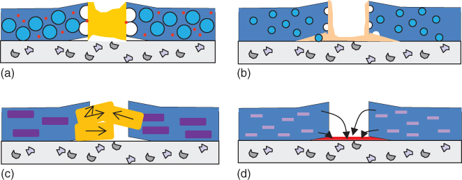
Figure 14.3 Extrinsic healing approaches in polymeric coatings: (a) 2K capsules with a liquid healing agent [21], (b) 1K capsules with a surface active agent [22], (c) expansive phases [23], and (d) release of corrosion inhibitors from inorganic carriers [24].
We discuss each of these approaches in the following paragraphs.
14.3.1 Encapsulated Liquid Binders and Particles
So, we start with encapsulated liquid binders [15–18]. The ingenious (autonomous) healing strategy adopted by White et al. [29], using microcapsules containing a healing agent for polymer composites, provides the prototype of extrinsic self‐healing mechanisms. A living polymerization (ring‐opening metathesis polymerization (ROMP)) catalyst and urea‐formaldehyde‐microencapsulated dicyclopentadiene (DCPD) monomer are embedded in an epoxy composite. Once mechanically induced microcracks rupture the capsules, DCPD monomer is released, fills the crack, and polymerizes upon the contact with the catalyst. Cracks healed with a reported 75% recovery of the original strength of the composite.
A similar encapsulation approach has been used in self‐healing coatings [30]. Microcapsules containing liquid film formers are incorporated in self‐healing coatings; the microcapsules used are typically of about 60–150 μm in diameter, and the shell is made of urea‐formaldehyde or gelatin. After the coating has been cured, any physical damage of the coating results in microcapsules bursting to release liquid that fills and seals the compromised volume. This particular coating was developed for the purpose of suppressing lead dusts.
One potential limitation for the microencapsulation approach is that the coating lacks the capability of multiple self‐healing. Moreover, long‐term stability of the catalyst remains an issue of concern. The size of the microcapsules (50 μm and above) will only allow possible applications in relatively thick coatings able to accommodate the microcapsules. In addition, the voids (in the order of micrometers), left behind because of the diffusion of reactive binder, become new loci of stress concentration.
To alleviate the once only effect, Toohey et al. [19, 31] and others [20] reported that they obtained continuous self‐healing polymer coatings by using a replenishable supply of healing materials in a microvascular network. The reaction system used is based on ROMP of DCPD. Instead of being stored in microcapsules, DCPD is kept in interconnected microchannels. Similar to the microcapsule‐based system, propagating cracks can rupture the microchannels, allowing DCPD to flow into the crack plane and to react with the ROMP catalyst embedded in the coatings. In the event of the crack reopening, more healing agent can flow through the microchannel and heal the damage again. However, the fabrication of the microvascular network appears to be challenging before widespread applications are envisaged.
Four routes have been reported so far using the idea of encapsulating liquid healing agents: (i) spherical [29] or elongated [32] polymeric capsules containing a liquid healing agent, (ii) single elongated hollow fibers filled with the healing agent [33–35], (iii) compartmented fibers [36] where the healing agent is contained in high aspect ratio compartments distributed along the fiber, and (iv) vascular networks [19]. Of these, fibers find their natural and most feasible application area in composites, while isolated capsules and nanocontainers may be more suited for self‐healing polymeric coating applications.
The basic idea behind these concepts is that upon container fracture the contained healing agent will be released to further react with other components, present in the surrounding media (e.g. H2O, O2) in a dispersed state, or embedded as other extrinsic phases in the bulk (e.g. crosslinker, catalyst). The chemistries that can be employed in this concept are numerous and depend on the application (healing function they intend to heal, environment of use, etc.) as well as on the encapsulation method. Independent of the geometry of the container, the healing process consists of three steps with three distinct time constants: (i) damage of carrier with t < seconds, (ii) release of healing agent with seconds < t < minutes, and (iii) reaction of healing agent with minutes < t < days.
Since the establishment of this route to implement healing, research has focused on several technological and scientific improvements: (i) improvement on encapsulation techniques (i.e. higher efficiency, stronger shell walls, capsule homogeneity, capsule stability, capsule geometries – from spherical to ellipsoidal, capsule size, etc. [37, 38]), (ii) selection of healing agent crosslinker/catalyst pairs suitable for different matrices and encapsulating shell materials (i.e. use of efficient less expensive catalysts, use of healing agents adapted to the media of use, and use of new encapsulated chemistries), (iii) development of healing agents not requiring crosslinker or catalyst (i.e. solvents [38, 39], water and surface reactive agents such as silyl esters [40] and oils [41, 42]), and (iv) implementation of the encapsulation concept to more application oriented research. In polymeric coatings, the main application of this concept has focused on barrier restoration and corrosion protection, as will be discussed in Section 14.5.1, while almost no studies exist on the use of this concept to restore or heal other coating functions such as color or hydrophobicity [10].
A different approach to the encapsulation of liquids is the use of solid or porous inorganic micro‐ and nanoparticles. The most common examples are (i) the expansive phases such as hydraulic inorganic grains of calcium silicate and calcium aluminate [43] or expansive clay layers [44, 45] and (ii) the use of inorganic nanocarriers such as montmorillonite [46], hydrotalcites [47, 48], halloysite nanotubes [49], and zeolites [50, 51] containing active agents such as corrosion inhibitors. In expansive phases the main healing principle relies on the reaction of the embedded particle with the environment (e.g. H2O), leading to an expansion able to close damages. In the nanocarriers approach the healing mechanism is initiated with the release of molecules or ions from the carrier, followed by the reaction of these with the surface of the surrounding substrate and/or coating. Opposite to the liquid‐container approach, no gaps are created here, when the healing agent is released or has reacted. On the other hand the scale of the damage that can be restored is significantly different; while with liquid encapsulation damage on the meso‐ and macroscale is in principle repairable, with solid nanocontainers the type of damage that can be healed remains at the micro and mesoscale (Figure 14.2).
14.3.2 Deformation and Recovery in Networks
Turning now to deformation and recovery in networks, we recall that polymer coatings generally show viscoelastic–plastic behavior. This implies that any deformation is composed of a viscous response, plastic flow, and elastic deformation [52]. The elastic, time‐independent component of the response is related to stored energy, which can be used to recover from the deformation, at least partly. The plastic, time‐independent component may contribute to healing due to residual internal stress, while the viscous, time‐dependent component in principle can also contribute to self‐healing via its memory effect. While in thermoplastic materials viscoelastic behavior is dominant, in thermosets, as used in coatings, both plasticity and viscoelasticity play a role. A more complete overview of deformation phenomena in general can be found in [53].
Let us consider a thermoplastic, that is, noncrosslinked polymer coating being subject to a surface deformation, in particular a scratch, as depicted in Figure 14.4a. The damage, a mesoscopic ditch visible as the scratch, is actually the result of material transport. Under the mechanical stress of the moving indenter, some polymer flows from the indentation area, leaving the ditch to the sides, where it is piled up. The energy put into the system to create the scratch is lost in the process of viscous flow unless residual stress due to viscoelastic (or plastic) deformation is present. After this damage, ideal recovery would imply reflow of the material from the sides into the ditch, completely leveling to the original state.

Figure 14.4 Scratch formation and recovery in thermoplastic (a) and thermoset (b) films.
This is possible, but the main driving force for this desired material transport, surface tension, which will try to keep the surface area as small as possible, is quite small. Resistance against damage recovery, however, is the same as the resistance against the damaging process itself: the viscoelasticity of the thermoplastic polymer. This means that, if we want to design a coating that easily recovers from scratching by the action of the surface tension, that is, a polymer composition with a low glass transition temperature Tg, this coating will also easily scratch to begin with. Vice versa, a coating that has a high Tg will have a high resistance toward scratching but will also show slow damage recovery.
In the unfortunate event, however, the material transport during damaging is not a gradual flow process but accompanied by microcracks in the bottom of the ditch, also those cracks will eventually have to have the ability to reflow. This is governed by the same resistance as described for the scratch.
In Figure 14.4b, the response of an ideal thermoset polymer coating is depicted. Also in this case, the scratch is formed as a result from material transport from the indented area to the sides. In this case, however, the resistance is stronger and proportional to the extent of the deformation: the elastic and/or plastic response. As a matter of fact, all or part of the energy put into the system to create the scratch, dependent on whether the yield strength is exceeded or not, is stored in the polymer network segments in the vicinity of the scratch. As soon as the external mechanical stress is taken away, the stored elastic energy is relieved, and like a spring bouncing back after being compressed, the scratch bounces back into a flat level surface. The time scale on which this happens is related to the mobility of the polymer network chains, that is, the Tg, as in the case of the thermoplastic coating, but the recovery will in principle be complete (provided that the yield strength is not exceeded) even if the surface tension forces are neglected.
This seemingly ideal behavior, however, can be drastically spoiled if at some point the mechanical stress results not only in elastic deformation but also in crack formation. During these fractures, the stored elastic energy is released untimely, and this energy is no longer useful for a directed bounce‐back movement. Material on either side of the fracture will try to bounce back by itself, no longer behaving like a unity, and some of the cracks will be left. Unlike in the case of a thermoplastic polymer coating, these fractures cannot reflow by a viscous process anymore, driven by surface tension, because now the elastic forces are opposing the desired material flow. It consequently follows that a scratch in a conventional elastic thermoset, which is accompanied by fracture, is a permanent damage.
In practice, the behavior of a polymer coating will be a superposition of the viscoelastic response (Figure 14.4a) and the pure elastic/cracking response (Figure 14.4b). The search for the optimal mix of these responses can lead to a coating with self‐healing properties to some extent, especially when use can be made of a thermal trigger for healing. In the ideal case the coating has a sufficiently high Tg, at least higher than the temperature of its exposure to the scratching, in order to minimize the indentation‐driven material transport during the damaging process. A relatively high proportion of the response is elastic, so that most minor scratches, those without crack formation, will disappear immediately and entirely. In case fracture does occur in the damage process, plastic residual strain allows for some reflow of the cracks, but healing should be mainly driven by surface tension. A temperature trigger, that is, a short heating cycle to bring the polymer above its Tg, will enhance mobility and allow the surface tension to drive the healing of the surface as much as possible.
It must be clear though that such scratch self‐healing is restricted to quite shallow scratches in the micrometer range, visible and annoying to the eye nevertheless, but insignificant in relation to the coating layer thickness. The mechanism is, therefore, mainly acting to restore the aesthetical (decorative) function of the coating. An example of this strategy is given in Section 14.4, the industrial use of scratch healing in automotive clear coats.
A related self‐healing intrinsic mechanism relies on molecular chain diffusion and/or chain segregation to create or reestablish physical linkages. This mechanism is based on the molecular mobility of polymer chains and their ability to heal the material by establishing chain entanglements across polymer–polymer interfaces formed when the two broken parts come together. Here concentration gradients or surface tension differences leading to chain diffusion are the driving forces for the healing process. These mechanisms have a strong potential for self‐repairing of polymeric coatings damaged at scales from micro to macro (Figure 14.2a) and are particularly interesting for functional coatings in which the functionality relies on presence of specific chemical groups at surfaces or interfaces, as will be discussed later in Section 14.5.
The diffusion of polymer chains in concentrated solutions and melts is described by the well‐known reptation model of chain dynamics, as discussed by de Gennes [54]. Wool and coworkers [55–57] applied such reptation model to explain thermal‐induced crack healing at polymer–polymer interfaces. According to this model, the healing of a crack is achieved once the polymer chains near the interface completely disentangle from their tubes and continuously rearrange until a new equilibrium is reached, thereby eliminating the polymer–polymer interfaces. The overall healing process evolves in five stages: (i) surface rearrangement, (ii) surface approach, (iii) wetting of surfaces, (iv) low level of diffusion across interfaces, and (v) high level of diffusion, equilibration, and randomization (Figure 14.5).

Figure 14.5 Schemes of (a) molecular interdiffusion and (b) chain end segregation models showing the stages of healing occurring at polymer–polymer interfaces: (1) surface rearrangement, (2) surface approach, (3) wetting of surfaces, (4) low level of diffusion across interfaces, and (5) high level of diffusion, equilibration, and randomization.
Thermally induced healing of cracks has been studied by bringing two pieces of the same polymer into contact at a temperature above Tg, thus allowing higher mobility of the molecular chains and leading to the gradual disappearance of the interface, with an increase of the mechanical strength due to chain entanglements (Figure 14.5a). One example is the thermally induced healing of cracks in poly(methyl methacrylate) (PMMA) and PMMA–poly(methoxy ethylacrylate) (PMEA) copolymer films that occurs at about 5 °C above Tg, with a healing time slightly larger than 1 min. Solvent‐induced healing has also been investigated, and in contrast with thermal‐induced, it can be undertaken at temperatures below Tg. Typically, the solvents are introduced into the polymers to assist the wetting and diffusion during the healing process and removed thereafter. Methanol and/or ethanol have been used to assist the healing of cracks in PMMA films [58–62], while carbon tetrachloride was used for polycarbonate (PC) [63]. In many cases, however, the use of solvents for self‐healing purposes causes excessive plasticization and swelling of the polymeric films, limiting the final healing efficiency and leading to incomplete recovery of the mechanical strength. Note that the use of solvents can also be seen as an extrinsic healing approach.
As mentioned before, apart from the formation of cracks, damage of a coating can consist of the loss of a certain function in time, such as a change in wettability or reduced adhesion to the substrate. In these cases the mechanical properties of the coating are not deteriorated; hence, rebonding of broken bonds (at the microscale) is not required. Instead, the transport or the relocation of a healing agent into the loci where the function diminishes, in a self‐replenishing way [64], will just do the trick. The rearrangement of chain ends occurring at interfaces (Figure 14.5b) provides the ideal mechanism for such self‐healing purposes.
14.3.3 Stress Relaxation in Reversible Networks
Redirecting the attention now to stress relaxation in reversible networks, we note that several attempts are dealing with self‐healing phenomena based on polymers that are constituted, at least partially, by noncovalent bonds, for example, multiple hydrogen bonds [65] and ionomers. In contrast with covalent bonds, which are permanent or irreversibly dissociated, dissociation and association of monomers and/or polymeric segments in reversible polymers are part of a dynamic equilibrium ruled by thermodynamics.
The essence of self‐healing phenomena in these reversible polymeric materials is that damage, in the form of a broken bond, can be easily mended by reassociation, whereas broken covalent bonds cannot be reassociated anymore (except perhaps reversible covalent bonds, as will be discussed in Section 14.3.4).
For polymeric networks, one can imagine a three‐dimensional (3D) network composed of monomers (having two or three reversible bonds with the other monomers) and crosslinked through reversible bonds, as well as at least one bond formed by ordinary covalent bonding. Such a reversible network can have all the typical characteristics of a normal covalent network, even though there is a dissociation/association equilibrium. If there is a sufficiently high crosslink density, there still is always a 3D network, although a part of the crosslinks is temporarily in a dissociated state. At a different moment, another fraction of the crosslinks is in the temporary dissociated state, but the same average amount of crosslinks persists to uphold the three‐dimensionally bonded architecture.
Notwithstanding the true network architecture, there are two main differences with a fully covalent polymer network. The first one relates to the equilibrium state of the crosslinks: if the equilibrium is shifted because of external influences, this will result in a changing crosslink density, in some cases even to the loss of the 3D architecture. One example of such an external influence is the addition of a solvent. A covalent network will, as a result of penetrating solvent molecules, swell to a certain degree determined by the crosslink density, stretching the polymer segments between the crosslinks to their maximal extent, but it will not completely dissolve. In contrast, a reversible network will not have a maximum degree of swelling if the equilibrium of the reversible crosslinks is shifted to the dissociated state by the penetration of the solvent. The dissolution rate is strongly depending on the rate of solvent penetration and bond dissociation, and the network structure could eventually be lost entirely. To a coating's disadvantage, such behavior would imply a high vulnerability to chemical solvents, that is, gasoline on an automotive lacquer, or stains, like coffee or wine markings on a tabletop lacquer. To its advantage, however, such a coating could self‐heal a structural damage of broken bonds by reassociation of the crosslinks.
The second main difference relates to the time scale of the equilibrium crosslinks: a covalent crosslink is able to store elastic energy upon deformation of the network for an (in principle) indefinite time, but a reversible crosslink may dissociate at one point in time and space and later reassociate at another locus, effectively releasing energy. When the time scale of association/reassociation is larger than the time scale of the deformation stress, the reversible network will behave in the same way as a covalent network, but when it is much shorter, it will not have the structural integrity of a normal covalently crosslinked material. For example, a rubber band based on a reversible polymer network could be stretched around a rolled‐up newspaper, but unlike normal rubber bands it would gradually loosen its grip around the newspaper and widen up [66].3 It should be stressed, however, that although creep may be considered a disadvantage for structural materials (bands, tires, bars, moldings), this is not necessarily so for a coating. Coatings generally do not have a load‐bearing function; they are applied on other materials that provide the overall structural integrity. Their main function is to decorate and protect the underlying material and, increasingly, to provide another functionality. For these applications creep can also be regarded as an advantage: it allows relaxation of stresses.
As outlined in Section 14.2, relaxation of both internal stresses and externally imposed stresses is an important feature for preemptive self‐healing of coatings: it helps to prevent escalation of damage from the microscopic level to the macroscopic level, that is, film cracking.
The relation between physical aging and internal stresses in coating performance is well known for covalently crosslinked coatings, as are methods to measure such stresses [67]. The usual way to make internal stress in a coating visible and measurable is to apply the coating on a metal strip of known thickness and stiffness. A developing tensile stress, for example, while cooling the coated strip after curing at elevated temperature, will reveal itself in a concave bending of the strip (coated face inside), while a compressive stress will reveal itself in a convex bending (coated face outside). The curvature of the metal strip is proportional to the stress in the coating and can be used for quantification (see Section 9.9).
As indicated before, residual stress as a result of plasticity can be relieved either via a thermal treatment or via viscoelasticity. Viscoelastic stress relaxation of covalently crosslinked coatings is possible to a limited extent too. Close to or above the Tg, the polymer backbone segments have sufficient mobility to yield to the stress. The crosslink density determines the maximal degree of yielding relaxation, stretching the polymer segments between the crosslinks to their maximal extent, in close analogy to the solvent swelling discussed earlier. Reversible networks will not be limited by such a maximal extent of relaxation, if the time scale of dissociation/reassociation is much shorter than the time available for stress relaxation. Such a creeping network should be able to completely relax internal stresses, such as cure shrinkage and thermal stresses, but also large imposed stresses, such as convex bending of the underlying substrate material, given sufficient time for relaxation in relation to the kinetics of the dissociation/reassociation equilibrium. The influence of the polymer backbone segments will remain important; however there is sufficient molecular mobility to address the crosslinks for yielding relaxation only close to or above the glass transition temperature.
There have been attempts to photo‐induced stress relaxation in coatings [68], but there seem to be no examples known yet in literature in which reversible networks are reviewed for their ability to autonomously and preemptively heal stresses in coatings. Section 14.3.4 will elaborate on this topic [11].
The principle behind intrinsic healing mechanisms using noncovalent bonds is similar to what has been described in the previous case of reversible (covalent) bonds. High mobility can be gained by breaking bonds and allowing material reflow, and mechanical strength can be restored by reforming bonds. Also in this case, the mechanical properties of the materials may suffer from the introduction of weaker noncovalent bonds for the healing purposes.
Within this approach, five molecular interactions are being used: (i) hydrogen bonds, (ii) ionomers, (iii) π–π stacking interactions, (iv) host–guest complexes, based on noncovalent hydrophobic interaction, and (v) metal–ligand coordination bonds (Table 14.1), which are at an initial research stage but could be promising, for example, for the recovery of adhesion between coatings and metallic surfaces.
Table 14.1 Selection of intrinsic self‐healing polymer systems that have been (or have the potential to be) implemented in polymeric coatings.
| Interaction | System | Mechanism/chemistry | Conditions (T, t, etc.) | References | |
| Molecular interdiffusion and chains segregation | Dangling chains diffusion (bulk healing) | PS | — | 70–120 °C (Tg ≅ 100 °C) | [55] |
| PMMA | Locally effective lowering of Tg | T > Tg | [58–62] | ||
| PC | Locally effective lowering of Tg | T > Tg | [63] | ||
| PSPMMA | — | 30–125 °C (Tg ≅ 110 °C) | [69] | ||
| Self‐replenishing (surface healing) | PUPE/fluorinated dangling chains | Surface segregation | RT, a few minutes to hour | [64, 70, 71] | |
| Nanocomposite‐porous films/fluorinated compounds/(PEO) chains | Surface segregation | RT, a few minutes to hour | [72–75] | ||
| Reversible bonds | Thermoreversible bonds | Furan–maleimide‐based thermosets | DA | 145 °C, 25 min | [76, 77] |
| Macrocyclic derivative of DCPD | DA | DA, RT, rDA, 90–120 °C | [78] | ||
| Furan–maleimide functionalized epoxy, polyketones, PS, PE, PMMA, polyamides, and polyesters | DA | DA – RT, rDA – 90–120 °C | [79–92] | ||
| Sulfide bonds | Disulfide (S─S), tetrasulfide, (S─S─S─S), thiol (S─H) exchange | Sulfur bonds | Various Ts and UV | [27, 93, 94] | |
| Trithiocarbonate containing polymer – poly(n‐butyl acrylate) | Sulfur bonds | UV | [95, 96] | ||
| Other interactions | Chitosan in crosslinked PU network. Oxetane groups | Urea bonds cleavage | UV | [72, 73, 75] | |
| Alkoxyamine functionalized poly(methacrylic esters) | Radical recombination | RT, wetting with DMF, 24 h | [97, 98] | ||
| Cinnamoyl‐functionalized polymers | Cycloaddition | UV | [99, 100] | ||
| Noncovalent bonds | Supramolecular (H‐bonds) | Fatty acid derivatives with diethylenetriamine reacted with urea; poly(urethanes); epoxy–amine | H‐bond networks quadrupole H‐bonds | Pressure | [26, 101–104] |
| PU | H‐bond networks | Electromagnetic radiation | [105, 106] | ||
| Ionomers | Thin films/PEMAA | Ionic groups rearrangements | Various | [107–111] | |
| π–π Donor–acceptor stacking | Poly(diimide/pyrenyl) end‐capped PA or poly(siloxane) | π–π stacking networks | 50–80 °C | [112–114] | |
| Other interactions | Layers of polyelectrolytes on PDMS | H‐bond ion networks | Water or humid environment | [115] | |
| Linear polymers crosslinked with pyridine groups using metal complexes | Metal–ligand cleavage | Immersion in complexes solution, T | [116–119] |
RT, room temperature/ambient conditions; DA, Diels–Alder; rDA, reverse Diels–Alder; PS, poly(styrene); PMMA, poly(methyl methacrylate); PC, poly(carbonate); PSPMMA, poly(styrene)‐b‐poly(methyl methacrylate); PUPE, poly(urethane polyesters); PEO, poly(ethylene oxide); PU, poly(urethane); PEMAA, poly(ethylene‐co‐methacrylic acid); PA, polyamide; (PS)DCPD, dicyclopentadiene; min, minutes; h, hours.
Generally, most of these molecular interactions will require energy triggers to operate, for example, temperature or/and pressure. The typical temperatures required here are lower as compared with those for reversible covalent networks, making these mechanisms very interesting for polymeric coatings. The application of pressure will be, however, more restricted for polymeric coatings for practical reasons.
The use of hydrogen bonds is among the most successful healing routes so far, as demonstrated by Cordier and coworkers [26, 101] for supramolecular rubbery materials. After a cut damage into two pieces, the rubber could be healed by the application of a small pressure between the loose ends combined with heat to increase the healing ability. Application in polymeric coatings is probably cumbersome due to the requirement of application of a controlled pressure.
Sijbesma and coworkers [102, 103] reported a special type of supramolecular polymer networks, based on quadruple hydrogen bonding ureido‐pyrimidinone moieties (UPys), which show more promising features for self‐healing polymeric coatings. In these materials the healing mechanism acts at the nanoscale, in response to local stresses, avoiding the growth of damages into the microscale, in a preemptive mode. Recently, a similar concept of delayed elasticity and preemptive healing was proposed for epoxy–amine coatings, using single H‐bond moieties introduced in the polymer network via an amide (acetamide), which was coreacted with a diamine (jeffamine) and an epoxy resin, in different ratios of the (co)amines in relation to the epoxy [104]. The introduction of H‐bonded crosslinks allowed enough flow to fully recover a ≈70 µm deep cut on a coating, in about 10 min at 45 °C, with minor effects on the polymer mechanical properties or adhesion to the substrate. The introduction of a larger amount or multiple H‐bonds in the system could further improve the healing performance of these epoxy–amine coatings, however, probably at the cost of their good adhesion, barrier, and protective properties. Nevertheless, such self‐healing polymer materials could be very interesting, for instance, for avoiding fatigue‐related damage in polymeric coatings.
Ionomers are a second type of molecular interactions with high potential for self‐healing materials. The systems based on ionomers contain species like acid groups in the form of metal salts (ionic species) that are bonded to the polymer structure creating electrostatic interactions or aggregates. These ionic clusters can undergo transitions and relaxations at certain temperature ranges, leading to an increase of mobility of the polymers that can have a significant impact on the material's mechanical and physical properties [107]. Ionomers have been applied for ballistic healing [108, 109], and recent studies have shown their applicability as coatings as well [120].
The third noncovalent type of interactions for self‐healing materials is based on donor–acceptor π–π stacking. So far, only a few papers [112, 113] have reported the healing abilities of these systems, although with promising results. The concept proposes a mechanically robust healable polymer system based on the complexation of a chain‐folding (co)polyimide with a pyrenyl end‐capped polyamide. The polyimide chains form noncovalent bonds by multiple intercalations of π‐electron‐rich pyrenyl end groups, into the designed polyimide chain folds. These systems reached a healing efficiency of 100% in about 5 min at 50 °C and raise high expectations, although the current status is insufficient to evaluate possible limitations and strengths of these systems.
14.3.4 Reversible Covalent Networks
Finally we turn our attention self‐healing polymers by using reversible covalent bonds, which can associate/dissociate under specific conditions, and allow for rapid conformational changes that ensure a healing action in response to damage. Such behavior depends on the association/dissociation characteristics of chemical bonds, the overall mobility of the molecules, and the system environment. This intrinsic mechanism is particularly relevant for recovering damages at the meso‐ and microscales (Figure 14.2a), acting at the polymer networks and molecular bonds levels (Figure 14.2b). A wide range of reversible chemistries is available for designing intrinsic self‐healing mechanisms, such as Diels–Alder (DA) reactions [76–78] (namely, with furan–maleimide derivative functionalized epoxies, polyketones, poly(styrene), PMMA, polyamides, and polyesters [79–92]), disulfide bonds [27, 93, 94], trithiocarbonate exchange reactions [95, 96], radical recombination [97, 98], and others; see Table 14.1.
Wagener et al. [21] reported in 1991 a thermally reversible polymer on the basis of azlactone rings, as shown in Figure 14.6. But a temperature increase to above 200 °C is needed for reversible reactions. Reversible crosslinked polymers based on urea linkage were also reported [121], in which a gel–sol transition was observed in a DMF solution of two polymers, poly(4‐vinylimidazole‐co‐methyl methacrylate) and poly(3‐isopropenyl‐cx, cx‐dimethylbenzyl isocyanate‐co‐methyl methacrylate), as the temperature varies between room temperature and 110 °C (Figure 14.7). However, the reversibility of the urea linkage in bulk was not discussed. Nonetheless, the popularity of urethane in coating industry may enable this type of chemistry to be applied as self‐healing polymer coatings.
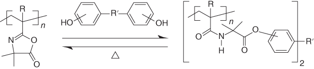
Figure 14.6 Reversible covalent networks based on azlactone and phenol.

Figure 14.7 Reversible covalent networks based on imidazole and isocyanate.
DA reactions are known to be reversible for decades. An outstanding example is a thermally remendable polymer material developed by Chen et al. [76, 77] on the basis of a thermally reversible DA reaction. The material can, when heated to 120 °C, heal multiple times and retain more than 60% of its original strength.
Some of these chemistries have been specifically investigated for polymeric coatings, namely, by the incorporation of reversible crosslinking functionalities into the polymer backbone, such as DA adducts. Wouters et al. [89] reported thermally reversible polymeric networks based on block‐(co)polymers containing furan moieties that were further crosslinked with bismaleimides, using DA reactions (Figure 14.8a,b). These systems could be implemented in acrylic‐based powder coatings. For alternative (epoxy–amine)‐based coatings formulations, the authors reacted a diamine with a bifunctional epoxy containing reversible DA adducts [89]. Another example was reported by Scheltjens et al. [80] with furan‐ and maleimide‐functionalized epoxy resins, which were reacted with diamines (e.g. jeffamine) and further crosslinked with a bismaleimide (Figure 14.8c–e). Care has to be taken though that retro‐DA reactions may be dependent on stereoisomerism for their activation temperatures, especially with aliphatic bismaleides [122].

Figure 14.8 (a) Furfuryl methacrylate‐block‐butyl methacrylate (FMA‐b‐BA) (co)polymer; (b) Schematic representation of the crosslinked network made by reacting with a bismaleimide according to DA (reversible acrylic‐based polymer networks for powder coatings); (c) Furan‐modified, (d) maleimide‐modified epoxies; (e) Jeffamine as components for reversible epoxy–amine networks containing Diels–Alder (DA) adducts.
Scott et al. [68] recently reported photo‐induced plasticity in thiol–ene‐based crosslinked polymer materials, which exhibit stress/strain relaxation without material property changes upon UV exposure. The result was achieved by introducing radicals via photocleavage of residual photoinitiator in a polymer matrix, which then diffuse via addition–fragmentation chain transfer of midchain functional groups (Figure 14.9). But applications may be limited to rubbery networks in which sufficient diffusion of segments can be assured. Similar reversible polymers on the basis of radical crossover reaction between alkoxyamine‐based polymers have been reported by Otsuka et al. [123]. The reversible reaction is triggered by temperature increase.
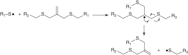
Figure 14.9 Reversible covalent networks based on thiol–ene combination.
Reversible redox reactions of sulfur bonds, which can be triggered by light or the presence of oxidants/reducers, have also been extensively investigated for self‐healing materials, specially thiol–disulfide reactions, which in the oxidized state form disulfide bonds (S–S) that can be ruptured by reduction to form thiol groups (S–H) [28, 93]. Matyjaszewski et al. [95, 96] reported photo‐induced healing of polymers based on reshuffling of trithiocarbonate bonds, while Canadell et al. [27] designed promising polymer systems based on disulfide interchange reactions (S─S to S─S), rather interesting for polymeric coatings, as they use moderate temperatures and times to heal (≅ 1 h, 60 °C). These approaches are potentially attractive for polymeric coatings especially due to the different existing chemical routes for promoting healing, the possibility to induce multiple self‐repairing events and the range of different triggers available.
Although reversible covalent polymers can in principle be used as self‐healing coatings that are capable of healing multiple times, there are some disadvantages too. First, the dynamic reactions depend on energy triggers, such as thermal treatment, light (UV) irradiation [95, 96, 99, 100, 124], pH changes [125], or the addition of catalytic additives; hence, healing is not autonomous. Second, when the external trigger is applied, the whole material, including the parts where no healing is necessary, will be affected. For bulk materials whose shape is of importance, this may pose a major drawback, unless for such dynamic systems the local reversibility (i.e. bond forming–breaking reactions) is significantly faster than the overall changing processes (e.g. polymer flow and macroscopic deformation). For polymers used as coatings, this disadvantage does not necessarily apply since the shape of a thin coating depends primarily on the substrate it covers. Moreover, local heating can be much more easily applied. Therefore, we believe that reversible covalent polymers hold promise in obtaining self‐healing polymeric coatings.
An appealing idea to solve problems related to weakening of a self‐healing polymer during the healing step is the design of intrinsic self‐healing polymeric systems with hybrid architectures containing both reversible and irreversible bonds, allowing high versatility by varying the polymer architecture [12]. DA‐based polymers were successfully used in powder coating systems [89] as well as liquid‐based polymers [126]. Although these systems show good healing behavior, the temperatures needed to reach the necessary flow (around 120–150 °C) limit their applications. Disulfide‐based systems, on the other hand, offer sufficient flow at moderate temperatures (60–70 °C). Canadell et al. [27] presented an epoxy coating with disulfide bonds capable of restoring small damages. A particularly interesting hybrid system was recently reported by AbdolahZadeh et al. [94] consisting of dual organic–inorganic crosslinked networks made by a sol–gel process, capable of restoring relatively large‐sized damage (≅500 μm) upon the application of moderate temperatures and pressures while maintaining good mechanical properties. These systems contain nonreversible (covalent) crosslinks as well as reversible tetrasulfide (S─S─S─S) groups. The hybrid sol–gel architecture exhibits an attractive combination of significant recovery of bulk damage as a result of mesoscopic flow at modest temperatures (e.g. the maximum healing kinetics was observed at 70 °C) while preserving adequate mechanical properties during the healing stage due to the presence of a stable crosslinked network (Figure 14.10).

Figure 14.10 (a) Idealized structure of a hybrid sol–gel intrinsic self‐healing polymer network. Insets show some of the key chemical structures used on the hybrid systems, (b) reversible tetrasulfide (S─S─S─S) bonds, (c) inorganic crosslinks, and (d) organic epoxy–amine crosslinks. Source: Adapted from Ref. [99].
Coatings using triggers other than temperature have also been reported such as moisture‐promoted healing copolymer proposed by Zhang et al. [127]. The initial reported results show gap closure by means of a zipping mechanism promoted by water, although the question remains whether these systems will be capable of maintaining good properties after long immersion in water.
14.4 Industrial Practice
What can be more annoying in modern life than an ugly scratch on your mobile status symbol, your new and otherwise shiny car? It is not surprising that the first examples of self‐healing coatings can be found in the automotive finishes industry. Well, the claims of the paint and car manufacturers relate to relatively small car wash scratches only (we are still vulnerable to the large scratches), and there is a considerable dose of sunshine necessary to trigger the healing process, but all is fair: scratches do disappear.
Automotive coatings usually consist of four layers, the upper two being the colored base coat and the transparent topcoat. The latter, also referred to as clear coat, protects the underlying layers from environmental influences (moisture, sunlight UV, bird droppings, scratches, etc.) and determines for a large part the optical appearance of the car, most importantly the gloss. Low‐ and middle‐priced cars generally have a topcoat of acrylic polymers crosslinked with melamine resins; higher price level cars can have topcoats of acrylic polymer crosslinked with polyurethane resins or all‐polyurethane systems. Automotive paint manufacturers have designed and optimized their clear coat formulations for the best preservation of the car's glossiness during its lifetime and use, determined by the consumer's geographical preferences and perceptions [128]. Typically, a car in the United States or Australia has a clear coat with high crosslinking density and high glass transition temperature, withstanding solar irradiation, sand blasting, and stone chipping. A European car on the other hand sees much less sunlight but sees the inside of the car wash much more frequently than its US counterpart.
European automotive topcoats, therefore, have lower Tgs and lower crosslink densities. It is a well‐known phenomenon for some 20 years, self‐healing avant la lettre, that annoying car wash bristle marks on such clear coats easily disappear or at least become less visible when the car is exposed to heat for some time. The surface of a car can easily reach 70 °C when exposed to the summer sun for an hour. The principles of this phenomenon are described in Section 14.1.
The customer's perception of the added value of a self‐healing car coating, however, has been an inspiration to some paint material suppliers and car manufacturers to elaborate further on this scratch‐healing phenomenon and use it in branding. Nissan, in cooperation with Nippon Paint, introduced the X‐Trail model in Europe in 2006, proclaiming it to be the first car with a self‐healing topcoat that makes car wash bristle marks disappear completely within weeks and with a guarantee on that property for 2 years.
Bayer Material Science, supplier of polyurethane resins for acrylic‐polyurethane and all‐polyurethane clear coats (Desmodur, Desmophen), started research in 2003 into reconciliation of the requirements for etch and weathering resistance with the ability to self‐heal small scratches. The classic difference between acrylic‐melamine clear coat performance (high crosslink density, etch and weather resistant, but brittle) and polyurethane clear coat performance (low crosslink density, weatherable, and flexible, but less etch resistant) formed the basis of their approach. In 2006, they announced a new all‐polyurethane concept that managed to combine a relatively low glass transition (flexible network bows [22]) with a considerably increased crosslink density, as the solution to this paradox. This new concept is now being used by major automotive paint suppliers [129]. Figure 14.11, adapted from a Bayer Materials Science brochure [22], illustrates that the mechanism of scratch reflow is indeed not different from earlier scratch‐healing coatings (Section 14.2) but optimized for the effect: while the high crosslink density increases the elastic response of the coating to the imposed viscoplastic deformation, the low Tg (and the low‐associated yield strength) prevents crack formation in the scratch and assists in the reflow process triggered by increased temperature.
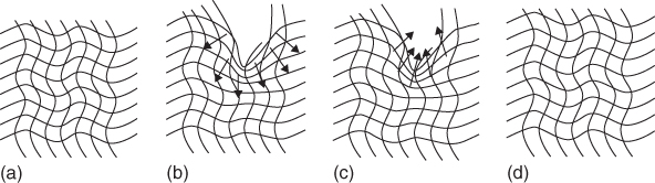
Figure 14.11 Bayer Materials Science's representation of scratch‐healing polyurethane coatings, showing (a) virgin coating; (b) inflicted damage, for example, by car washing; (c) recovery by thermal treatment above Tg (2 h, 60 °C); (d) recovered coating by reflow.
14.5 Approaches to Self‐replenishing Coatings
Apart from crack formation, damage of a coating can be also the loss of a certain other function in time, such as deterioration of the adhesion between the coating and the substrate, loss of UV protection, or loss of the anticorrosion function for metallic substrates. Many of the current functional polymeric coatings rely on their surface chemical groups for a special performance or functionalities, such as extreme water repellency, self‐cleaning behavior (via superhydrophobic or superhydrophilic mechanisms) or anti‐(bio)adhesion (i.e. low adherence of proteins and other biofoulants). Loss of these functions is also considered as damage.
In these cases, a coating does not suffer from a significant loss or reduction of mechanical strength; therefore the rebonding of broken bonds, as discussed in the previous sections, may not be necessary. Instead, an intelligent way is needed to heal the coating damage by recovering the coating function. Certain coating functions are due to the presence of a specific species, which can be a low molar mass free molecule or a dangling chain attached to a crosslinked network. For instance, low surface wettability of a coating can stem from low surface energy fluorinated or silicone‐based chains; for anticorrosion purpose, an active corrosion inhibitor can be added. In order for the coating function to recover, the specific species need to be transported, or they can move by themselves in a self‐replenishing fashion, to the loci where the coating function diminishes. The driving force of these specific species may include differences in surface energy, environmental changes (such as pH and temperature), and so on; in addition, they should enjoy a certain degree of mobility in a coating system for relatively rapid transportation.
Since surface functionalities are strongly related to the molecular characteristics of the surface, self‐repairing mechanisms acting at the micro‐ and mesoscale seem to be more suitable to repair surfaces; hence, intrinsic self‐healing approaches have been mainly investigated for this purpose. In particular, promising systems have been reported for polymeric coatings using molecular interdiffusion of chain ends or impregnated additives and self‐replenishing mechanisms.
Special wettability behavior, ranging from (super)hydrophobicity to (super)hydrophilicity, is desired for functional coatings with self‐cleaning, antifog, AF, or low‐friction properties. Accordingly, self‐healing mechanisms that aim retrieving the surface chemical composition upon surface damage, to maintain the wettability characteristics, have been intensively investigated.
We discuss subsequently in Section 14.5.1 barrier and corrosion protection and in Section 14.5.2 interfacial bonding, while Section 14.6 deals in some detail with wettability and adhesion issues in relation to self‐replenishing low surface energy coatings.
14.5.1 Barrier and Corrosion Protection
Both extrinsic and intrinsic approaches have been employed to restore barrier and corrosion protection. For corrosion protection the extrinsic route is by far the most explored one, the main reason being the relative ease of incorporation of both capsules with liquid healing agent and doped nanoparticles in existing coatings.
Two main approaches have been reported so far using liquid healing agents for corrosion protection (as schematized in Figure 14.3a,b): (i) the 2K concept using an encapsulated agent with dispersed catalyst [130] and (ii) the 1K concept using water reactive agents, such as tung oil [41], and water and surface reactive systems as silyl esters [40]. Following this last idea, recent work has successfully shown the possibility of encapsulating an oil‐corrosion inhibitor double agent (triazole derivative) for active corrosion protection [131]. The mechanism of capsule opening has also been investigated where the opening mechanism can be mechanical as in the original concept by White et al. [29], triggered by the corrosion process itself using pH changes [132] or redox variations [23, 133] or due to environmental factors such as UV irradiation [24].
Inorganic nanoparticles (Figure 14.3d) have been used mainly to restore the protective layer on top of a metallic surface without necessarily filling the gap created during the damaging effect (i.e. in case of mechanical damage). The concepts reported so far focus on the use of the corrosion processes themselves to trigger the release of the functional agents, namely, corrosion inhibitors or passivating agents. Several carriers have been reported to be efficient, although the ones that have attracted more attention are hydrotalcites [47, 48] and more recently zeolites [50, 51]. Independent of the carrier, the traditional and most extended approach consists of the introduction of one corrosion inhibitor in the carrier. The inhibitor will be released by ion exchange due to the presence of metal cations in the surrounding or anions from the corrosive environment (e.g. Cl−) [47, 48], pH changes as in particles coated with polyelectrolyte shells [48], or by desorption control from adsorbed corrosion inhibitors on nanoparticles [48]. Recently a new route using two different inhibitors doped in one single carrier has been successfully proposed [50]. The concept has been demonstrated using a NaY zeolite carrier and Ce3+ and diethyldithiocarbamate as the corrosion inhibitors for the Al alloy AA2024. This concepts propose the fast release of one inhibitor by desorption and the slowest and sustained release of the second inhibitor by ion exchange, leading thus to a beneficial fast and sustained response [50] and, hence, controlling the corrosion process for longer times.
Another example is a self‐replenishing, anticorrosion coating in which a corrosion inhibitor self‐replenishes at the coating/metal interface [134]. Others [135] used a layer‐by‐layer assembly technique to entrap a corrosion inhibitor (benzotriazole) to silica nanoparticles and then incorporated the nanoreservoirs in epoxyfunctionalized ZrO2/SiO2 sol–gel coatings deposited onto an aluminum alloy. The release of benzotriazole is initiated by pH changes during corrosion of the aluminum alloy.
Intrinsic healing concepts have also been proposed to restore barrier and hence potentially corrosion protection with the advantage that the healing event can be repeated multiple times. Most of these concepts employ temperature as the trigger, leading to the necessary mobility to alleviate damage.
The development of self‐healing coatings also requires the development of quantitative and reliable characterization techniques [136]. Since its proposition as a technique to quantify the level of corrosion protection using doped nanoparticles [47] and barrier restoration with encapsulated healing agents [47], electrochemical impedance spectroscopy (EIS) has become one of the most commonly used techniques due to its ease of application. An alternative to traditional EIS is odd random phase multisine electrochemical impedance spectroscopy (ORP‐EIS) that accelerates the measurement reducing the influence of instabilities [137]. Despite the potential of EIS, attention must be put to the correct interpretation of the results obtained with this technique and even more so when dealing with the selection of electrical equivalent circuits for more quantitative analysis [138].
Local electrochemical techniques have also been proposed to quantify the level of restoration at the damage itself (e.g. scratch, hole). The scanning vibrating electrode technique (SVET) allows in situ monitoring of the distribution of anodic and cathodic areas at the surface. This technique has been used for self‐healing coatings using corrosion inhibitors [139] where the suppression of the corrosion activity is shown as disappearance of the local activity. SVET has been proven to be very effective also in systems aiming at gap closure or surface coverage using microencapsulated liquid healing agents [40]. Although more complex in use, scanning electrochemical microscopy (SECM) has been proven a powerful technique to follow the healing process of corrosion inhibitors, encapsulated agents, and intrinsic polymers by following both the redox activity at the metallic surface (redox mode) [140] and the redox mode combined with the feedback mode (to follow topography changes) [140].
In order to obtain direct visual information about the level and type of protection offered by a self‐healing coating, Garcia et al. recently proposed the use of X‐ray tomography coupled to EIS [141]. Figure 14.12 shows how a silyl ester is capable of reducing both the under‐film delamination (white lines) and pitting (white dots) of a coated AA7050 panel immersed in a corrosive solution. A quantification of these parameters led to a major understanding of the effect of the silyl ester, otherwise not fully understood by electrochemical methods alone.
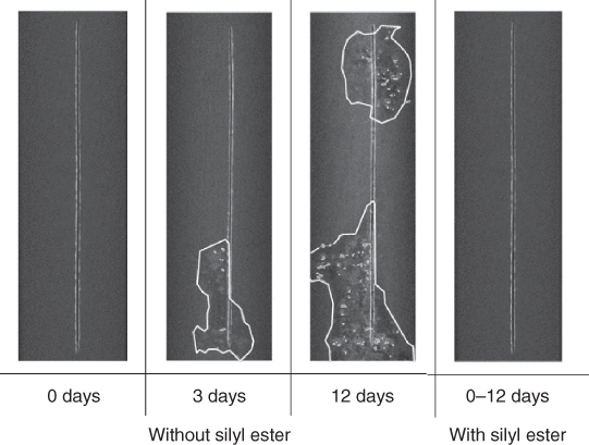
Figure 14.12 Delamination (white irregular lines) and pitting (white‐gray dots) around a scribe (vertical line) of a coated AA7050 panel exposed to 0.05 M NaCl in distilled water, showing a significant time delay in the appearance of both delamination and pitting using a silyl ester as healing agent (from 3 days to more than 12 days). Source: Adapted from Garcia et al. 2014 [141].
14.5.2 Interfacial Bonding Between Dissimilar Materials
Adhesion between similar materials (e.g. polymer A–polymer A) as well as between dissimilar materials (e.g. metal–polymer, polymer A–polymer B) is a critical aspect in many fields such as coatings technology and composite materials. Loss of adhesion is a critical factor in coating technology, leading to accelerated localized corrosion [10]. In other application fields, such as packaging and electronic devices, loss of adhesion is one of the most critical reasons for device malfunction [142]. It is clear that many application fields could significantly benefit of the implementation of self‐healing concepts aiming at interfacial bonding restoration. Despite there are several papers focusing on the restoration of polymer–fiber interfaces in composites, the restoration of interfacial bonding (i.e. adhesion) between a coating and a metal has not yet attracted as much attention as barrier/corrosion restoration in coatings.
In a recent attempt Jin et al. [143] used an encapsulated DCPD and a dispersed Grubbs catalyst in an adhesive layer. Despite the initially encouraging results, the authors could not show full adhesion recovery as the studied adhesive showed a high component of cohesive failure. In a different study Mardel et al. [144] demonstrated that the incorporation of certain corrosion inhibitors (i.e. Ce(dbp)3) improves the resistance to filiform corrosion by the formation of a somewhat adhesive oxide between the metal and the coating once exposed to humid environments. The use of nanoencapsulated or compartmented adhesion promoters that upon damage are released and wet both the coating and metal interface reacting with either materials provides an interesting route to be followed to implement interfacial healing. Interestingly, Lane et al. [145] showed a proof of concept for this approach for the repair of dielectric interfaces, although the concept was not further developed. Despite the potential of intrinsically healing polymers to restore adhesion is probably higher than that of extrinsic approaches [10], there are less examples in literature using this approach. Lafont et al. used disulfide bonds to design a temperature and pressure triggered self‐healing adhesive [142]. It is expected that in the near future more research addressing interfacial restoration will be published.
Segregation of interacting groups can also lead to better adhesion of heterointerfaces. The conventional solution for heterointerfaces is to use block copolymers. It seems possible to predict the increase in the (thermodynamic) work of adhesion for these interfaces from relatively simple molecular simulations. An example is provided by Kisin et al. [146] by the adhesion between polystyrene‐co‐acrylonitrile (SAN) and copper metal by using polystyrene‐co‐maleic anhydride (SMA)–SAN block copolymers. Experimentally this modification resulted in an increase of adherence force of 100%, as measured with the pull‐off test [146, 147]. Similar effects can be envisaged for the interface between filler particles and matrix in polymer coatings as well as between coating matrix and substrate if a release of block copolymer can be realized. A small residual amount of these block copolymers in the matrix might do the trick provided sufficient mobility is present.
14.6 Self‐replenishing Low Surface Energy Coatings
Having discussed the general aspects and principles of self‐healing in the bulk and self‐replenishing at surfaces, we now turn to wettability and adherence in relation to self‐replenishing low‐adherence coatings. The surface of a coating is very important and governs, among other properties, wettability and friction of the coating. It is well known that the surface composition of a coating may differ significantly from its bulk composition. Low‐adherence coatings are widely used today, since their water/oil repellency makes them easily cleanable (a well‐known example is PTFE). The low surface tension is provided by, for example, fluorine‐ or silicon‐containing species that are present at the film surface. Low‐adherence coatings have already been developed via surface segregation of fluorinated species [148]. However, it has been shown that the fluorine‐enriched layer is very thin, and the coating may not sustain low adherence upon mechanical abrasion.
The next three (sub‐)sections deal with an autonomous and intrinsic surface‐repairing concept,4 based on self‐replenishing of surfaces [64] through the self‐segregation of functional groups connected to the polymer network toward the damage loci and using energy differences as driving force. In this way the low‐adherence character of fluorinated polyurethane coatings [64, 70, 149] is maintained.
In order to control and optimize the self‐replenishing of such polymeric systems, it is of primordial importance to understand (i) how the systems are initially formed (crosslinked) [74], (ii) how surface segregation occurs during film formation and during damage recovery [70, 150], and (iii) which parameters can be tuned to control this self‐segregation behavior toward an optimum self‐replenishing [70]. To reach these levels of understanding, a combined experimental–simulation approach running in parallel and in a loop‐feeding process was used, which was applied to model polymeric and composite coatings (Figure 14.13). Typically a number of parameters in analogous experimental and simulation setups were varied. The experimental approach revealed important aspects of the film formation, for example, the best combination of fluorine concentration (healing agent) in the formulation and specific length of a polymeric spacer to reach optimum hydrophobicity upon film formation [150] or the minimum healing agent concentration for a maximum recovery [70]. From simulations additional insight into the dynamics and network structure of the films was obtained, such as the existence of a depletion zone beneath the top surface‐segregated layer, the existence of clusters of the dangling ends [150], or the minimum thickness of the polymer layer to recover the surface functionality [74]. In the majority of these studies, the experimental and simulation results showed good agreement, within their defaults and assumptions, and supported each other quite well. This approach led to robust and easy processing self‐replenishing superhydrophobic coatings.
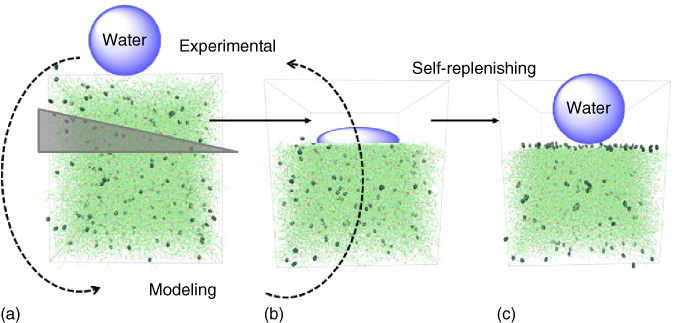
Figure 14.13 Schematic of the dual experimental–simulation approach used to investigate self‐replenishing functional polymeric coatings in a loop‐feeding process.
14.6.1 Low Surface Energy (Hydrophobic) Polymeric Coatings
In order to control and optimize self‐replenishing ability, the first aim was to understand how the low surface energy films are initially formed, how the surface segregation occurs, and which parameters can be tuned to control it.
The investigations therefore started with the study of surface segregation occurring during film formation (i.e. during crosslinking with a polyisocyanate crosslinker) of model low surface energy polyurethane polyester systems [150]. For this purpose, several crosslinked polymeric films were prepared according to methods described in the literature [64]. Well‐defined poly(ε‐caprolactone) (PCL)‐based oligomer precursors were used to build the crosslinked bulk matrix (Figure 14.14a, 1EXP). These precursors consisted of three‐armed hydroxyl‐functionalized polyesters, which were synthesized by ring‐opening polymerization (ROP) with controlled degree of polymerization (DP) (TMP–PClx). The low surface energy polymeric dangling ends consisted of perfluoroalkyl‐end‐capped linear polyesters, also prepared by ROP with controlled functionality and DP (F17C 8PCLy, Figure 14.14a, 2EXP).

Figure 14.14 (a) Low surface energy films components (EXP = experimental and SIM = simulation): (1) polyester precursor (TMP–PCLx, x = 3n, where n is the number of caprolactone (CL) units per arm), (2) perfluorinated dangling chains (F17C8–PCLy, y = total number of CL units), and (3) tri‐isocyanate crosslinker and (b) simulation box snapshots: complete system (A) and details of the air–film interface (B) and bulk (C). Sources: Esteves et al. 2014 [70]. Adapted with permission of AIP Publishing and Esteves et al. 2014 [150]. Adapted with permission of the Royal Society of Chemistry.
In this approach the miscibility of the fluorinated tail with nonfluorinated components is enhanced by introducing a spacer between the perfluoroalkyl group and a reactive group to allow more f1uorinated species to be present in the bulk of the film. The spacer is based on PCL, which provides the fluorinated tail with enough mobility when incorporated into crosslinked networks. In case of surface damage that leads to the loss of the top layers, fluorinated tails from sublayers will be able to reorient themselves to minimize the air/film interfacial energy, owing to the flexibility of the PCL spacer.
In parallel, the network components were simultaneously investigated by a coarse‐grained simulation method known as dissipative particle dynamics (DPD) [151, 152]. In this method, groups of atoms (typically a functional group) are represented by so‐called beads, for which bonded and nonbonded interactions are estimated by a map on Flory–Huggins theory. The polymer precursor (TMP–PCLx), the fluorinated dangling ends (F17C 8PCLy), and the crosslinker were represented by different number of beads, with equal volume considerations (Figure 14.14a, 1SIM, 2SIM, and 3SIM, respectively). The simulation box was built up as a 3D cube with periodic boundary conditions. Polymer and crosslinker molecules were placed randomly in the box, keeping the overall reduced density at ρ = 3, and a layer of air beads was placed at the top of the polymer film, creating the polymer–air interface. Finally, the polymer film was crosslinked and equilibrated (Figure 14.14b).
The self‐replenishing behavior of fluorinated species was demonstrated by studying the distribution profile of the fluorinated components angle resolved by XPS in combination with microtoming [149], which was used as a way to introduce controlled damage. As shown in Figure 14.15, the F/C molar ratio appears to be constant throughout the coating, indicating a relatively homogeneous distribution of fluorinated species in the bulk of the film. What is significant is that for each slice, the F/C ratio in the top 5 nm is about 60% greater than that in the top 10 nm of the slice. The greater F/C ratio in the top 5 nm clearly suggests that the replenishing of fluorinated tails already takes place after the microtoming and before the XPS measurements: otherwise the F/C ratios in the top 5 and 10 nm would be the same for the slices from the bulk of the film. Since the Tg ≅ −20 °C, it is not surprising that self‐replenishing of the fluorinated species takes place at room temperature after microtoming. In this respect, the replenishing behavior can be regarded as autonomous and spontaneous, since the trigger and driving force are intrinsically available. The recreation of new air interfaces resets an energy difference that further promotes the mobility of the dangling chains toward the damaged areas.

Figure 14.15 F/C ratios at a probe depth of 5 and 10 nm after cutting slices of 30 μm from a 200 μm thick polyurethane coating containing perfluorooctyl–PCL with 1 wt% of fluorine in bulk.
For the simulations, the damage was mimicked by removing the top layers in the simulation box, replacing it by a new air layer, and equilibrating the structure thereafter (Figure 14.16b). Using results obtained for the F/C ratio before and after damage and self‐replenishing, the self‐replenishing efficiency (SRE) was estimated from the experimental and simulation data (Table 14.2).

Figure 14.16 Simulation of fluorine‐beads profile as function of z‐coordinate. (a) Top layer: Damage and multiple self‐replenishing of films prepared from TMP–PCL24 and 2 wt% of fluorine (via F17C8–PCL16 dangling chains). Spheres: Before the damage. Open stars and triangles: After subsequent damages and self‐replenishing (i.e. after equilibration). (b) Snapshots of (A) bulk polymer film before damage, (B) polymer film immediately after damage, and (C) damaged polymer film after equilibration (self‐replenishing). Source: Esteves et al. 2014 [70]. Adapted with permission of AIP Publishing.
Table 14.2 Self‐replenishing efficiency (SRE) based on water advancing CA and F/C atomic ratio measurements (experimental) or calculations (simulation), before and after damage.
Source: Esteves et al. 2014 [70]. Adapted with permission of AIP Publishing.
| TMP–PCLx | F17C8–PCLy | SRE (%) based on F/C ratio | SRE (%) based on F/C ratio | SRE (%) based on CA |
| x = | y = | Experimental | Simulation | Experimental |
| 24 | 8 | 118 ± 13 | — | 90 ± 7 |
| 24 | 12 | 117 ± 11 | 80 ± 10 | 80 ± 3 |
| 24 | 16 | 139 ± 26 | 78 ± 14 | 84 ± 3 |
| 24 | 18 | 123 ± 28 | — | 86 ± 3 |
| 24 | 22 | — | 74 ± 23 | — |
| 24 | 24 | 123 ± 8 | — | 83 ± 3 |
| 18 | 16 | 116 ± 9 | 80 ± 11 | 92 ± 2 |
| 24 | 16 | 139 ± 26 | 85 ± 11 | 84 ± 3 |
| 36 | 16 | 163 ± 59 | 87 ± 13 | 83 ± 4 |
| 48 | 16 | — | 82 ± 10 | 75 ± 3 |
In both approaches, the films showed an enrichment with fluorine species at the surface after damage (i.e. above the theoretical bulk value of 0.02). In the simulations all films recovered up to 75–80% of their initial F/C value. In the experimental approach, a full replenishment of the F/C atomic ratio was observed for the damaged and replenished films. In fact, values larger than 100% were obtained. It should be mentioned, however, that F/C atomic ratio determined by XPS for the microtomed surfaces contains additional error sources as compared with the nondamaged surface [70]. Ultimately, the experimental SRE was evaluated by the capability of the films to recover their initial function, that is, their hydrophobicity, assessed here by the water CA. Using this criterion, all the films were able to recover up to 90% of their original CA. In Figure 14.16a the simulation results provide a clear example of the multiple recovery of the fluorinated components (F‐beads) at the top layers of the polymer film, created after two consecutive damages. The self‐replenishing ability, however, decreases with the increasing length of the polymeric segments in‐between crosslinks of the bulk network, from ≅92% down to ≅75%. This was mainly attributed to the use of PCL‐based systems, which have been reported to have large CA hysteresis due to surface rearrangements or suffer from permanent damage on the network by enduring contact with water, for example, by hydrolyses of the ester bonds. Another interesting aspect that can be seen in Figure 14.16a is the formation of a new depletion zone just beneath the new F‐beads‐enriched surface layer, which was estimated to be ≅5 nm, and the presence of the clusters, as described in the study of the initial formation of the crosslinked systems.
It should be noticed, however, that the intrinsic mobility of the end chains as well as of the bulk material, that is, their Tg, is critical for efficient self‐replenishing and acceptable time scales involved in the recovery. Phase‐separated polymer systems made of PDMS‐grafted‐(polystyrene‐block‐poly(maleic anhydride) (PSMA) (co)polymers have been reported to fully recover their initial hydrophobicity in a few tens of minutes, while the poly(urethane polyester) systems containing the perfluorinated dangling chains took about 2 h to recover [150], both at room temperature. This difference has been mainly attributed to the presence of the PDMS chain grafts (Tg ≅ −128 °C) in the first system, which contribute for surface rearrangement with a very soft and mobile component in a rather stiff bulk PSMA phase (Tg ≅ +162 °C) [150].
14.6.2 Time Recovery of the Surface Self‐replenishing
Knowing the typical time response of surface reorganization is critical to design a material in such a way that the surface functionality and high performance of the material can be maintained throughout its life cycle. Hence, the kinetics of the surface recovery of these self‐replenishing films was investigated.
For this purpose a dynamic recovery contact angle (DRCA) method was designed with which the time frames involved in surface rearrangements of polymer films can be estimated (Figure 14.17a). The DRCA method uses a simple, noninvasive, and reconstructive approach, based on the sequential exchange of the polymer surface contact between a probe liquid (water) and air to estimate the approximated time period te needed for the surface to recover from damage, that is, for the surface to be replenished with chemical groups similar to the ones present in the surface before the damage.

Figure 14.17 Estimation of the time of recovery for self‐replenishing films. (a) Illustration of the DRCA method [70] and (b) advancing (solid symbols) and receding (open symbols) water contact angle (CA) versus air exposure time te for films with 2 wt% of fluorine: (•) Rf8‐PCL8, (▴) Rf8‐PCL16, and (⋆) Rf8‐PCL24. The time of air exposure te (in minutes) was converted to log scale for easier visualization. The CAadv at log time = 0 min corresponds to the CA value measured at t0, immediately after one night immersed in water. Source: Esteves et al. 2014 [70]. Adapted with permission of AIP Publishing.
Polymer films were prepared with an overall content of 2 wt% of fluorine and dangling chains with different lengths, that is, DP from 8 to 24. After immersion in distilled water for one night (t0), all the films showed an initial (maximum) drop of the CA in the order of 30–40° (Figure 14.17b), as compared with the original dry values of about 100–110°. This clearly indicates the enforced orientation of the perfluorinated components toward the bulk. Further on, the DRCA analysis showed that all the film surfaces rearrange toward higher hydrophobicity, with a characteristic time of recovery (te) of about 2 h (Figure 14.17b), at room temperature [71]. The CA values after recovery are still on average 5° below the original values (Figure 14.17b). This incomplete recovery is attributed to easy penetration of water into the slightly hydrophilic PCL‐based polymer network, leading to permanent damages/changes of the network segments, for example, through hydrolysis of the ester bonds of the bulk polymers or the polymeric spacer of the dangling chains, as indicated before.
The DRCA results obtained for the receding contact angles (CArec) were, however, very different. For the same recovery time, the final CArec were far lower than the original values. Typically, the CArec measurements, although short in time scale with respect to the total recovery time, already include some initial response of the surface, which was prewet when measuring the advancing CAadv, that is, the recovery time is nearly reset to zero by each CAadv measurement. Hence, the CArec do not provide reliable data for the reconstructive approach as used in the DRCA method.
Finally, the surface recovery of the films with DP 16 and 24 was examined. For these films recovery seemed to proceed slower, attributed to shielding of the hydrophilic groups or restrictions on the polymer spacer local segment mobility that delays the surface reorientation [70].
Generally, the DRCA method is simple, time effective, and versatile and can be further applied with different probe liquids on a wealth of polymeric systems with surface‐tailored chemical groups or polymeric functional materials. However, for polymeric systems sensitive to the probe liquid (in this case water), the time responses may be (highly) convoluted with other effects.
14.6.3 Surface‐structured Superhydrophobic Polymeric Coatings
Many efforts have been made toward durable and robust functional surfaces [74, 153, 154]. This becomes particularly challenging when the surface functionality depends not only on the surface chemical composition but also on the surface structure (topography) as well. This is the case for self‐cleaning surfaces [155], which rely on a superhydrophobic behavior achieved by the combination of low surface energy components and rough surfaces, typically with nanometer‐ and micrometer‐size features. An important issue with this type of surfaces is their (mechanical) integrity for which several reviews are available [156].
A few self‐healing strategies have been reported to repair surface functionalities on rough surfaces, based on desorption or migration of low surface energy components, previously adsorbed or deposited by CVD methods on porous materials, into the damage loci [72]. In the majority of these cases, a triggering stimulus, such as temperature or moisture, is required to initiate the healing [156]a.
A coarse but rather efficient approach to achieve this is to use low surface energy polymer layers (e.g. PDMS or fluorinated polymers) heavily loaded with inorganic nanoparticles (even largely aggregated) [157, 158]. When the surface is damaged, for example, by minor abrasion or wear, new topographic surfaces are recreated that still contain aggregates and the polymer, thus the superhydrophobic character is retrieved. One of the drawbacks of these approaches is the very high load of aggregates, which results in very rough and opaque coatings, and in some cases rather stiff and brittle polymeric layers that are susceptible to cracking and other mechanical failures.
Li et al. [72] prepared porous polymeric coatings via a layer‐by‐layer method that are composed of poly(allylamine hydrochloride) (PAH), a sulfonated poly‐ether‐ether‐ketone (SPEEK) and poly(acrylic acid), impregnated with a reactive low surface energy component, 1H,1H,2H,2H‐perfluoro‐octyltriethoxysilane (POTS). Upon removal of top layers by an O2 plasma treatment and recreation of new air interfaces, the POTS molecules segregate to the new surfaces recovering the initial low surface energy. Due to the porosity of the coatings, the damaged surfaces are rough, thus the initial superhydrophobic character is restored. Note that superhydrophobic surfaces rely on the combination of low surface energy combined with a rough topography. In this case, the driving force for the relocation of the healing agents is the energy difference between the coating's surface and bulk. A certain humidity level is necessary to trigger the healing agents (POTS molecules) mobility.
Using the same approach as discussed in Section 14.6.1, surface‐structured coatings, which can recover spontaneously their surface chemical composition on the new surface structures created upon damage (Figure 14.18), were also studied. The surface structure was built up via chemically bonding silica nanoparticles of two different sizes to the crosslinked network (Figure 14.18a) using all‐in‐one dispersions and a simple one‐step chemical method. The surface repair occurs spontaneously using intrinsic elements of the coatings' bulk. The low surface energy was provided by fluoroalkyl‐modified polymeric dangling chains, also covalently bonded to the crosslinked polymer network (Figure 14.18b).
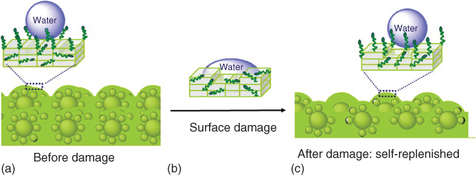
Figure 14.18 Schematic of the self‐replenishing of surface‐structured superhydrophobic coatings, buildup with silica nanoparticles of two different sizes.
When the surface is damaged, the particles in the bulk provide for new surface roughness and the polymeric dangling a chain at the top surface beneath the damage reorient toward the new air–coating interfaces created, recovering the surface chemical composition (Figure 14.18a–c).
The initial morphology of all the coatings showed a homogeneous distribution of the dual‐sized nanoparticles throughout the bulk and a protuberant layer at the air interface, in a raspberrylike morphology (Figure 14.19a,b). AFM revealed the topography details and the existence of a dual‐scale roughness on the micrometer and nanometer range. The surface chemical composition was investigated by XPS, which confirmed the presence of silica nanoparticles and fluoroalkyl‐dangling chains in the top 10 nm layer of the coating [73].

Figure 14.19Experimental evidence of the self‐replenishing of surface‐structured superhydrophobic polymeric coatings after 500 abrasion cycles with sandpaper [71]: SEM images showing the recreation of new surface structures upon the damages inflicted by the sandpaper damaging: (a, b) before damage and (c, d) after damage; (e) static and dynamic water contact angles on dual‐structured coatings with 1.5 wt% of F and Rf8‐PCL16 dangling chains, after damage and self‐replenishing. Source: Esteves et al. 2014 [71]. Adapted with permission of the Royal Society of Chemistry.
To study the self‐replenishing of these structured coatings, the damage that occurs on real applications was mimicked by abrading the surface with sandpaper (400 grit, under constant pressure of 4300 Pa). The surface‐structured coatings with 1.5 wt% of fluorine were further damaged with up to 500 abrasion cycles (in total a layer of ≅90 μm was removed), and the static and dynamic water CAs were evaluated after at each 100 cycles (Figure 14.19e).
Regardless of the harsh damage imposed on the surface, the water CAs remained high, and the CAH decreased considerably (≅10°) (Figure 14.19e). Although the concentration of the fluorinated dangling chains did not seem to be critical for the water CA of the initial structured surface, it was determinant for the self‐replenishment [71]. The enrichment of the initial air interface with low surface energy groups may occur naturally during the crosslinking process, driven by energy differences between the surface and bulk. However, for repetitive replenishment, a sufficient concentration (in this case, ≥1.5 wt% F) of the dangling chains in the bulk crosslinked network was required providing a reservoir of the self‐healing agent.
The morphology of the coatings before and after the abrasion cycles was investigated by SEM. Large‐scale (macroscopic) roughness profiles were induced by the abrasion, and new layers of large and small particles were exposed at the air interface, creating a new micro‐ and nanometer level roughness (Figure 14.19c,d). To infer on the influence of the macroscopic roughness introduced by the abrasion test, coatings prepared with equivalent wt% of F but without particles were also characterized. After 500 abrasion cycles, these reference coatings maintained a relatively constant water CA, showing that the effect of the macroscopic roughness on the surface wettability could be disregarded [71].
Even though the regenerated topography did not show the initial raspberry morphology, the new rough surfaces created were able to entrap sufficient air into the surface structure to maintain a high water CA [71]. These results show the importance of having sufficient topography‐inducing elements (particles) homogeneously distributed in the bulk, so that they can recreate topographies upon repetitive damage. In this case, the recreation of a multiscale surface roughness may even be beneficial for the surface wettability.
The recovery of the chemical composition upon abrasion of the surface‐structured composite coatings was analyzed with XPS. After 500 abrasion cycles the F/C atomic ratio on the top 10 nm layer increases slightly in relation to the initial surface [71], while the Si/C atomic ratio remained approximately constant. These results provide further evidence of the reorientation of the dangling chains, covalently bonded to the polymer layer covering the regenerated topography. Hence, these studies demonstrate that the self‐replenishing effect observed for the structured coatings is most likely a combined result of the regenerated multiscale topography and the spontaneous reorientation of the fluorinated dangling chains at the new air interfaces.
Finally, the role of the different interfaces present in these surface‐structured polymeric coatings and its effect on the self‐replenishing were investigated. Simulations of particle–polymer–particle and air–polymer–particle interfaces (Figure 14.20a,c, respectively) were used to access the distribution profile of the dangling chains at various interfaces. Note that in these simulations, only one size of particles was considered, as the overall size of the silica particles (either a few tens or a few hundreds of nanometers) is irrelevant for the size scale considered (a maximum of a few tens of nanometers). It appeared that the presence of particle interfaces affects significantly the distribution of the low surface energy groups, particularly in the situation where these groups have a strong affinity with the particle surface and are therefore strongly segregated at the particle–polymer interface [74]. Such information is not easily obtained by experimental techniques.
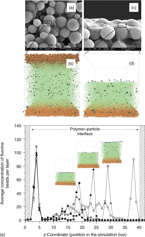
Figure 14.20Experimental: SEM images of the surface‐structured composite coatings: (a) air–coating interface and (b) cross section showing the nanoparticles distribution at the surface and in the bulk of the polymeric layer. Simulation: 3D simulation boxes for (c) the polymer layer sandwiched between two particle surfaces (bulk setup) and (d) polymer film on a particle surface (interface setup). The F‐beads were made larger (4×) and darker for easier visualization. Simulation of multiple self‐replenishing events (interface setup). (e) Plot of the F‐beads profile as function of z‐coordinate (10 DPD units ≈ 7.2 nm): open stars, before the damage and closed symbols, after repeated damages and subsequent self‐replenishing events (i.e. after equilibration). Insets: snapshots of the respective final states of the multiple self‐replenishing events. Source: Lyakhova et al. 2014 [74]. Adapted with permission of John Wiley & Sons.
In order to investigate possible restrictions of the self‐replenishing effect imparted by interfaces, the self‐replenishing was evaluated using the two simulation setups, the interface and bulk as shown in Figure 14.20b,d, respectively. Repeated cuts were mimicked, by removing polymer beads in the top layer, in a direction parallel to the z‐coordinate, toward the particle surface and at different depths of the polymer film (z‐coordinate, 1 DPD unit ≅ 0.72 nm). The presence of a particle–polymer interface, with proper interactions of the fluorinated dangling chains with the particle and/or substrate, allowed the evaluation of the self‐replenishing behavior of a film confined by a surface. This is close to the real conditions where either particles or substrates are always present.
From the profiles of the average concentration of the fluorine‐beads per layer (Figure 14.20e), it can be seen that the height of the F‐beads peak clearly decreases with the increasing depth of cut toward the particle surface. For a polymer layer thickness larger than ≅30–35 nm, the surface segregation is constant, but it starts decreasing significantly when the polymer layer is thinner than ≈30 nm. In these very thin polymer layers, all low surface energy groups are already segregated at the air and particle interfaces, and the bulk does not serve as a reservoir anymore for self‐replenishing. Hence, for these systems it was estimated that after a damage polymer layers of thickness less than 30 nm, the effectivity of self‐healing decreases significantly [74]. In spite of this limiting thickness factor, its influence on the self‐replenishing of the systems studied was fortunately rather small, since only a thin, approximately 30 nm polymer layer is required to reach an optimum self‐replenishing ability. This is also the reason why the self‐replenishing of the new structured surfaces created by the damage is so efficient. These findings are in agreement with the literature about reorganization and rearrangements of functional groups on polymer surfaces [159], which states that it occurs by the exchange and movement of chemical groups between the top surface layers over a distance of only a few nanometers.
This research has led to an in‐depth understanding of the self‐replenishing of hydrophobic and superhydrophobic polymeric coatings, which may find many applications in the automotive and aeronautics fields as self‐cleaning coatings. The design principles and guidelines for the optimization of the materials properties, originating from the experimental–simulation approach, can be further extended to other self‐healing surface‐dependent functionalities, for example, antibacteria, anti(bio)fouling, or drag‐reduction surfaces, maintaining their high performance level through an extended life cycle with low cost and energy demand for maintenance and surface repair.
14.6.4 Further Remarks
Using a similar self‐replenishing principle as discussed in the previous section, Kuroki et al. [75] reported recently self‐healing AF coatings. A polymer system consisting of a pH‐responsive poly(2‐vinylpyridine) (PVP) network was grafted with poly(ethylene oxide) (PEO) chains (brushes), both to the surface and inside the host network material (3D grafting). PEO‐surface grafted polymer films have been extensively investigated for their AF behavior, that is, low protein adhesion properties. To mimic surface damage, a substantial fraction of the top polymer layers was removed on the PVP–PEO 3D‐grafted polymers, and sequentially flushed with a solution at physiological conditions (pH 7.4 and 37 °C). The PVP–PEO polymer networks showed a fourfold increase in longevity of the AF behavior, as compared with polymer films in which only the surface was grafted with PEO brushes [75]. Also in this case, the healing of the surface properties was attributed to the spontaneous surface replenishment with PEO chain segments stored inside the film in proximity of the interface, driven by an emerging gradient in a chemical potential.
The self‐healing principles applied so far to hydrophobic [64, 70] superhydrophobic [73, 74] and AF coatings [75] can be expected to expand to coatings with other functionalities, such as antibacteria, antifog, anti‐icing, or even drag reduction, which will find application in new technological areas, for example, biomedical, optical devices, microfluidics, and microelectronics. Although hydrophilic and superhydrophilic surfaces are equally relevant for many functional coatings, no studies seem to have been reported so far for self‐healing (super)hydrophilic polymeric coatings.
Another interesting possibility for repairing surface functionalities is using reactive chain ends for reestablishing molecular interactions across surfaces/interfaces. This principle has been reported to repair broken bonds in the main chain of bulk networks, for example, by Imaizumi et al. [160] on poly(phenylene ether) (PPE) composite materials that recovered spontaneous by a reaction of the chain ends with a copper/amine complex catalyst added to the system and by Urban and Ghosh [124] on polyurethane matrices with additional nonreacted oxetane groups that were further reacted on damaged sites upon UV irradiation.
In functional polymeric coatings, such mechanisms could assist, for instance, the readhesion of films at the polymer–substrate interfaces, the rebonding of layers on multilayer coatings systems, or the firm reattachment of opposite faces of a crack once they get into contact. In this case, the reactive groups should only be consumed once they reach an interface, and sufficient chain mobility should be granted by tailoring the polymer chain reactive segments.
Extrinsic self‐healing approaches have understandably been less investigated for the recovery of surface properties. There could be, however, interesting possibilities using extrinsic self‐healing agents, such as using the controlled release of biocides encapsulated in healing reservoirs, which could reduce the adhesion of (bio)foulants to the surface, hence, extending the AF performance of the polymeric coatings [161]. In any case, surface segregation of the healing components should always be possible or stimulated by additional means, for example, via the increase of mobility by heating, via swelling with solvents, or via washing with solutions.
14.7 Scenarios for Further Options
One thing is for sure: we will see more examples of commercial self‐healing coatings in the coming years than the automotive clear coats now breaching their way to the market. It remains still doubtful whether our car will ever be able to self‐heal deep scratches, but then what can we expect? Will there also be new and more sophisticated self‐healing mechanisms? The examples of self‐healing mechanisms as discussed in the previous sections definitely do not cover the entire potential of conceivable self‐healing mechanism for polymer coatings and thin films. What more options will be found useful in the (near) future? We cannot give a comprehensive answer to that question, but we can point to a number of mechanisms that we think could be of value but have not been tried to an appreciable extent yet. It is clear that surface tension is the most important driving force for healing of polymer surfaces and interfaces between polymers. As a first general mechanism, the surface or interfacial tension could be used for more than just material transport of surface active groups: would it not be nice to have some reactive groups left in the network that enrich at damaged interfaces and are able to form new bonds across the interface? Delamination could be undone, and cracks could disappear.
Another general mechanism is decoupling of functions. In many respects the demands on a material are of an opposing nature. Separation of the contradicting functions in two (or more) different layers and/or materials could provide a solution for self‐healing abilities that do not withstand the normally expected coating properties of decoration and protection. We will deal with these options in the sequel.
14.7.1 Residual Network Reactivity
A full conversion of all reactive groups during network formation is never accomplished in traditional thermoset polymer materials, simply because of reasons of nonexact stoichiometry (if at least two different, but complementary functional groups come together), kinetics, or hindered molecular mobility after the gel point or even a vitrification point. Leftover reactive groups could be located on dangling ends of the network or even located on unreacted polymer segments (oligomers). But could we not use this fact deliberately and design the thermoset formulation such that a considerable proportion of the reactive oligomers or chain ends is not attached to the network during the curing but left untouched for later use? They could then be used to form new bonds in a damaged area, as a reservoir for self‐healing capability, their segregation driven by the surface tension.
It has been shown experimentally [162] that there is a difference between the surface tension γ∞ of a fully crosslinked polymer and the surface tension of the same polymer γN still containing oligomers. If N denotes the DP, an approximate relation, given by Legrand and Gaines (see Chapter 7), is
where x = 2/3 has been observed experimentally. Theoretically an exponent x = 1/2 is expected [163] for the so‐called normal attraction regime, which is due to a decrease in entropy of the chain ends when they approach a surface. The entropy decrease leads to a certain enrichment of chain ends to the surface and may be either enhanced or counteracted by enthalpy effects. The increase in surface tension with increasing DP indicates that, after a nearly full cure of a certain material system, segregation of oligomers to the interface is limited. For options at later stage to cure a bit further, a certain minimal amount of oligomers is thus required.
It will be clear, though, that there are also limitations to this approach. What if the extra reactive groups are consumed by side reactions? Are the groups that did react during cure sufficient for obtaining basic properties include weatherability? Moreover, the theoretical expectation of chain end segregation has not been confirmed unequivocally by experiments. For a uniform distribution of chain ends, the value for x is 1. The experimentally observed value x = 2/3 may indicate a transition between these two behaviors or be due to segregation of small molecule impurities.
14.7.2 Segregation of Interactive Chain Ends
In Section 14.5, the principles of self‐replenishing have been demonstrated. The self‐replenishing species were either network‐bound low surface energy groups or unbound low molecular weight species. Could the same mechanism be also used to segregate chain ends to a damaged interface that are able to interact with similar chain ends at the opposite side of the damaged interface and, hence, to reestablish molecular interaction across the interface? Such a mechanism could result in readhesion of a delaminated coating or film, or even firmly reattach the opposite faces of a crack, whereas such phenomena are not possible with conventional polymer network materials.
Since the entropy of the chain ends results in a limited increase of chain ends present in the surface, in order to have sufficient segregation to be able to entangle with chains from the opposite, homointerface surface and enthalpy must help the segregation. This can be cloned by modifying the chain ends with strongly surface favoring groups, such as fluorine‐ or silicone‐based species. However, the segregated groups must also be able to react or at least interact with the opposite surface in order to be able to induce (self‐)healing. Since reactive groups are usually less prone to surface segregation than the aforementioned groups, sufficient flexibility in the end chains should be ensured.
14.7.3 Multilayer and Graded Coatings graded coatings"?>
As elaborated in Section 14.1, the demands on coatings are multiple and often of opposite nature. The solution for this is, of course, decoupling of the effects involved. To realize this decoupling the coating must be multilayered or, less easy, graded. In the case of coatings on a stiff substrate, a well‐cured and, therefore, hard coating may be applied to the substrate first and subsequently a soft, and therefore, self‐healing top layer may be added. Although the hard layer obviously cannot self‐heal, the top layer can. For flexible substrates this approach will not work since then fracture of the hard coating will occur upon bending. A related but slightly different approach is to use graded coatings with a gradient from hard to soft from the substrate to the top. Obviously, these approaches are at the expense of a more elaborate application procedure as compared with a single‐layer coating, probably resulting in a more expensive solution.
14.8 Final Remarks
After having discussed in this chapter several approaches with potential for self‐healing polymeric coatings, it will be clear that the field is complex. First, it should be noted that the selection of a self‐healing approach and its final level of success depends fully on its appropriateness for a given application and functionality.
Therefore, certain extrinsic approaches, such as the use of vascular networks or fibers, do not seem very likely to make it to real polymeric coatings applications mainly due to the detrimental impact on other properties of the coatings and inherent fabrication limitations. Other extrinsic concepts such as liquid encapsulation and the use of doped inorganic nanoparticles have already reached promising results so as to reach the industrial sector. Intrinsic approaches appear to be the most promising, namely, using thermally reversible interactions or self‐segregated molecular chains, in the particular case of functional polymeric coatings. With these approaches multiple healing events can be reached, but with limitations due to the temperatures or other stimuli required and possible side effects on other properties (e.g. lower mechanical stability).
In spite of the substantial progress toward self‐healing polymeric coatings, interesting queries have not found optimal solutions yet: how could the coating material distinguish accurately between nondamaged and damaged areas? How to control precisely the transport or the mobility of desired healing agent to damaged areas only, without affecting the neighboring nondamaged, coated, and uncoated areas? How can we visualize the self‐repairing state of a coating at a specific time of use? Or how can we introduce multiple healing mechanisms that will simultaneously address damages across several scales? Moreover, the longevity of such coatings (including the effect of weathering and (mechanical) stability) has to be shown (see, e.g. [156]) and for which design considerations have been provided [164, 165]. Finally, large‐scale fabrication for practical applications remains an issue [166, 167].
Apart from improving existing or inventing new mechanisms, a beneficial next step for a successful implementation of self‐healing mechanisms in polymeric coatings is the use of systems based on detection–actuation–healing, for example, by the implementation of new visual damage‐detecting mechanisms, such as color change, or specific and location‐targeted driving forces, such as inclusion of charge gradients.
In spite of these prospects, there is still a need to dedicate more attention to the in‐depth understanding of the reported self‐healing mechanisms, which may require combined experiments, simulations, and mathematical modeling approaches, so that we can gain a better control over their implementation and optimization for (functional) polymeric coatings.
References
- 1 Feng, W., Patel, S.H., Young, M.Y. et al. (2007). Adv. Polym. Technol.26: 1.
- 2 Baghdachi, J. (2009). Smart coatings. In: Smart Coatings II (ed. T. Provder and J. Baghdachi), 3. Washington, DC: American Chemical Society.
- 3 van Benthem, R.A.T.M., Ming, W. and de With, G. (2007). Self healing polymer coatings. In: Self Healing Materials (ed. S. van der Zwaag), 139. Springer.
- 4 Esteves, A.C.C. and García, S.J. (2015). Self‐healing polymeric coatings. In: Functional Polymer Coatings: Principles, Methods, and Applications (ed. L. Wu and J. Bagdachi) Chapter 4, 133. Wiley.
- 5 Ghosh, S.K. (2006). Functional coatings and microencapsulation: a general perspective. In: Functional Coatings (ed. S.K. Ghosh), 1. Weinheim: Wiley‐VCH.
- 6 van der Zwaag, S. ed. (2007). Self‐healing Materials: an Alternative Approach to 20 Centuries of Materials Science. Dordrecht: Springer.
- 7 Yang, Y. and Urban, M.W. (2013). Chem. Soc. Rev.42: 7446.
- 8 Murphy, E.B. and Wudl, F. (2010). Prog. Polym. Sci.35: 223.
- 9 Wu, D.Y., Meure, S. and Solomon, D. (2008). Prog. Polym. Sci. 33: 479.
- 10 Garcia, S.J., Fischer, H.R. and van der Zwaag, S. (2011). Prog. Org. Coat.72: 211.
- 11 Esteves, A.C.C. and de With, G. (2016). Self‐replenishing polymeric coatings: repairing surface functionalities. In: Self Healing Materials (ed. S. van der Zwaag and E. Brinkman), 187. Amsterdam: IOS Press.
- 12 Garcia, S.J. (2014). Eur. Polym. J.53: 118.
- 13 Williams, K.A., Dreyer, D.R. and Bielawski, C.W. (2008). MRS Bull.33: 759.
- 14 Syrett, J.A., Becer, C.R. and Haddleton, D.M. (2010). Polym. Chem.1: 978.
- 15 Yang, J.L., Keller, M.W., Moore, J.S. et al. (2008). Macromolecules41: 9650.
- 16 Huang, M.X. and Yang, J.L. (2011). J. Mater. Chem.21: 11123.
- 17 Jackson, A.C., Bartelt, J.A., Marczewski, K. et al. (2011). Macromol. Rapid Commun.32: 82.
- 18 Blaiszik, B.J., Caruso, M.M., McIlroy, D.A. et al. (2009). Polymer50: 990.
- 19 Toohey, K.S., Sottos, N.R. and White, S.R. (2010). Exp. Mech.49: 707.
- 20 Hamilton, A.R., Sottos, N.R. and White, S.R. (2010). Adv. Mater.22: 5159.
- 21 Wagener, K.B., Engle, L.P. and Woodard, M.H. (1991). Macromolecules24: 1225.
- 22 Meier‐Westhues, U. Mechtel, M., Klimmasch, T. and Tillack, J. (2006). www.bayercoatings.com (accessed 14 November 2006) (see also http://www.virtualpu.com/uploads/user_doc_attachment/user_comp_doc0.86.0 (accessed 29 January 2018)).
- 23 Lv, L.P., Zhao, Y., Vilbrandt, N. et al. (2013). J. Am. Chem. Soc.135: 14198.
- 24 Dispinar, T., Colard, C.A.L. and Du Prez, F.E. (2013). Polym. Chem.4: 763.
- 25 Tournilhac, F., Cordier, P., Montarnal, D. et al. (2010). Self‐healing supramolecular networks. In: Polymer Networks: Synthesis, Properties, Theory and Applications (ed. K.S. Patrikios), 84. Weinheim: Wiley‐VCH.
- 26 Cordier, P., Tournilhac, F., Soulie‐Ziakovic, C. and Leibler, L. (2008). Nature451: 977.
- 27 Canadell, J., Goossens, H. and Klumperman, B. (2001). Macromolecules44: 2536.
- 28 Pepels, M., Filot, I., Klumperman, B. and Goossens, H. (2013). Polym. Chem.4: 4955.
- 29 (a) White, S.R., Sottos, N.R., Geubelle, P.H. et al. (2001). Nature 409: 794.(b) Rule, J.D., Brown, E.N., Sottos, N.R. et al. (2005). Adv. Mater. 17: 205.(c) Cho, S.H., Andersson, H.M., White, S.R. et al. (2006). Adv. Mater. 18: 99.
- 30 Kumar, A. and Stephenson L.D. (2006). Self‐healing coatings using microcapsules containing film formers and lead dust‐suppression compounds. US Pat. Appl. Publ. 2006, 2006042504.
- 31 Toohey, K.S., White S.R. and Sottos, N.R. (2005). Proc. 2005 SEM Ann. Conf., Portland, OR, USA (7–9 June 2005), p. 241.
- 32 Mookhoek, S.D., Fischer, H.R. and van der Zwaag, S. (2009). Comput. Mater. Sci.47: 506.
- 33 Dry, C.M. and Sottos, N.R. (1993). Passive smart self‐repair in polymer matrix Composites. In: Proc. SPIE, Smart Structures and Materials, vol. 1916 (ed. K. Varadian), 438. Bellingham, Washington.
- 34 Pang, J.W.C. and Bond, I.P. (2005). Comput. Sci. Technol.65: 1791.
- 35 Liu, H.A., Gnade, B.E. and Balkus, K.J. (2008). Adv. Funct. Mater.18: 3620.
- 36 Mookhoek, S.D., Fischer, H.R. and van der Zwaag, S. (2012). Compos. A Appl. Sci. Manuf.43: 2176.
- 37 Nesterova, T. (2012). Self‐healing anti‐corrosive coatings. PhD thesis. Technical University of Denmark.
- 38 Mookhoek, S.D., Mayo, S.C., Hughes, A.E. et al. (2010). Adv. Eng. Mater.12: 228.
- 39 Caruso, M.M., Delafuente, D.A., Ho, V. et al. (2007). Macromolecules40: 8830.
- 40 Garcia, S.J., Fischer, H.R., White, P.A. et al. (2011). Prog. Org Coat.70: 142.
- 41 Kumar, A., Stephenson, L.D. and Murray, J.N. (2006). Prog. Org. Coat.55: 244.
- 42 Samadzadeh, M., Boura, S.H., Peikari, M. et al. (2011). Prog. Org. Coat.4: 383.
- 43 Sugama, T. and Gawlik, K. (2003). Mater. Lett.57: 26.
- 44 Rey, R., Javierre, E., Garcia, S.J. et al. (2012). Surf. Coat. Technol.206: 2220.
- 45 Micciche, F., Fischer, H., Varley, R. and van der Zwaag, S. (2008). Surf. Coat. Technol.202: 3346.
- 46 Bohm, S., McMurray, H.N., Powell, S.M. and Worsley, D.A. (2001). Mater. Corrosion‐Werkstoffe und Korrosion52: 896.
- 47 Buchheit, R.G., Guan, H., Mahajanam, S. and Wong, F. (2003). Prog. Org. Coat.47: 174.
- 48 Zheludkevich, M.L., Poznyak, S.K., Rodrigues, L.M. et al. (2010). Corr. Sci.52: 602.
- 49 Shchukin, D.G., Lamaka, S.V., Yasakau, K.A. et al. (2008). J. Phys. Chem.C112: 958.
- 50 Ferrer, E.L., Rollon, A.P., Mendoza, H.D. et al. (2014). Micropor. Macropor. Mater.188: 8.
- 51 Dias, S.A.S., Lamaka, S.V., Nogueira, C.A. et al. (2012). Corros. Sci.62: 153.
- 52 Jardret, V. and Morel, P. (2003). Prog. Org. Coat.48: 122.
- 53 de With, G. (2006). Structure, Deformation, and Integrity of Materials. Weinheim: Wiley‐VCH.
- 54 de Gennes, P.G. (1971). J. Chem. Phys.55: 572.
- 55 Wool, R.P. and O'Connor, K.M. (1981). Polym. Eng. Sci.21: 970.
- 56 Kim, Y.H. and Wool, R.P. (1983). Macromolecules16: 1115.
- 57 Wool, R.P. (2008). Soft Matter4: 400.
- 58 Lin, C.B., Lee, S.B. and Liu, K.S. (1990). Polym. Eng. Sci.30: 1399.
- 59 Wang, P.P., Lee, S. and Harmon, J.P. (1994). J. Polym. Sci. B Pol. Phys. 32: 1217.
- 60 Kawagoe, M., Nakanishi, M., Qiu, J. and Morita, M. (1997). Polymer38: 5969.
- 61 Hsieh, H.C., Yang, T.J. and Lee, S. (2001). Polymer42: 1227.
- 62 Liu, C.K., Yang, T.J., Shen, J.S. and Lee, S. (2008). Eng. Fract. Mech.75: 4876.
- 63 Wu, T. and Lee, S. (1994). J. Polym. Sci. B Pol. Phys.32: 2055.
- 64 Dikić, T., Ming, W., Thüne, P. et al. (2008). J. Polym. Sci.A46: 218.
- 65 (a) Bosman, A.W., Sijbesma, R.P. and Meijer, E.W. (2004). Mater. Today 7: 34.(b) Folmer, B.J.B., Sijbesma, R.P., Versteegen, R.M. et al. (2000). Adv. Mater 12: 874.(c) Sijbesma, R.P., Beijer, F.H., Brunsveld, L. et al. (1997). Science 278: 1601.
- 66 Kaufmann, G.B. and Seymour, R.B. (1990). J. Chem. Ed.67: 422.
- 67 (a) Perrera, D.Y. and van den Eynde, D. (1981). J. Coat. Technol. 53: 39.(b) Perrera, D.Y. and van den Eynde, D. (1981). J. Coat. Technol. 59: 55.(c) Perrera, D.Y. and Oosterbroek, M. (1994). J. Coat. Technol. 66: 55.(d) van der Linde, R., Belder, E.G. and Perrera, D.Y. (2002). Prog. Org. Coat. 40: 215.(e) Piens, M. and de Deurwaerder, H. (2001). Prog. Org. Coat. 43: 18.
- 68 Scott, T.F., Schneider, A.D., Cook, W.O. and Bowman, C.N. (2005). Science108: 1615.
- 69 Yufa, N.A., Li, J. and Sibener, S.J. (2009). Polymer50: 2630.
- 70 Esteves, A.C.C., Lyakhova, K., van Riel, J.M. et al. (2014). J. Chem. Phys.149: 140.
- 71 Esteves, A.C.C., Gunbas, I.D., van Riel, J.M. et al. (2014). RSC Adv.4: 20094.
- 72 Li, Y., Li, L., and Sun, J.Q. (2010). Angew. Chem. Int. Ed.49: 6129.
- 73 Esteves, A.C.C., Luo, Y., van de Put, M.W.P. et al. (2014). Adv. Funct. Mater.24: 986.
- 74 Lyakhova, K., Esteves, A.C.C., van de Put, M.W.P. et al. (2014). Adv. Mater. Interf.1: 1400053.
- 75 Kuroki, H., Tokarev, I., Nykypanchuk, D. et al. (2013). Adv. Funct. Mater.23: 4593.
- 76 Chen, X.X., Dam, M.A., Ono, K. et al. (2002). Science295: 1698.
- 77 Chen, X.X., Wudl, F., Mal, A.K. et al. (2003). Macromolecules36: 1802.
- 78 Murphy, E.B., Bolanos, E., Schaffner‐Hamann, C. et al. (2008). Macromolecules41: 5203.
- 79 Tian, Q., Yuan, Y.C., Rong, M.Z. and Zhang, M.Q. (2009). J. Mater. Chem.19: 1289.
- 80 Scheltjens, G., Brancart, J., De Graeve, I. et al. (2011). J. Therm. Anal. Calorim.105: 805.
- 81 Tian, Q.A., Rong, M.Z., Zhang, M.Q. and Yuan, Y.C. (2010). Polym. Int.59: 1339.
- 82 Zhang, Y., Broekhuis, A.A. and Picchioni, F. (2009). Macromolecules42: 1906.
- 83 Canary, S.A. and Stevens, M.P. (1992). J. Polym. Sci. A‐Pol. Chem.30: 1755.
- 84 Kavitha, A.A. and Singha, N.K. (2007). J. Polym. Sci. A Polym. Chem.45: 4441.
- 85 Liu, Y.L. and Chen, Y.W. (2007). Macromol. Chem. Phys.208: 224.
- 86 Liu, Y.L., Hsieh, C.Y. and Chen, Y.W. (2006). Polymer47: 2581.
- 87 Magana, S., Zerroukhi, A., Jegat, C. and Mignard, N. (2010). React. Funct. Polym.70: 442.
- 88 Toncelli, C., De Reus, D.C., Picchioni, F. and Broekhuis, A.A. (2012). Macromol. Chem. Phys.213: 157.
- 89 Wouters, M., Craenmehr, E., Tempelaars, K. et al. (2009). Prog. Org. Coat.64: 156.
- 90 Yoshie, N., Watanabe, M., Araki, H. and Ishida, K. (2010). Polym. Degrad. Stab.95: 826.
- 91 Peterson, A.M., Jensen, R.E. and Palmese, G.R. (2009). ACS Appl. Mater. Interf.1: 992.
- 92 Kavitha, A.A. and Singha, N.K. (2009). ACS Appl. Mater. Interf.1: 1427.
- 93 Yoon, J.A., Kamada, J., Koynov, K. et al. (2012). Macromolecules45: 142.
- 94 AbdolahZadeh, M., Esteves, A.C.C., van der Zwaag, S. and Garcia, S.J. (2014). J. Polym. Sci. A: Polym. Chem.52: 1953.
- 95 Amamoto, Y., Kamada, J., Otsuka, H. et al. (2011). Angew. Chem. Int. Ed.50: 1660.
- 96 Nicolay, R., Kamada, J., Van Wassen, A. and Matyjaszewski, K. (2010). Macromolecules43: 4355.
- 97 Imato, K., Nishihara, M., Kanehara, T. et al. (2012). Angew. Chem. Int. Ed.51: 1138.
- 98 Yuan, C., Rong, M.Z., Zhang, M.Q. et al. (2011). Chem. Mater.23: 5078.
- 99 Cho, S.Y., Kim, J.G. and Chung, C.M. (2008). Sensors Actuat. B‐Chem.134: 822.
- 100 Chung, C.M., Roh, Y.S., Cho, S.Y. and Kim, J.G. (2004). Chem. Mater.16: 3982.
- 101 Montarnal, D., Cordier, P., Soulie‐Ziakovic, C. et al. (2008). J. Polym. Sci. A Polym. Chem.46: 7925.
- 102 Wietor, J.L., Dimopoulos, A., Govaert, L.E. et al. (2009). Macromolecules42: 6640.
- 103 Nieuwenhuizen, M.M.L., de Greef, T.F.A., van der Bruggen, R.L.J. et al. (2010). Chem. ‐Eur. J.16: 1601.
- 104 Villani, M., Camlibel, C., Deshmuk, Y. et al. (2016). RSC Adv.6: 245.
- 105 Huang, L., Yi, N., Wu, Y. et al. (2013). Adv. Mater.25: 2224.
- 106 Skorb, E.V., Skirtach, A.G., Sviridov, D.V. et al. (2009). ACS Nano (7): 1753.
- 107 Tachino, H., Hara, H., Hirasawa, E. et al. (1993). Macromolecules26: 752.
- 108 Varley, R.J. and van der Zwaag, S. (2008). Acta Mater.56: 5737.
- 109 Kalista, S.J. and Ward, T.C. (2007). J. Roy. Soc. Interface4: 405.
- 110 Kalista, S.J. (2007). Mech. Adv. Mater. Struct.14: 391.
- 111 Kalista, S.J., Pflug, J.R. and Varley, R.J. (2013). Polym. Chem.4: 4910.
- 112 Burattini, S., Colquhoun, H.M., Fox, J.D. et al. (2009). Chem. Commun.44: 6717.
- 113 Burattini, S., Colquhoun, H.M., Greenland, B.W. and Hayes, W. (2009). Faraday Disc.143: 251.
- 114 Corten, C.C. and Urban, M.W. (2009). Adv. Mater.48: 5011.
- 115 South, A.B. and Lyon, L.A. (2010). Angew. Chem. Int. Ed.49: 767.
- 116 Herrmann, W.A., Weskamp, T. and Bohm, V.P.W. (2001). Adv. Organomet. Chem.48: 1.
- 117 Karthikeyan, S., Potisek, S.L., Piermattei, A. and Sijbesma, R.P. (2008). J. Am. Chem. Soc.130: 14968.
- 118 Kersey, F.R., Yount, W.C. and Craig, S.L. (2006). J. Am. Chem. Soc.128: 3886.
- 119 Piermattei, A., Karthikeyan, S. and Sijbesma, R.P. (2009). Nat. Chem.1: 133.
- 120 Vega, J.M., Grande, A.M., van der Zwaag, S. and Garcia, S.J. (2014). Eur. Polym. J.57: 121.
- 121 Chang, J.Y., Do, S.K. and Han, M.l. (2001). Polymer42: 7589.
- 122 Canadell, J., Fischer, H., de With, G. and van Benthem, R.A.T.M. (2010). J. Polym. Sci. A Polym. Chem.48: 3456.
- 123 (a) Otsuka, H., Aotani, K., Higaki, Y. and Takahura, A. (2003). J. Am. Chem. Soc.125: 4604.(b) Higaki, Y., Otsuka, H. and Takahura, A. (2003). Macromolecules 39: 2121.
- 124 Ghosh, B. and Urban, M.W. (2009). Science323: 5920.
- 125 Deng, G.H., Tang, C.M., Li, F.Y. et al. (2010). Macromolecules43: 1191.
- 126 Scheltjens, G., Diaz, M.M., Brancart, J. et al. (2013). React. Funct. Polym.73: 413.
- 127 Zhang, Z.H., Hu, Y.L., Liu, Z.S. and Guo, T.Y. (2012). Polymer53: 2979.
- 128 (a) Gregorovich, B.V., Adamsons, K. and Lin, L. (2001). Prog. Org. Coat. 43: 175.(b) Hara, Y., Mori, T. and Fujitani, T. (2000). Prog. Org. Coat. 40: 39.
- 129 Dössel, K.F. (2006). Proc. Car Body Painting, Berlin (July 2006).
- 130 Cho, S.H., White, S.R. and Braun, P.V. (2009). Adv. Mater.21: 645.
- 131 Koh, E., Baek, S.Y., Kim, N.K. et al. (2014). New J. Chem.38: 4409.
- 132 Fu, J.J., Chen, T., Wang, M.D. et al. (2013). ACS Nano7: 11397.
- 133 Vimalanandan, A., Lv, L.P., Tran, T.H. et al. (2013). Adv. Mater.25: 6980.
- 134 Palaivel, V., Huang, Y. and Van Ooij, W.J. (2005). Prog. Org. Coat.53: 15.
- 135 Shchukin, D.G., Zheludkevich, M., Yasakau, K. et al. (2006). Adv. Mater.18: 1672.
- 136 Bose, R., Lafont, U., Vega, J.M. et al. (2013). Methods to monitor and quantify (self‐)healing in polymers and polymer systems. In: Self‐healing Polymers: from Principles, to Applications (ed. W. Binder), 337. Weinheim: Wiley‐VCH.
- 137 Jorcin, J.B., Scheltjens, G., Van Ingelgem, Y. et al. (2010). Electrochim. Acta55: 6195.
- 138 Garcia, S.J., Markley, T.A., Mol, J.M.C. and Hughes, A.E. (2013). Corros. Sci.69: 346.
- 139 Lamaka, S.V., Zheludkevich, M.L., Yasakau, K.A. et al. (2006). Electrochem. Commun.8: 421.
- 140 Gonzalez‐Garcia, Y., Garcia, S.J., Hughes, A.E. and Mol, J.M.C. (2011). Electrochem. Commun.13: 1094.
- 141 Garcia, S.J., Wu, X.M. and van der Zwaag, S. (2014). Corrosion70: 475.
- 142 Lafont, U., van Zeijl, H. and van der Zwaag, S. (2012). Microelectr. Reliab.52: 71.
- 143 Jin, H.H., Mangun, C.L., Stradley, D.S. et al. (2012). Polymer53: 581.
- 144 Mardel, J., Garcia, S.J., Corrigan, P.A. et al. (2011). Prog. Org. Coat.70: 91.
- 145 Lane, M.W., Roush, A. and Callahan, S.E. (2009). Stress‐Induced Phen. Metalliz.1143: 71.
- 146 Kisin, S., Božovic Vukić, J., van der Varst, P.G.Th. et al. (2007). Chem. Mater.19: 903.
- 147 Božovic Vukić, J., Höppener, S., Kozodaev, D.A. et al. (2006, 1912). Chem. Mater.7.
- 148 (a) Ming, W., Laven, J. and van der Linde, R. (2000). Macromolecules33: 6886.(b) Ming, W., Tian, M., van de Grampel, R.D. et al. (2002). Macromolecules35: 6920.(c) van Ravenstein, L., Ming, W., van de Grampel, R.D. et al. (2004). Macromolecules37: 408.(d) van de Grampel, R.D., Ming, W., van Gennip, W.J.H. et al. (2005). Polymer46: 10531.
- 149 Dikić, T., Ming, W., van Benthem, R.A.T.M. and de With, G. (2006). PCT Int. Appl. WO207: 2170.
- 150 Esteves, A.C.C., Lyakhova, K., van der Ven, L.G.J. et al. (2013). Macromolecules46: 1993.
- 151 Espanol, P. (1997). Europhys. Lett.40: 631.
- 152 Hoogerbrugge, P.J. and Koelman, J.M.V.A. (1992). Europhys. Lett.19: 155.
- 153 Boinovich, L., Emelyanenko, A.M. and Pashinin, A.S. (2010). Appl. Mater. Interf.2: 1754.
- 154 Yu, Y., Zhao, Z.‐H. and Zheng, Q.‐S. (2007). Langmuir23: 8212.
- 155 Parkin, I.P. and Palgrave, R.G. (2005). J. Mater. Chem.15: 1689.
- 156 (a) Xue, C.‐H. and Ma, J.‐Z. (2013). J. Mater. Chem. A1: 4146.(b) Dyett, B.P., Wu, A.H. and Lamb, R.N. (2014). ACS Appl. Mater. Interfaces 6: 18380.(c) Cohen, N., Dotan, A., Dodiuk, H. and Kenig, S. (2016). Mater. Manuf. Process 31: 1143.(d) Scarratt, L.R.J., Steiner, U. and Neto, C. (2017). Adv. Colloid Interface Sci. 246: 133.
- 157 Wu, L., Zhang, J.P., Li, B.C. et al. (2014). J. Colloid. Interface Sci.432: 31.
- 158 Yilgor, I., Bilgin, I., Isik, S. and Yilgor, E. (2012). Polymer53: 1180.
- 159 Wong, D., Jalbert, C.A., O'Rourke‐Muisener, P.A.V. and Koberstein, J.T. (2012). Macromolecules45: 7973.
- 160 Imaizumi, K., Ohba, T., Ikeda, Y. and Takeda, K. (2001). Mater. Sci. Res. Int.7: 249.
- 161 Jamsa, S., Mahlberg, R., Holopainen, U. et al. (2013). Prog. Org. Coat.76: 269.
- 162 Legrand, D. and Gaines, G. (1969). J. Colloid Interface Sci. 31: 162; (1973), 42, 181.
- 163 de Gennes, P.G. (1992). Physics of Polymer Surfaces and Interfaces (ed. I.C. Sanchez), 55. Boston: Butterworth‐Heinemann.
- 164 Golovin, K., Boban, M., Mabry, J.M. and J.M. and Tuteja, A. (2017). ACS Appl. Mater. Interf.9: 11212.
- 165 Huovinen, E., Takkunen, L., Korpela, T. et al. (2014). Langmuir30: 1435.
- 166 Park, S.‐H., Lee, S., Moreira, D. et al. (2015). Sci. Rep.5: 15430.
- 167 Xue, C.‐H., Jia, S.‐T., Zhang, J. and Ma, J.‐Z. (2010). Sci. Technol. Adv. Mater.11: 033002.
Further Reading
- Wu, L. and Bagdachi, J. ed. (2015). Functional Polymer Coatings: Principles, Methods, and Applications. Hoboken, NJ: Wiley.