
7
MAGNETIC CIRCUIT CONCEPTS
The purpose of this chapter is to review some of the basic concepts associated with magnetic circuits and to develop an understanding of inductors and transformers needed in power electronics.
7.1 AMPERE-TURNS AND FLUX
Let us consider a simple magnetic structure of Figure 7.1 consisting of an N-turn coil with a current ![]() , on a magnetic core made of iron. This coil applies
, on a magnetic core made of iron. This coil applies ![]() ampere-turns to the core. We will assume the magnetic field intensity
ampere-turns to the core. We will assume the magnetic field intensity ![]() in the core to be uniform along the mean path length
in the core to be uniform along the mean path length ![]() . The magnetic field intensity in the air gap is denoted as
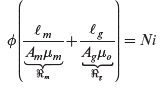
. The magnetic field intensity in the air gap is denoted as ![]() . From Ampere’s law, the closed line integral of the magnetic field intensity along the mean path within the core and in the air gap is equal to the applied ampere-turns:
. From Ampere’s law, the closed line integral of the magnetic field intensity along the mean path within the core and in the air gap is equal to the applied ampere-turns:

FIGURE 7.1 Magnetic structure with an air gap.
In the core and in the air gap, the flux densities corresponding to ![]() and
and ![]() are as follows:
are as follows:
where ![]() . In terms of the above flux densities in Equation (7.1),
. In terms of the above flux densities in Equation (7.1),
Since flux lines form closed paths, the flux crossing any perpendicular cross-sectional area in the core is the same as that crossing the air gap. Therefore,
Substituting flux densities from Equation (7.6) into Equation (7.4),
 (7.7)
(7.7)
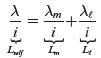
In Equation (7.7), the two terms within the parenthesis equal the reluctance ![]() of the core and the reluctance
of the core and the reluctance ![]() of the air gap, respectively. Therefore, the effective reluctance
of the air gap, respectively. Therefore, the effective reluctance ![]() of the whole structure in the path of the flux lines is the sum of the two reluctances:
of the whole structure in the path of the flux lines is the sum of the two reluctances:
Substituting Equation (7.8) into Equation (7.7),
Equation (7.9) allows the flux ![]() to be calculated for the applied ampere-turns and hence
to be calculated for the applied ampere-turns and hence ![]() , and
, and ![]() can be calculated from Equation (7.6).
can be calculated from Equation (7.6).
7.2 INDUCTANCE L
At any instant of time in the coil of Figure 7.2a, the flux linkage of the coil ![]() , due to flux lines entirely in the core, is equal to the flux
, due to flux lines entirely in the core, is equal to the flux ![]() times the number of turns
times the number of turns ![]() that are linked. This flux linkage is related to the current
that are linked. This flux linkage is related to the current ![]() by a parameter defined as the inductance
by a parameter defined as the inductance ![]() :
:

FIGURE 7.2 Coil inductance.
where the inductance ![]() is constant if the core material is in its linear operating region.
is constant if the core material is in its linear operating region.
The coil inductance in the linear magnetic region can be calculated by multiplying all the factors shown in Figure 7.2b, which are based on earlier equations:
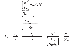 (7.11)
Equation (7.11) indicates that the inductance ![]() is strictly a property of the magnetic circuit (i.e. the core material, the geometry, and the number of turns), provided the operation is in the linear range of the magnetic material, where the slope of its B-H characteristic can be represented by a constant
is strictly a property of the magnetic circuit (i.e. the core material, the geometry, and the number of turns), provided the operation is in the linear range of the magnetic material, where the slope of its B-H characteristic can be represented by a constant ![]() .
.
7.2.1 Energy Storage Due to Magnetic Fields
Energy in an inductor is stored in its magnetic field. From the study of electric circuits, we know that at any time, with a current ![]() , the energy stored in the inductor is
, the energy stored in the inductor is
where [J], for joules, is a unit of energy. Initially assuming a structure without an air gap, such as in Figure 7.2a, we can express the energy storage in terms of flux density, by substituting into Equation (7.12) the inductance from Equation (7.11), and the current from Ampere’s law in Equation (7.1):
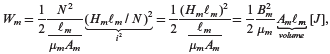 (7.13)
where ![]() , and in the linear region
, and in the linear region ![]() Therefore, from Equation (7.13), the energy density in the core is
Therefore, from Equation (7.13), the energy density in the core is
Similarly, the energy density in the air gap depends on ![]() and the flux density in it. Therefore, from Equation (7.14), the energy density in any medium can be expressed as
and the flux density in it. Therefore, from Equation (7.14), the energy density in any medium can be expressed as
In inductors, the energy is primarily stored in the air gap purposely introduced in the path of flux lines.
In transformers, there is no air gap in the path of the flux lines. Therefore, the energy stored in the core of an ideal transformer is zero, where the core permeability is assumed infinite, and hence ![]() is zero for a finite flux density. In a real transformer, the core permeability is finite, resulting in some energy storage in the core.
is zero for a finite flux density. In a real transformer, the core permeability is finite, resulting in some energy storage in the core.
7.3 FARADAY’S LAW: INDUCED VOLTAGE IN A COIL DUE TO TIME-RATE OF CHANGE OF FLUX LINKAGE
In our discussion so far, we have established in magnetic circuits relationships between the electrical quantity ![]() and the magnetic quantities
and the magnetic quantities ![]() ,
, ![]() ,
, ![]() , and
, and ![]() . These relationships are valid under DC (static) conditions, as well as at any instant when these quantities vary with time. We will now examine the voltage across the coil under time-varying conditions. In the coil of Figure 7.3, Faraday’s law dictates that the time-rate of change of flux-linkage equals the voltage across the coil at any instant:
. These relationships are valid under DC (static) conditions, as well as at any instant when these quantities vary with time. We will now examine the voltage across the coil under time-varying conditions. In the coil of Figure 7.3, Faraday’s law dictates that the time-rate of change of flux-linkage equals the voltage across the coil at any instant:

FIGURE 7.3 Voltage polarity and direction of flux and current.
This assumes that all flux lines link all N-turns such that ![]() . The polarity of the emf e(t) and the direction of
. The polarity of the emf e(t) and the direction of ![]() in the above equation are yet to be justified.
in the above equation are yet to be justified.
The relationship in Equation (7.16) is valid, no matter what is causing the flux to change. One possibility is that a second coil is placed on the same core. When the second coil is supplied by a time-varying current, mutual coupling causes the flux ![]() through the coil to change with time. The other possibility is that a voltage
through the coil to change with time. The other possibility is that a voltage ![]() is applied across the coil in Figure 7.3, causing the change in flux, which can be calculated by integrating both sides of Equation (7.16) with respect to time:
is applied across the coil in Figure 7.3, causing the change in flux, which can be calculated by integrating both sides of Equation (7.16) with respect to time:
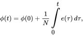 (7.17)
where ![]() is the initial flux at
is the initial flux at ![]() and
and ![]() is a variable of integration.
is a variable of integration.
Recalling Ohm’s law, ![]() , the current direction through a resistor is into the terminal at the positive polarity. This is the passive sign convention. Similarly, in the coil of Figure 7.3, we can establish the voltage polarity and the flux direction in order to apply Faraday’s law, given by Equations (7.16) and (7.17). If the flux direction is given, we can establish the voltage polarity as follows: first, determine the direction of a hypothetical current that will produce flux in the same direction as given. Then, the positive polarity for the voltage is at the terminal, which this hypothetical current is entering. Conversely, if the voltage polarity is given, imagine a hypothetical current entering the positive-polarity terminal. This current, based on how the coil is wound, for example, in Figure 7.3, determines the flux direction for use in Equations (7.16) and (7.17). Following these rules to determine the voltage polarity and the flux direction is easier than applying Lenz’s law (not discussed here).
, the current direction through a resistor is into the terminal at the positive polarity. This is the passive sign convention. Similarly, in the coil of Figure 7.3, we can establish the voltage polarity and the flux direction in order to apply Faraday’s law, given by Equations (7.16) and (7.17). If the flux direction is given, we can establish the voltage polarity as follows: first, determine the direction of a hypothetical current that will produce flux in the same direction as given. Then, the positive polarity for the voltage is at the terminal, which this hypothetical current is entering. Conversely, if the voltage polarity is given, imagine a hypothetical current entering the positive-polarity terminal. This current, based on how the coil is wound, for example, in Figure 7.3, determines the flux direction for use in Equations (7.16) and (7.17). Following these rules to determine the voltage polarity and the flux direction is easier than applying Lenz’s law (not discussed here).
The voltage is induced due to ![]() , regardless of whether any current flows in that coil.
, regardless of whether any current flows in that coil.
7.4 LEAKAGE AND MAGNETIZING INDUCTANCES
Just as conductors guide currents in electric circuits, magnetic cores guide flux in magnetic circuits. But there is an important difference. In electric circuits, the conductivity of copper is approximately ![]() times higher than that of air, allowing leakage currents to be neglected at DC or at low frequencies such as 60 Hz. In magnetic circuits, however, the permeabilities of magnetic materials are, at best, only
times higher than that of air, allowing leakage currents to be neglected at DC or at low frequencies such as 60 Hz. In magnetic circuits, however, the permeabilities of magnetic materials are, at best, only ![]() times greater than that of air. Because of this relatively low ratio, the core window in the structure of Figure 7.4a has “leakage” flux lines, which do not reach their intended destination, which may be, for example, another winding in a transformer or an air gap in an inductor. Note that the coil shown in Figure 7.4a is drawn schematically. In practice, the coil consists of multiple layers, and the core is designed to fit as snugly to the coil as possible, thus minimizing the unused “window” area.
times greater than that of air. Because of this relatively low ratio, the core window in the structure of Figure 7.4a has “leakage” flux lines, which do not reach their intended destination, which may be, for example, another winding in a transformer or an air gap in an inductor. Note that the coil shown in Figure 7.4a is drawn schematically. In practice, the coil consists of multiple layers, and the core is designed to fit as snugly to the coil as possible, thus minimizing the unused “window” area.

FIGURE 7.4 (a) Magnetic and leakage fluxes; (b) equivalent representation of magnetic and leakage fluxes.
The leakage effect makes accurate analysis of magnetic circuits more difficult, requiring sophisticated numerical methods, such as finite element analysis. However, we can account for the effect of leakage fluxes by making certain approximations. We can divide the total flux ![]() into two parts:
into two parts:
- The magnetic flux
 , which is completely confined to the core and links all N turns, and,
 - The leakage flux, which is partially or entirely in air and is represented by an “equivalent” leakage flux
 , which also links all N turns of the coil but does not follow the entire magnetic path, as shown in Figure 7.4b.
In Figure 7.4b, ![]() , where
, where ![]() is the equivalent flux that links all N turns. Therefore, the total flux linkage of the coil is
is the equivalent flux that links all N turns. Therefore, the total flux linkage of the coil is
The total inductance (called the self-inductance) can be obtained by dividing both sides of Equation (7.18) by the current ![]() :
:
 (7.19)
where ![]() is often called the magnetizing inductance due to
is often called the magnetizing inductance due to ![]() in the magnetic core, and
in the magnetic core, and ![]() is called the leakage inductance due to the leakage flux
is called the leakage inductance due to the leakage flux ![]() . From Equations (7.19) and (7.20), the total flux linkage of the coil in Equation (7.18) can be written as
. From Equations (7.19) and (7.20), the total flux linkage of the coil in Equation (7.18) can be written as
Hence, from Faraday’s law in Equation (7.16),
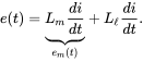 (7.22)
This results in the electrical circuit of Figure 7.5a. In Figure 7.5b, the voltage drop due to the leakage inductance can be shown separately so that the voltage induced in the coil is solely due to the magnetizing flux. The coil resistance ![]() can then be added in series to complete the representation of the coil.
can then be added in series to complete the representation of the coil.

FIGURE 7.5 (a) Circuit representation; (b) leakage inductance separated from the core.
7.4.1 Mutual Inductances
Most magnetic circuits, such as those encountered in inductors and transformers, consist of multiple coils. In such circuits, the flux established by the current in one coil partially links the other coil or coils. This phenomenon can be described mathematically by means of mutual inductances, as examined in circuit theory courses. However, we will use simpler and more intuitive means to analyze mutually coupled coils, as in a flyback converter discussed in Chapter 8 dealing with transformer-isolated DC-DC converters.
7.5 TRANSFORMERS
In power electronics, high-frequency transformers are essential to switch-mode DC power supplies. Such transformers often consist of two or more tightly coupled windings where almost all of the flux produced by one winding links the other windings. Including the leakage flux in detail makes the analysis very complicated and not very useful for our purposes here. Therefore, we will include only the magnetizing flux ![]() that links all the windings, ignoring the leakage flux, whose consequences will be acknowledged separately.
that links all the windings, ignoring the leakage flux, whose consequences will be acknowledged separately.
To understand the operating principles of transformers, we will consider a three-winding transformer, shown in Figure 7.6, such that this analysis can be extended to any number of windings.

FIGURE 7.6 Transformer with three windings.
Faraday’s law: In this transformer, all windings are linked by the same flux ![]() . Therefore, from Faraday’s law, the induced voltages at the dotted terminals with respect to their undotted terminals are as follows:
. Therefore, from Faraday’s law, the induced voltages at the dotted terminals with respect to their undotted terminals are as follows:
The above equations based on Faraday’s law result in the following relationship that shows that the volts-per-turn induced in each winding is the same due to the same rate of change of flux that links them,
Equation (7.26) shows how desired voltage-ratios between various windings can be achieved by selecting the appropriate winding turns ratios. The instantaneous flux ![]() is obtained by expressing Equation (7.26) in its integral form below with proper integral limits,
is obtained by expressing Equation (7.26) in its integral form below with proper integral limits,
Ampere’s law: In accordance with Ampere’s law given in Equation (7.9), the flux ![]() at any instant of time is supported by the net magnetizing ampere-turns applied to the core in Figure 7.6,
at any instant of time is supported by the net magnetizing ampere-turns applied to the core in Figure 7.6,
In Equation (7.28), ![]() is the reluctance in the flux path of the core of Figure 7.6, and the currents are defined as positive into the dotted terminals of each winding such as to produce flux lines in the same direction. The net ampere-turns consist of various winding currents that depend on the circuits connected to them.
is the reluctance in the flux path of the core of Figure 7.6, and the currents are defined as positive into the dotted terminals of each winding such as to produce flux lines in the same direction. The net ampere-turns consist of various winding currents that depend on the circuits connected to them.
Equations (7.27) and (7.28) are the key to understanding transformers: to one of the windings, the applied voltage, equal to the induced voltage in it if the winding resistance and the leakage flux are ignored, results in flux ![]() which is supported by the net magnetizing ampere-turns given by Equation (7.28), overcoming the core reluctance.
which is supported by the net magnetizing ampere-turns given by Equation (7.28), overcoming the core reluctance.
7.5.1 Transformer Equivalent Circuit
It is often useful to have an equivalent circuit of a transformer such as that shown in Figure 7.7b. Before developing this equivalent circuit, consider this to be an ideal transformer, with an infinite core permeability resulting in ![]() . Therefore, the net magnetizing ampere-turns in Equation (7.28) are zero, and such an ideal transformer is shown in Figure 7.7a.
. Therefore, the net magnetizing ampere-turns in Equation (7.28) are zero, and such an ideal transformer is shown in Figure 7.7a.

FIGURE 7.7 Equivalent circuits of transformers: (a) ideal and (b) actual (leakage impedances not shown).
A practical transformer such as that in Figure 7.6 doesn’t have infinite core permeability and hence needs net ampere-turns to support the core flux. Although any of the windings could have been selected, let us select winding 1 to deliver the net magnetizing ampere-turns, with a magnetizing current ![]() flowing through
flowing through ![]() turns. Therefore, in Equation (7.28),
turns. Therefore, in Equation (7.28),
From Equations (7.28) and (7.29), we can write the following,
where ![]() can be considered as consisting of the sum of two components,
can be considered as consisting of the sum of two components,
and, from Equation (7.30),
The net ampere-turns in Equation (7.32) equal zero, and hence this equation corresponds to the ideal-transformer portion of the equivalent circuit, as shown in Figure 7.7b. In ![]() of Equation (7.31) and Figure 7.7b, the magnetizing current
of Equation (7.31) and Figure 7.7b, the magnetizing current ![]() flows through the magnetizing inductance
flows through the magnetizing inductance ![]() , as justified on the following page.
, as justified on the following page.
From Equation (7.29),
Substituting for ![]() from Equation (7.33) into Equation (7.23),
from Equation (7.33) into Equation (7.23),
 (7.34)
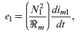
where, using Equation (7.11), the quantity within the brackets in the equation above is the magnetizing inductance of winding 1,
The analysis above is based on neglecting the leakage flux, assuming that the flux produced by a winding links all the other windings. In a simplified analysis, the leakage flux of a winding can be assumed to result in a leakage inductance, which can be added, along with the winding resistance, in series with the induced voltage ![]() in the winding in the equivalent circuit representation. A systematic description of the principle on which transformers operate is presented in [1].
in the winding in the equivalent circuit representation. A systematic description of the principle on which transformers operate is presented in [1].
REFERENCE
- 1. N. Mohan, T.M. Undeland, and W.P. Robbins, Power Electronics: Converters, Applications and Design, 3rd Edition (New York: John Wiley & Sons, 2003).
PROBLEMS
Inductors
The magnetic core in Problems 7.1 through 7.5 has the following properties: the core area ![]() , the magnetic path length of
, the magnetic path length of ![]() , and the relative permeability of the material is
, and the relative permeability of the material is ![]() .
.
- 7.1 Calculate the reluctance
 of this core.
 - 7.2 Calculate the reluctance of an air gap of length
 if it is introduced in the core of Problem 7.1.
 - 7.3 A coil with
 turns is wound on a core with an air gap described in Problem 7.2. Calculate the inductance of this coil.
 - 7.4 If the flux density in the core in Problem 7.3 is not to exceed
 , what is the maximum current that can be allowed to flow through this inductor coil?
 - 7.5 At the maximum current calculated in Problem 7.4, calculate the energy stored in the magnetic core and the air gap, and compare the two.
Two-Winding Transformers
- 7.6 In Figure 7.7, assume that the transformer has only two windings: winding 1 and winding 2, with
 and the leakage inductances are to be neglected. Winding 1 is applied a voltage
  volts at a frequency of
  . The load at the second winding is a resistor
  . Assuming this to be an ideal transformer so that the magnetizing current is zero, calculate and plot
  . What would this plot look like if
  is defined to be coming out of the dotted terminal of winding 2.
 - 7.7 Repeat Problem 7.6, if the rms value of the magnetizing current is 1/5 of the RMS value of the winding-1 current in Problem 7.6.
Three-Winding Transformers
In Problems 7.8 through 7.13, the three-winding transformer with ![]() turns,
turns, ![]() turns, and
turns, and ![]() turns uses a magnetic core that has the following properties:
turns uses a magnetic core that has the following properties: ![]() , the magnetic path length of
, the magnetic path length of ![]() , and the relative permeability of the material
, and the relative permeability of the material ![]() . A square-wave voltage, of 30-V amplitude, alternating between
. A square-wave voltage, of 30-V amplitude, alternating between ![]() and
and ![]() , at a frequency of 100 kHz, is applied to winding 1. Ignore the leakage inductances and assume the flux waveform to be symmetric with the same positive and negative peak amplitudes.
, at a frequency of 100 kHz, is applied to winding 1. Ignore the leakage inductances and assume the flux waveform to be symmetric with the same positive and negative peak amplitudes.
- 7.8 Calculate and draw the magnetizing current waveform, along with the applied voltage waveform, and the waveforms of the voltages induced in windings 2 and 3, assuming them to be open.
- 7.9 Calculate the self-inductances of each winding in Problem 7.8.
- 7.10 Calculate the peak flux density in Problem 7.8.
- 7.11 A load resistance of
 is connected to winding 2, and winding 3 is open. Calculate and draw the currents in windings 1 and 2, along with the applied voltage waveform.
 - 7.12 Assuming that winding 1 is not applied a voltage, and windings 1 and 2 are open, what is the peak amplitude of the square-wave voltage at 100 kHz that can be applied to winding 3 of this transformer, if the peak flux density calculated in Problem 7.10 is not to be exceeded?
- 7.13 In Problem 7.8, what is the peak amplitude of the voltage that can be applied to winding 1 without exceeding the peak flux density calculated in Problem 7.10, if the frequency of the square wave voltage is 200 kHz? What is the peak value of the magnetizing current, as compared to the one at 100 kHz?