
Smart devices can be smart without using a computing device, but they are obviously limited in their functionality without having the computing power to drive the inputs and outputs of the device. As you have seen from our first experiments with circuits, without an MCU to drive them, they can perform some basic functions, and provide a certain level of interaction. Aside from using a preprogrammed sensor or device with some logic already built-in, the ability of a circuit without an MCU to be truly “smart” is obviously heavily stunted. There are many considerations as to which MCU to use for your own projects, and which features and drawbacks will influence the selection most will largely depend on the use case.
It is also difficult to talk about the functions of the MCU fully separate from the sensors themselves, so I have tried to make sure to address the basics of the MCU in this chapter as a means to build from the last where we talked about the sensors themselves. Understanding how your MCU works and the ways to interface to sensors with it will make your projects much easier to design and build than if you figure it all out on the fly!
Small-ish
A device that utilizes a microcontroller chip – This means the chip has all the things like the CPU, RAM, and ROM all in a single chip. Examples of this are the Arduino family and the ESP family you can see in Figure 8-2 (the latter of which you will use in the labs).
Devices that are built around a microprocessor chip – This means the chip only has the CPU functions on board and the remainder are handled by other chips on the system. The prime and most recognizable example of this is the Raspberry Pi – it has peripherals, ports, connections for I/O, and a full CPU and runs a full PC operating system. (See Figure 8-1.)
Devices that are built for a very specific function and may or may not even have either a microcontroller or a microprocessor – These are called an ASIC, which stands for Application Specific Integrated Circuit. An example of these is found in high-speed networking applications where network communications gear needs extremely high throughput and low latency.
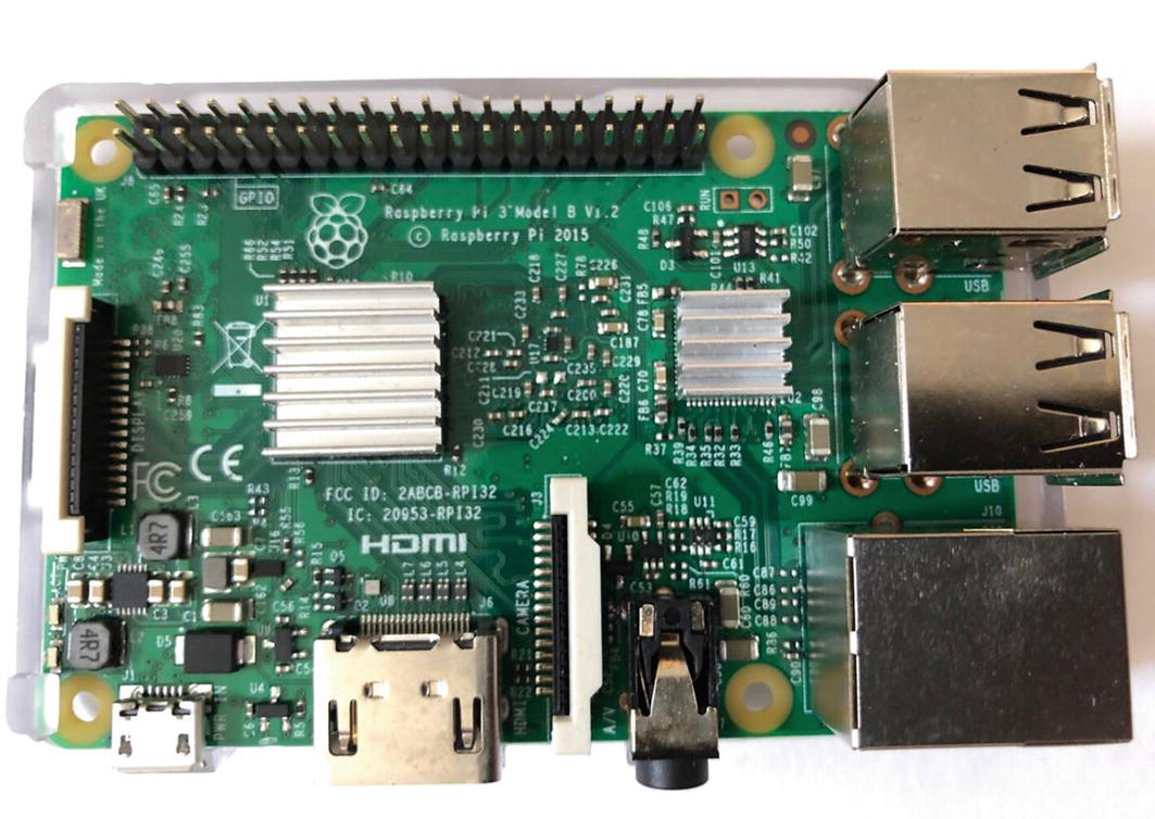
Raspberry Pi 3B

Node32S (left) and Arduino Nano (right)

An MCU with GPIO pins clearly visible

The Node32S MCU pinout diagram and the device

Digital only sensor – in this case a sound sensor

Analog sensor – also a sound sensor, but note the presence of an A0 pin

Basic Smart System Architecture

Diagram of the prototype smart system
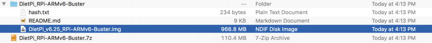
Filesystem view of the .iso file you need for the Raspberry Pi
Etcher selection screen
DietPi first boot screen
DietPi Software select screen
DietPi optimized software list

Confirm installation dialog
Install confirmation
Software install reporting screen
All done! Reboot confirmation
Raspberry Pi is ready to go with DietPi – great job!
Arduino IDE default sketch screen
Arduino Preferences screen
Board Manager menu

Install ESP32 board into IDE

ESP32 installed
This is a critical distinction between hobby-based solutions and something that is important for your own consideration as you embark on the smart device journey. A SoC with a microprocessor offers a lot: more power, more inputs and outputs, more expansion opportunity, more processing capability, and so on. With all of that capability comes some downsides that you can probably guess; they are bigger physically, they are more complex, and because of the layer of OS abstraction will have additional overhead. Probably the most impactful issue with a microprocessor SoC vs. the “all-in-one” types is that microprocessors are generally power hogs, requiring both high current draw at power on and a high sustained current draw as they run.
This is incredibly impactful to you in terms of your projects, because while a full microprocessor SoC may offer more accessibility in terms of tools and programming options, it may be that you cannot meet the needs of your project with the restrictions that it imposes. For example, while running a Raspberry Pi via a solar panel is possible, the size of the panel needed is probably impractical for most applications requiring long duration runtimes, as it would be quite large to generate the 5v needed. The battery likewise would need to be sufficiently large to store enough current to last through the night, and thus makes low-power Raspberry Pi use cases difficult (not impossible, just difficult).
Conversely the family of “all-in-one” SOCs like Arduino, Node, ESP8xxx, and the like are extremely power-light, often able to operate on a single coin battery for extended periods of time with good power management and intelligent coding. This comes with its own restrictions in that these devices are generally limited in what they can do and how expandable they are. There are always ways to expand them, and add in peripherals and expansions, but right out of the box, they might be limiting for your particular project. The other big pro for the “all-in-one” SOC is that with some exceptions, they are SMALL and super lightweight. The standard ESPxxx-based NodeMCU, for example, is only 49 x 24.5 mm and weighs about as much as a couple of coins. Packed into that space is a 32-bit processor, built-in Wi-Fi, a solid amount of GPIO pin options, and enough memory to store even the most complex applications. All of that and it retails for about $12 as of this writing, depending on which version you get.
That last bit is the real catalyst for the explosion of all of the types of SOCs – if you can get a fully functional one for less than $10 in bulk, why wouldn’t you put one in everything you make? That cost is for the fully assembled MCU as well; the parts to make one are incredibly inexpensive in volume; fractions of a cent in many cases. Having a low-cost MCU that is easily reprogrammed (no more UV lights!) and can run a variety of external sensor and power management functions means that suddenly the ability to control devices is not just limited to industrial applications anymore. If I can slap an MCU in my projects and get better interfacing and controls out of them, why wouldn’t I want to improve the UX? Thus, we come full circle to the whole point of this book. I have devices now that I can embed in practically anything and can easily manage and reprogram over the Wi-Fi that is all over my home and workshop.
All of this power also means when you are designing your smart system, an important consideration is balancing what you are collecting with each individual device. Too many sensors and load on a device may be a bad thing, and when you consider the entirety of the smart system (sensors, collectors, a processing gateway, and the display and action layer), you may really only need one or two sensors for each device. This also allows you to run much lighter code and makes for simpler management in terms of updates, break/fix (parts do wear out or get wet and stop working sometimes), and general maintenance of the system because you can simply swap one relatively inexpensive unit for another, and the system as a whole keeps functioning.
The Magic of GPIO and the Humble Pin
General-purpose input/output, or simply GPIO (pronounced by reading the letters gee-pee-eye-oh), is the single most important capability that an MCU offers the user. There are no MCUs in the mass market that do not have some form of GPIO that you as the designer and programmer control, as they would be too inflexible to support most smart devices. The standard means for these GPIO connections to be made is through a conductive metal rod that is generally soldered in place into one of the corresponding holes on the MCU. Sometimes you will get an MCU that does not have this done already and it will come with the rods to solder yourself in the form of what is called a “header” which is just a group of some number of the metal rods connected with plastic and ready to solder in place. Once they are, they become the conduit for the GPIO and are most commonly referred to as a “pin.” You can see a picture of a soldered pin on an ESP8266 MCU in Figure 8-3.
The unassuming pin is the cornerstone of all smart devices, and the ability to tell that pin exactly how to behave (as an input or an output) is the feature that allows us to bridge the divide between software and hardware, combining them into the smart device. GPIO capability is also one of the most important factors in how you choose your MCU, as it determines the total amount of devices you can interface with (sensors and outputs) and will have a very strong correlation with power draw and overall capability.
Fundamentally the common MCU has at its core three types of “pin” or connections to external devices. The two most obvious are the Power and Ground pins which we will use for completing circuits and connecting devices that need continuous power. The third is the true GPIO which can be any number of things depending on both the MCU itself some are defined by the MCU’s internal programming and wiring, and the rest of which are up to you the programmer to define. Figure 8-4 shows a common MCU pinout - that is the map of the pins and their functions - (this is an ESP32-based MCU) with its pins defined and labelled.
As you can see in Figure 8-4, the majority of this MCU’s GPIO are reserved for the user to decide on what to do with them – essentially everything labeled GPIOXX is yours to do what you want with. You will also notice that there are multiple labels on most of the pins as well, which indicates that they have an alternate function. Alternate functions allow pins to use multiple communications methods without having to dedicate pins, and thus physical space, to them - this is commonly used for things like I2C/SPI connections for example. This fundamentally reduces your overall pin count in a way, but the alternate functions are also generally reserved for communications protocols that enable multiple devices to be communicated with on the same pin. We will cover other communication means later in the chapter. For now we are going to focus on the basic function of the GPIO pins and their use as either input or output.
A0 or D0
Analog or digital is the basic question of the GPIO pin and something that you must consider when you choose your sensors. You will notice that some of the pins have a second label of ADCxx next to the GPIOxx in Figure 8-4. This indicates that the pin can be used in either analog or digital mode. At the most basic level this is a question of the data type the pin will relay to the MCU and is driven by the type of device connected to the pin itself. This is critically important when you start programming your software for your smart device as it will determine how you have to interpret the signals coming to or going out from the MCU.
An important analog and digital consideration also comes into play in terms of choosing the MCU platform you will build on. Why is this decision so important? Well, in the case of the Raspberry Pi, there are no native analog pins available, only digital. So, if you want to read analog data using a Raspberry Pi, and you likely will at some point, you are going to need to use additional components like Analog to Digital Converters (ADIC), to achieve your desired results. The other side of the Raspberry Pi is that, as a full computer, the Pi is uniquely suited to play the role of hub or gateway system in your smart system. It is capable of running things like Node-RED for data collection and processing, databases for storing data, full web servers for display, and a variety of other nice tools and functions for making a truly smart system on a small scale. As you go through the build lab in Chapter 10, you will build out a simple but full smart system that uses the Raspberry Pi as the hub.
Digital IO
Digital is the easiest to discuss because it is the simplest functional input/output model for using a GPIO interface. Digital I/O is like a switch; it is either on or off and there is nothing in between. You will see this commonly referred to as “high” and “low” which refers to the voltage of the pin in question being set to either its maximum available voltage (generally 3.3v for most MCUs, although there are exceptions – the Arduino Uno GPIO pins run at 5v) or no voltage at all. In the case of the pin being used as an output, setting the pin high and low generally signals a device on the other end of that pin to start and stop. It is also extremely handy for switching on and off LEDs for things like warnings and diagnostics. Along with the knowledge you have from the previous chapters of wiring an LED to a 3v power source, you can figure out quite easily how to wire that simple circuit up. Figure 8-5 shows a sensor that is digital only.
For an input device, the digital signal generally indicates that the state-change the device is designed to detect has occurred. We discussed this in greater detail in the previous chapter about sensors, but an example would be if this sound sensor detects a sound above a threshold. If you look closely at the picture, you will see a blue box with a grey-white “x” in it. That is a potentiometer (a type of resistor that can be adjusted) and it sets the value at which the sensor will “trigger.” Once that level of sound is reached, the internal logic of the sensor actually turns on its output pin to “high” and thus if your MCU is listening on that pin for that condition, you would be able to register in the code that a sound above the threshold has occurred. Digital signals are basic but are also very common and useful for smart devices since a lot of the functions of smart devices are real-time responses, and identifying an off/on type signal is much faster programmatically than reading in data and computing a result. However, it has very low fidelity, meaning that yes, I know a sound occurred, but I have no real idea of what level it occurred at other than “louder than what I set the threshold to.” If you need to know what level the sound is actually occurring at, that’s what an analog signal is for.
Analog
Like a digital sensor, an analog sensor also uses a change in voltage to indicate a change in condition. Unlike a digital signal, however, there is much more granularity, and interpretation of the signal is required to understand the output. Generally, the analog signal is a percentage of the maximum voltage, divided into slices. Those slices can be from 0 to 255, 0 to 1023, or whatever the sensor/device is programmed for and is generally published in the usage guidance for the sensor itself. What this means in practical terms is that an analog pin can send and receive fractions of the total voltage to the MCU, which in turn can allow for more fine-grained control over the attached device. Also, analog sensors are generally outputting readings all the time (with some exceptions for sensors that require a start/stop signal), which means that in order to collect those readings you might need to check the readings from the sensor a lot to get the level of fidelity you want. Figure 8-6 shows an example of an analog capable sensor.
I have purposely chosen two sensors that do the same basic function – sensing sound. In this case, the analog sensor would potentially offer a much higher level of fidelity to my application, as the presence of an analog sensor indicates that it could output more data. In this case, spoiler alert, it does, allowing me to get a sense of the actual sound level as a fraction of the maximum level (in this case a value somewhere between 0 and 1023 slices of the voltage). This could allow additional functionality in my software, at the cost of additional computation for me to do in code. This is an important consideration for your own devices. If you just need to know that something is or isn’t, then programmatically speaking a digital “yes or no” is oftentimes enough to accomplish the purpose.
As an input source to your MCU, this is used for sensors that are detecting the range of a condition. Light sensors, moisture sensors, humidity sensors, and many others use the returned voltage as a means of reflecting the amount of something detected. Generally (but not always), the higher the voltage, the more of whatever the sensor detects is detected. It falls on you to utilize the sensor documentation to determine what the value means, and to provide the associated logic in the software to interpret the voltage result.
The Software of Smart
As you saw in the first chapter of the book, the history of the computing and hardware required for building smart devices was a fractious one, with many companies competing to develop and bring to market all the hardware that drives these smart devices. The software that supports them was, as you can imagine, equally fractured, and it is this fractured landscape that leads us to having so many tools and languages for building smart devices. In some cases, this is limited by the hardware platform itself, as is common with Arduino-style MCUs that default to a C/C++ based application. It is possible to modify this behavior with other tools and libraries that let you build with another language entirely such as Python. In yet other instances, the platform will let you natively build in whatever language you desire provided there are hardware interface libraries available, as is the case with the Raspberry Pi.
In the larger smart system architecture – the place where a collection of smart devices work together to form a smart system – there are many places where one type of device is better suited than another, and this will often influence your choice of device/language/platform as you meet the needs of the system itself. A prime example of this is where real-time collection of sensor data is required – examples would be things like self-driving cars and robotics type situations where you need to sense and respond immediately. In such a scenario, the minimal configuration of the Arduino or ESPx family might be a better choice for collecting this sensor data. This is because it is possible for the sensor data collection to be blocked by the microprocessor-based architecture of the Raspberry Pi. If the hardware is busy with OS processes, the sensor data collection can be delayed. Granted, this delay could be very, very small, well under a second, but in a scenario like a self-driving car that kind of gap could be disastrous. In that scenario, the real-time nature of the Arduino would be a much better choice than the interrupt driven nature of the Raspberry Pi. It is possible to get the Raspberry Pi closer to real time through extensive tweaking and changes to the OS and services, but it may not be worth the effort when you can get that effect with a different MCU “out of the box.”
Fortunately, even when you must mix and match devices, you will also have the means to communicate between them with a universal language, which we will come back to. For now, our focus is on getting your devices running and accessible so you can start building your smart device systems.
A Brief Word on Tools
- 1.
An Integrated Development Environment, or IDE
- 2.
A place to store your code
- 3.
A way to get that code on to the device in question
You do not explicitly need an IDE to write code, but it is much easier.
There are many tools for storing code like GitHub, Bitbucket, Pastebin, and others, but you can store it on your local computer as well. I will use GitHub in the labs for some of its more convenient features.
The way you get code to the device depends on the device, and your personal preferences!
Notepad, VIM, VI, Nano, anything you can type lines of text in will work to write code. An IDE makes writing code easier, not possible. IDEs have features like syntax highlighting and inline debugging that tells you if you forgot a “:” or a “!” instead of having to debug it after the fact. They have libraries of different language packs that make writing any language more visually simple by formatting the code in the expected way with proper indents and syntax. They also include simple “nice to haves” like spell check and auto-complete. While you do not NEED an IDE to write code, I would highly recommend you have one if for no other reason than to make life easier on yourself!
There are many IDEs out there that you can use for building your smart application, and all of them offer tools and add-ons that make smart device code in particular more accessible and approachable, with new ones added almost continually. It is this rapid pace of change that makes a timely listing of all the parts and pieces you should include a difficult challenge in a printed form. Instead I am going to focus more on the tooling itself, and the pros and cons of using each one as it relates to a particular platform. It can actually be more difficult to develop against a certain platform if you start off with an IDE that is not well suited to it, and so making this choice up front is worth some thought before you go banging away, only to find that it doesn’t have the right libraries you need.
While I will stop short of a full “pros and cons” section here, I will say that my personal preference at the time of this writing at least is for either the “native Arduino IDE” or Visual Studio Code (VSCode) from Microsoft. Both are solid IDEs in their own right, and both will give you the basics without any issues, but it is important to note that with the Arduino IDE, you can write code to execute on other platforms (like an RPi), but you cannot use the IDE to load the code to an RPi, for example.
For programming the Arduino compatible family of MCU, the Arduino IDE has far and away the most library support, a strong community, and is obviously compatible with the MCU. For developing code, for any part of the smart ecosystem, I believe VSCode is a superior choice due to its native multi-language support, extensive add-on support, and general “developer friendly” presentation. Neither of these will be a bad option, and as I said before, an IDE only makes things easier. You do not need one to get going!
One quick side note on the Arduino and compatibles like the NodeMCU/ESP8266 based family of MCUs. Even if you do not use the Arduino IDE for writing your code, you will have to use it, or the command line tooling, for the flashing process. The way you must flash the Arduino compatible presents a downside, not of the Arduino IDE itself, but of the Arduino compatible in general. Because the board is generally programmed for the first time over a USB connection, you will need a computer that supports this. I know you are likely saying that all computers have USB, but not all USB devices are created equal and I can tell you that, at the time of this writing, it is impossible to flash an ESPxxxx-based MCU with a new MacBook Pro using UCB C ports. This is because of the way Apple has chosen to implement their drivers in newer versions of OSx, and a failure of compatibility with the Arduino drivers required to flash this particular device. I have no doubt this will change at some point, and I managed to get it to work exactly once in many hours of trying, but as soon as I unplugged the MCU, it stopped working and never worked again, even with a complete rebuild of my Mac from scratch. I have not experienced this issue with a Windows machine (in fact it was trivially easy to get an older Windows laptop to flash the same MCU reliably and repeatedly). This may have changed by the time this goes to press, but the caution remains that you should always verify you can connect to your hardware!
Regarding some sort of Internet-based code repository? This is the only hard and fast “statement of fact” I will make in recommending something to you - you should absolutely use something to store your code on that is not your local machine. Having your code stored in an external repository that persists if you change laptops, nuke your machine, forget to backup, spill diet Mountain Dew on your key board, and so on is one of those safety nets that you should absolutely have in place. Most of these repository systems are free, spectacularly easy to use, and you should do so. If you do not have an account for one, you should literally put this book down and sign up now. I will wait here until you get back. I have used GitHub myself in both Chapters 9 and 10 for the labs, as I am most familiar with it, but I am not in any way associated with GitHub, other than as a user. I can also tell you it has saved me multiple times already in a number of situations from “didn’t I write a loop that did that already?” to “oh heck, there goes my hard drive.”
Smart System Basics
With a basic understanding of what is needed to develop your code, let’s turn now to what constitutes a smart system. I discussed in the first part of the book that any smart system is fundamentally just sensors collecting data and sending it to a central repository. The basic architecture of all smart systems is fundamentally built on that exact idea: collect data and send it somewhere to see what’s going on. Easy right? Of course, as we all know, the “devil is in the details” and it is the specifics of your scenario that makes getting the right pieces in place a challenge. You wouldn’t really have much use for a motion sensor if you are monitoring the quality of the soil in your garden or probably care too much about light levels if you are always monitoring something in a closed pipe. The situation enforces obvious choices, but there are many others you will need to consider which we will discuss as we progress further through the book.
For now, let’s accept that at this phase, the first prototype, we are focused on one thing; a smart device that collects data and relays it to a central location. We can see the very basic architecture of this system in Figure 8-7. Your smart device will use a messaging method to send data to a central system.
The thing that makes your smart system “fit for purpose” is the combination of the sensors you employ and the data they collect, combined with what you do with that data on the other end. A smart system that only collects data but performs no actions – alerts, analysis, responses – is not really smart so much as “kind of aware.” Intelligence in a system is measured by its ability to detect AND react, not just detect. What makes a smart farm, smart? It is the fact that the sensors and their data are applicable to providing a detailed view of the conditions that are most associated with good farming outcomes (yields, disease/pest controls, growth rates, quality, etc.) and that the data they collect is used to take specific actions to maintain the best conditions for those outcomes. Turning on a sprinkler for dry soil is the most basic and, frankly, the most obvious and illustrative example of this type of outcome-focused system.
In order to build a smart system that provides comprehensive outcomes for the given environment being monitored, it will take a lot of trial and error, research, and just some basic good luck to find the right combination of data points and measures to make things match up to the optimal outcome. It is worth considering at this phase, before you begin the task of building this system, what is your outcome? My example of this is my own garden, where I began simply wanting to know if the soil was too dry for my plants, and I wound up building a complete smart garden. As my system got smarter (and I learned more about what it could do), I expanded my outcome to include new things that were previously not part of my initial design.
Smart systems grow and adapt as technology, uses, people, and capabilities evolve. It is important, as you will see in the discussion later in the book, to always keep this in mind as you start building out your devices. Your expectations and desires for the capabilities of the device will evolve and you can allow for this evolution in your design as you go. In our basic example though, our outcome is clear: dry soil = dead plants. We are going to ensure that scenario does not happen so that our outcome is plants that are alive! Over the rest of this chapter and the build labs that follow, you are going to build out this simple but effective smart system that will illustrate the concepts of all that you have learned up to now.
Let’s Get Ready to Rumble!
In order to build a complete smart system, you need to understand the basic architecture of the system, and what part does what. You are going to be building to a pretty standard DIY smart system model, using Arduino-based devices for collecting data from sensors at the source, and then sending that data to a Raspberry Pi acting as the processing hub for that data. You will be using application code for the Arduino, written in C++, and Node-RED as the processing engine on the Raspberry Pi. You will also use MQTT which is a standards-based messaging protocol that allows devices of different types to communicate with basic messaging. I will be introducing you to several concepts all at once during the build, and there will be gaps in what can be fully covered in the realm of this guidance – Node-RED could be an entire book by itself. Just keep in mind that it will all lead up to you putting some of the previous hardware knowledge and the following software knowledge into a system that allows you to collect data from sensors, send it somewhere using messaging, and collect and display it with a processing system. Figure 8-8 shows the exact architecture you will build out in the build lab.
A quick note – the “central hub” of the Raspberry Pi can also run on your own computer or laptop. Node-RED and Mosquitto (the MQTT server) can very easily run on a Windows or Mac system, so if you do not have a Raspberry Pi available, that’s alright, and you can just install the software onto your local machine as well.
The first step to getting your smart system running is to get your MCUs ready to receive code and perform their functions. I have purposely chosen to use a combination of functionalities, software, and language in the construction phase of this to create both simple devices and a functional smart system. I have provided code libraries that will run as is (via GitHub links provided with the labs in Chapters 9 and 10), if you are using the same devices that I specified in Chapter 2 for building up the workbench to complete the lab section later. Because there are MANY varieties of MCU, it would be impossible to account for every possible means and method of connecting to them and preparing them in a single chapter (or book for that matter!). Instead, I will focus on the same two types of devices (Arduino compatible using an ESP32 made by NodeMCU and the Raspberry Pi) as I have in both Chapters 9 and 10’s labs, and give the guidance that for others the instructions provided may also work, but you should of course refer to the documentation that is specific for your device.
Through this process, you will also see the differences in the two platforms come to life as you prep them for functionality. The Raspberry Pi, as a full computer, is significantly more complex to prepare, requiring things like a keyboard and monitor. The Arduino and compatibles are really more of a matter of “plug it into a USB port and you’re ready,” because the prep applies to getting your computer ready to load code into the device. Because of the contrast, I have not put the instructions “inline,” opting instead to have a separate path if you will for each device type.
Raspberry Pi Prep
Getting your Raspberry Pi ready to go is about doing a lot of stuff on the Raspberry Pi itself and very little on your own computer (as opposed to the Arduino which is pretty much the opposite). I will be walking you through using a very “lightweight” RPi operating system called DietPi, that allows you to do the basic things you want and customize as you grow your smart system out. You do not have to use DietPi, as any of the other operating systems available like Raspbian will work fine as well. If your Raspberry Pi was pre-configured you can use that OS so long as it supports Python and Node-RED.
The SD card that came with your Pi kit (if you ordered the kit online) or some other SD card.
A piece of software on your computer to write SD card images (I recommend something like SD Clone or Balena Etcher – both are really easy and simple to use and can be found with a quick Google search). You can also use the terminal to do this, but having the software is just nicer as it gives you progress and status.
You will need to download the latest DietPi image to your computer to write to the SD card; go to https://dietpi.com/ for the download.
You will need an HDMI cable, a TV or monitor, and a USB keyboard to complete the setup; it is possible to perform a “headless” setup with DietPi, but it has been my experience that this rarely works smoothly, and so it is safe to just assume you will need to plug it in and connect to it directly, and the instructions will assume this.
Wireless network credentials (also you may want the Raspberry Pi to have a fixed IP – this isn’t required, but it will make things easier over time since you will connect to it a lot!).
Once you have those things assembled, you can proceed through the setup steps here and get your Pi ready to go with the OS and Node-Red.
Download the DietPi image from dietpi.com.
Expand the downloaded zip file into a directory and locate the .iso file seen here in Figure 8-9.
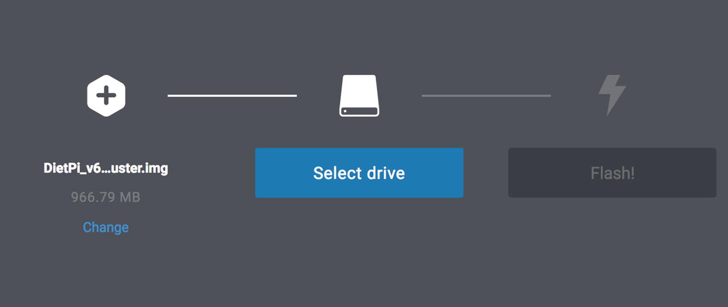
Launch Etcher, and choose the image you downloaded, and the SD card from your Raspberry Pi kit as the target, and then simply click “flash” as you see in Figure 8-10.
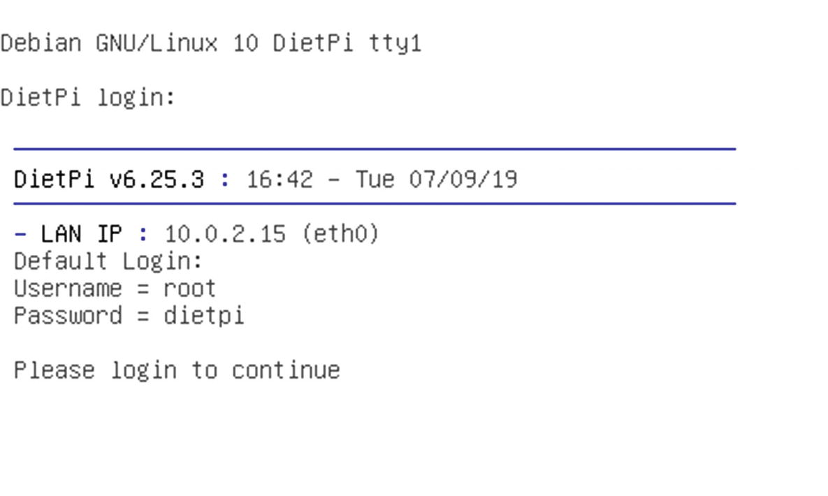
The process of writing to the SD can take some time, but usually not more than 5 or 10 minutes. Once completed, you can place the SD into the Raspberry Pi, plug it in the keyboard and HDMI, and then the power, and the system will boot up to the screen you see in Figure 8-11.
Node-RED
Mosquitto MQTT server
Also, at this point, feel free to install pretty much whatever else you might want, like a desktop or other tools; as the Pi is VERY flexible, you can use it for many things beyond the scope of this book, and I greatly encourage you to experiment! To install the basics for the lab, follow the steps given here (please note that there may be changes to the process with new versions of the OS – there are new versions released frequently and these steps might be impacted!):
- 1)
In the Software screen you should choose the “Software Optimized” option with the down-arrow key – confirm the selection by pressing “Enter.”
- 2)
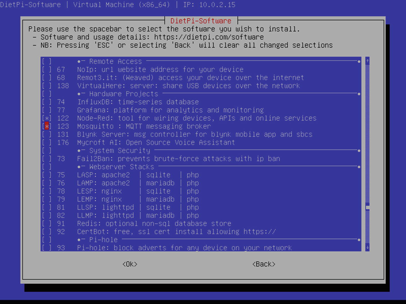
This will bring you to the list of optimized software. There is A LOT of them, which is why I usually recommend DietPi to people; the community support is amazing and there is so much that is “ready to go” for you to use. From this list, choose anything you want, but make sure to check the box by clicking the spacebar next to Node-Red and Mosquitto (numbers 122 and 123 and toward the bottom of the list in the Hardware Projects section) as you see here in Figure 8-13 and also find and click the box next to number 69 – Rpi.GPIO as you will need it for the lab (it is not shown in the picture but is higher up in the selection list).
- 3)
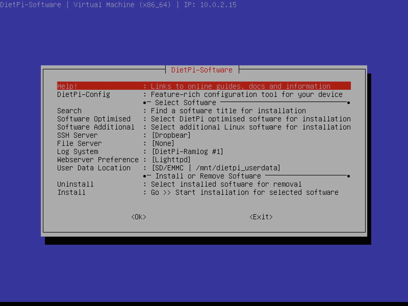
Pressing “Enter” will take you back to the initial software screen. From here just arrow down to “Install” to continue by pressing “Enter” as you see in Figure 8-14.
- 4)
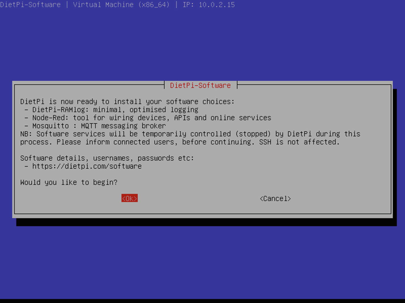
The software confirmation dialog box you see in Figure 8-15 will appear and ask if you are good with the selections. Arrow over to “OK” and then press “Enter” to start the install.
- 5)
The software will install (this can take a bit depending on your Internet connection and what you selected, but generally just takes a moment) and you will see the install progress on the screen.
- 6)
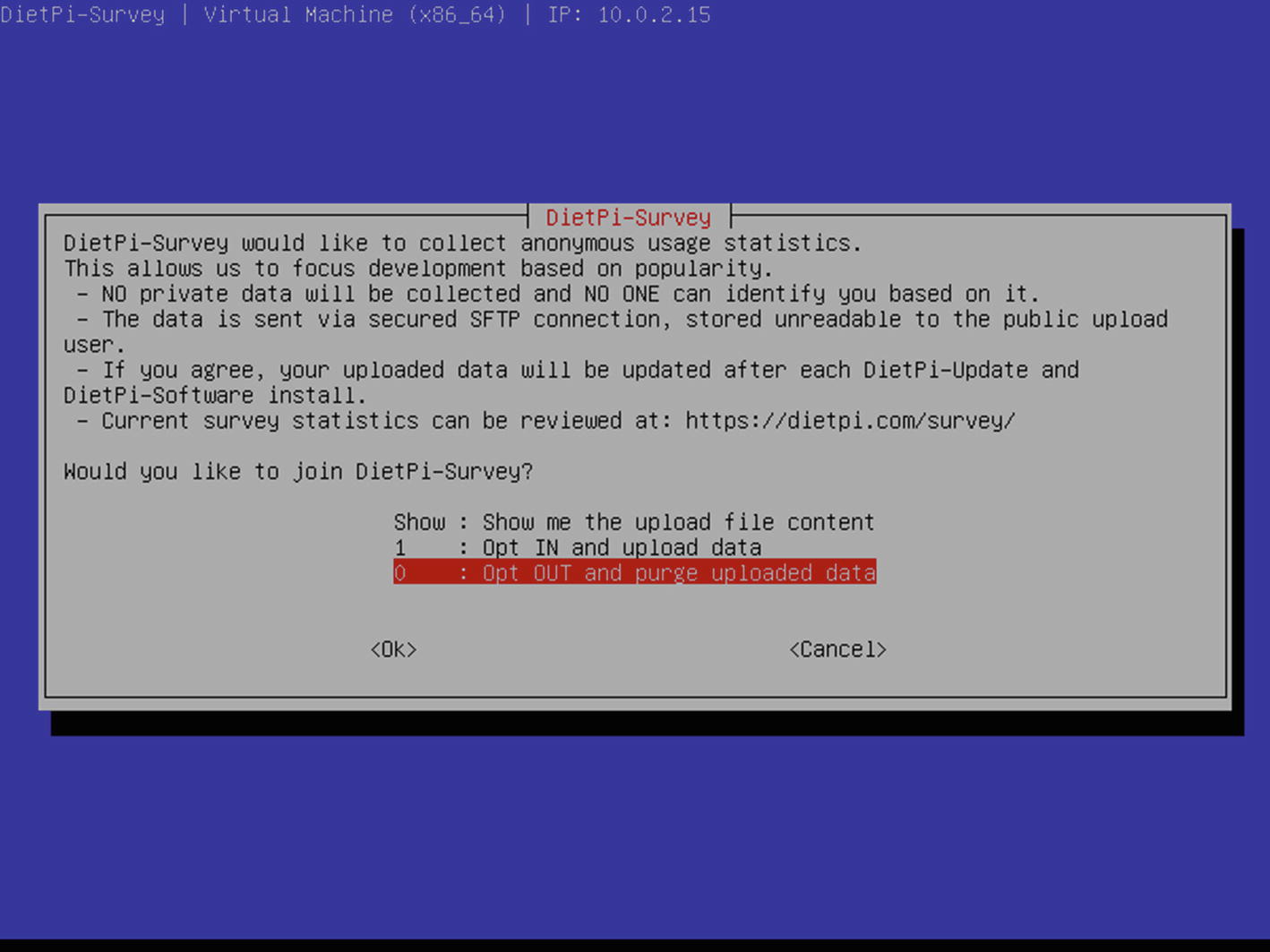
You will get one more confirmation as seen in Figure 8-16, which is the “data collection” option. DietPi uses this to see what bits of software people are using and where to ensure their support, so I recommend sharing it, but that is a personal choice of course! Arrow to your option and press “Enter” to continue.
- 7)
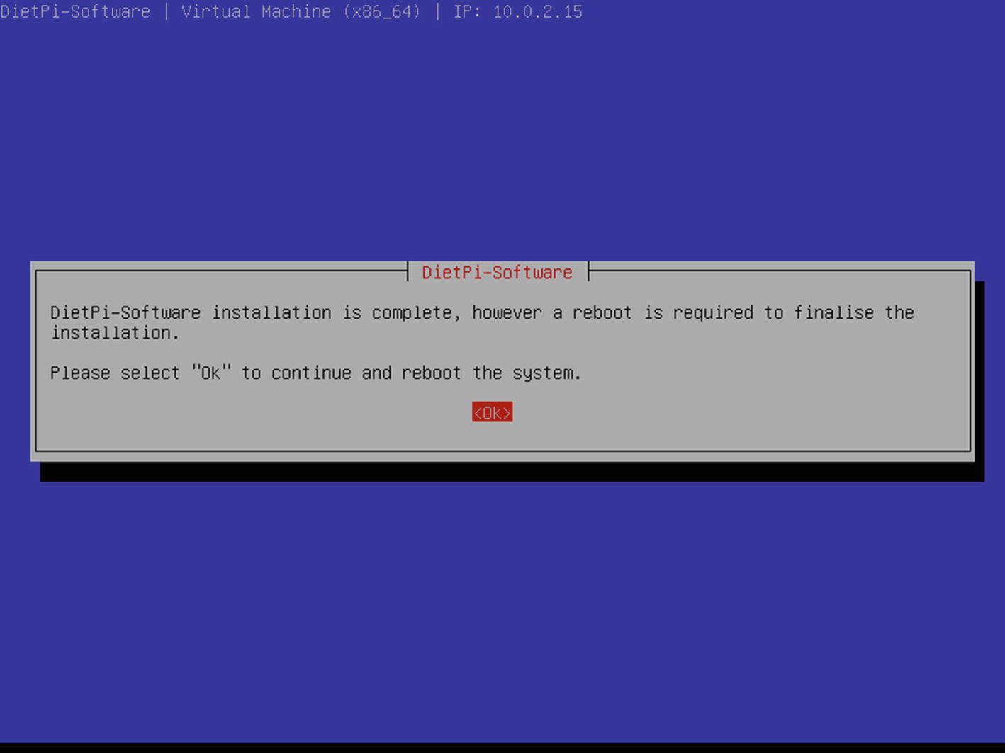
The system software will complete and prompt you to reboot as you see in Figure 8-17 – just press “Enter” to reboot and your system to complete the install.
- 8)
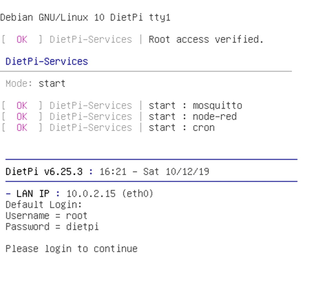
When the reboot ends, you will come back up to the screen you see in Figure 8-18, which means your system is now ready for the lab! You will come back and configure the software as you go through the smart system build lab.
From here you can proceed to configuring the ESP32 for the lab and then you will be ready to get started on the various builds in the next chapters.
Arduino Prep
Unlike the Raspberry Pi, the Arduino and compatible systems are pretty much “as is” out of the box. Getting ready to use them is much more about the preparation of your computer than of the MCU (which is directly the opposite of the Raspberry Pi). In order to use the Arduino and compatibles like the NodeMCU, you will need the Arduino IDE, and probably most importantly a USB data cable. This is a really important note for the Arduino compatibles – MOST USB cables that you would get to say charge or power a compatible are NOT data cables and you will spend a super long time figuring that out. If you do nothing else to make your life easier, order the USB data cable I listed in Chapter 2 and have a few of them around. Your sanity will appreciate it!
Download the latest Arduino IDE.
Install the right “boards” from the board manager (boards are what the IDE calls the various type of compatible devices you can program).
Install any additional libraries.
Code your code.
Verify it and then load it to the device.
Repeat until you have it the way you want!
- 1)
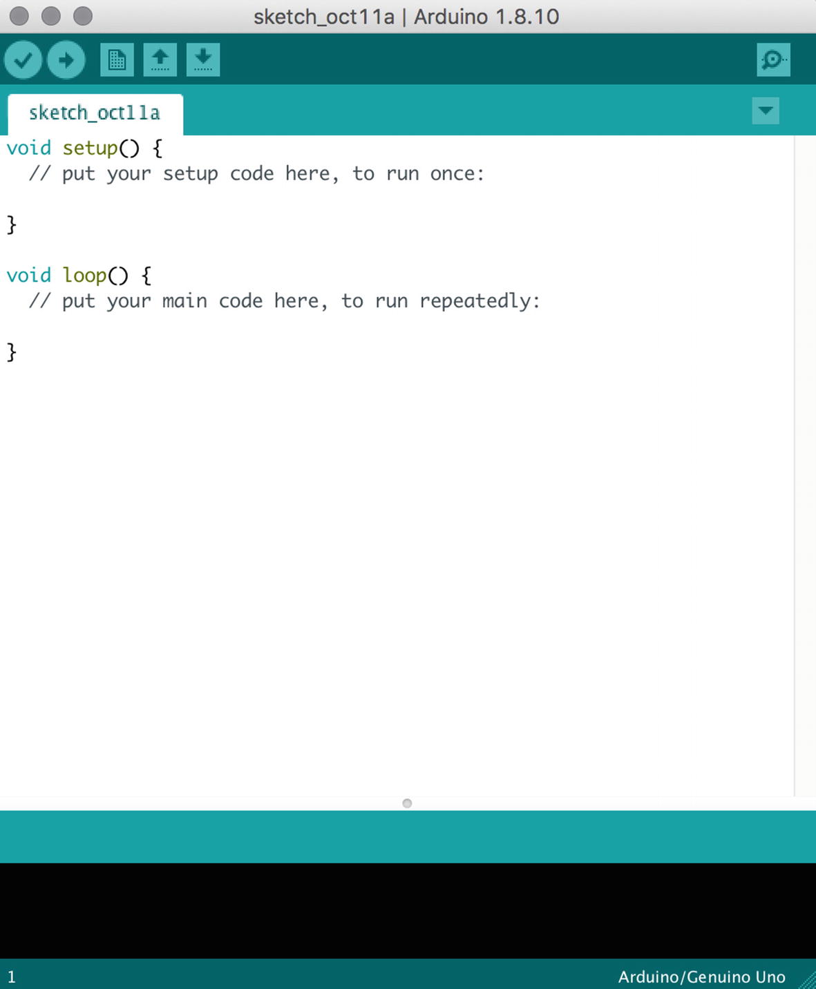
First, you’ll need to download and install the Arduino IDE. The latest version can be found here: https://www.arduino.cc/. Whatever the latest version is will work fine, as they have done a very good job of maintaining the compatibility and structure of the IDE to look and feel the same from version to version. When you are done, you should wind up with a screen that looks like Figure 8-19.
- 2)
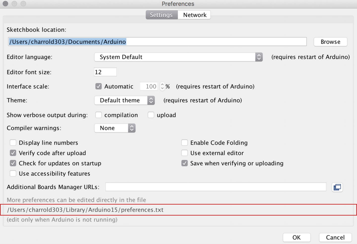
Next you need to install the type of MCU you are working with. Luckily the Arduino IDE makes this relatively easy by building the board manager right into the IDE. You will need the exact link that is shown below the image in 8-20 (you can find it online for copy and paste ease):
https://raw.githubusercontent.com/espressif/arduino-esp32/gh-pages/package_esp32_index.json
Copy and paste it into something handy, as you will need it to tell the board manager to load additional board interfaces. You do that by choosing Arduino ➤ Preferences from the application menu. You will see the screen in Figure 8-20.
You want to put the URL from above into that field in this screen and click OK.
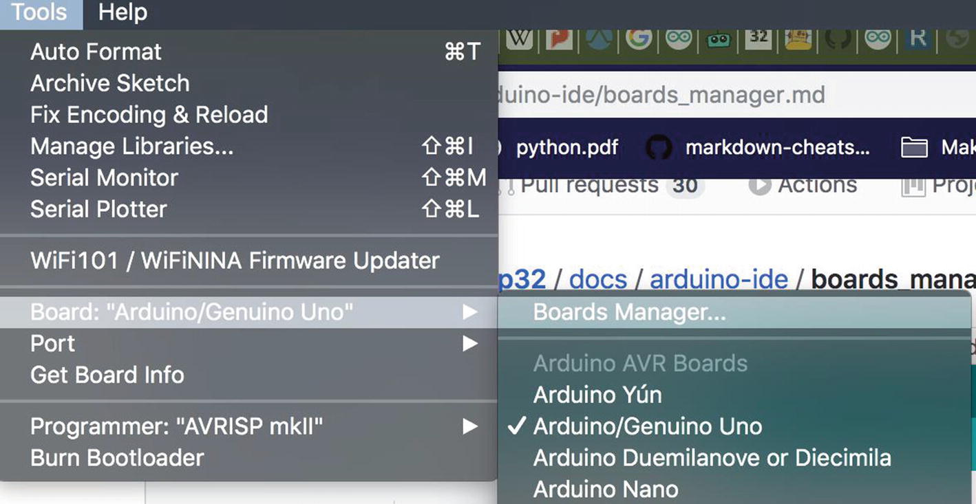
- 3)
Now back in the main screen, choose Tools ➤ Board “Arduino/Genuino Uno” ➤ Boards Manager… from the menu as seen in Figure 8-21.
- 4)
In the Board Manager, type “esp” in the search field and select “Install” when you see it in the list as in Figure 8-22.
This will trigger the board tools and drivers to download to the local cache. When it is done, you will see a screen like Figure 8-23.
Now the ESP32 is installed and you can program it with the IDE.
Congratulations, your ESP32 is ready to be programmed and you can move on to the build labs in Chapters 9 and 10 with confidence!
A Word on Code
I feel I would be a bit remiss if I did not take a moment and look at the actual code itself. This book is very much focused on hardware, because as I have told you throughout, the hardware presents the bigger challenge. There are endless resources online for hardware and software, but hardware is physical, can go badly wrong, and can cause injury when mishandled. It is just scarier. Software, on the other hand, you copy and paste from an example online and, provided you put the wires in the right place, it just works. Worst case it throws an error, but that’s minor, and doesn’t result in a painful shock or worse. I hope throughout I have demystified the hardware process and got you to the point where you feel more comfortable with it.
I have purposely stayed away from the nuts and bolts of writing working code then, because there are infinite resources for it out there. I have also provided you with code via GitHub that you can use in the build labs in the next two chapters that will, if followed precisely, “just work.” This is a little unfair to anyone who is coming to this without a coding background as the code is a part of the smart device as much as the hardware. Thus, I think it only fair that I give you at least a little overview of what is happening under the hood.
In the build lab, you will be doing the “Hello World” of hardware and blinking an LED. I want to take a moment and show you the code that you will use for the lab for both platforms and dissect it out a bit so you can see the code and I can show you what it does. Interestingly, in the case of the Arduino, the required library to interface with the GPIO pins is actually installed “under the hood” so you do not need an include statement for it. This will change with other sensors later, but unlike the GPIO library for Python on the RPi, you get access to the pins by default in the Arduino world.
C++ code sample for blinking an LED
Digital reads do what you think, they listen to the specified PIN for a signal to come in. This will get used in the build for listening to the sensors and reading the value they are sending. Same with analogRead, although that is a more sensitive measure of the level of the voltage of the pin as we discussed earlier. analogWrite then would allow you to pass the voltage level you want to write at to the pin. There is a nifty variance of the “Hello World” that actually dims and brightens an LED using analogWrite and sending gradually increasing and decreasing voltages.
lines. Delay is the equivalent to telling the MCU to just wait for xxx milliseconds. This is really, really useful for allowing things to happen or not, and in this case, with no delay between “off” and “on” you would not even see the LED blink at all. It would appear to be on for about half a second or less and then shut off. Side note, I tried it and you see a very faint flutter of the light because it is turning on and off very quickly.
Python code sample for blinking an LED
The Raspberry Pi has multiple GPIO modes that support changing the way the GPIO pins are numbered, and here we are telling the software to address the GPIO via the “BCM” mode. This means that the GPIO pin numbers are not the literal pin number on the header, but what the Broadcom Chip that controls them defines them as. There is no right or wrong for this setting, it is just something to be aware of and understand because it will make a difference in your code on the pin address you specify.
The second line is actually something I would not recommend in all but the simplest of projects like this one, because it tells the application to ignore any warnings from the GPIO subsystem. Generally, this is bad, but in this case, there is very little to be impacted by it. The last one is telling the GPIO that the pin we want to use (pina which equals 4) is an OUTput pin and thus will send voltage out, not read it in.
The Print command is just like the output to the serial console from the C++ command that gives you some debug information. The GPIO commands are the equivalent of the digitalWrite commands in C++ turning on and off the LED by changing the mode of the pin from HIGH to LOW. The last bit is the same as the C++ delay() function and here it tells the code to pause for the duration of the interval defined in the code.
That’s the main things to remember for the Python side – forgetting to set the pin mode is a common mistake I still make frequently!
Summary
Whew, that was a lot! I hope that I have not crammed too much into a short space here, but there is just SO MUCH when it comes to all the interconnected disciplines in smart devices. As I said, this book is more about the hardware and so I have tried to stay true to that, but a smart device just isn’t without software. There are so many great resources for writing good code and the tools and functions of it that I hope you will forgive me for not going deep into that part of the smart device world. Maybe another book for that someday, but for now I think it is high time you got to building! The two chapters for the Build lab has three total projects: Hello World (aka blinky lights), a simple sound sensor reader, and a full (but simple) smart system with both sensors and outputs. I do hope you enjoy building them as much as I did!