
In our last chapter we explored some of the basics of electrical engineering and the fundamental concepts that form the basis of circuits and electronic components. As you grow your skills in smart device construction, you will inevitably come to a point where the limits of basic resistors and circuit design no longer allow you to progress. This happens fairly quickly after your first builds, and in this chapter, we will explore more advanced circuit topics, and some of the most commonly used components for advanced circuit designs – transistors, diodes, and capacitors – as well as discuss some basics around other control mechanisms you are likely to encounter. All of this groundwork leads up to the next section where we introduce the idea of a computer “brain” to control these devices.
The Transistor
The transistor is everywhere in modern electronics, and it is safe to say that without it we would not have the modern computing era. Transistors make up a huge part of the central processing unit (or CPU) of computers, as well as providing the processing power in MCUs. This is what allows them to process and calculate instructions from code; by controlling the flow of electricity they create the 1s and 0s which make up the language of computing. This simple device is effectively an electrically controlled switch, but unlike a relay, which we will cover later, they offer a couple of significant advantages in terms of both size and power needs.
There are MANY types of transistors, and you will undoubtedly come across them in your own research, but the types we will focus on here fall into two categories: BJT (N-P-N or P-N-P) and MOSFET. The reason for focusing on these two is that, aside from needing a whole book to cover all the types in detail, these two types are the most common in smart devices. The BJT is used commonly as an electric switch, and the MOSFET is often employed in things like motor controllers for robotics.
BJT Transistors (N-P-N or P-N-P)
This type of transistor is an excellent means of switching on a current using a minimal amount of power. Effectively, this type of transistor has two inputs for the circuit you are controlling, and one output. Unfortunately for first-timers, using a transistor can be a little confusing at first. That is because transistors operate on the flow of electrons, but circuits operate on what is called the “conventional flow,” which, as we saw in the last chapter, is from + to – on our battery. When you first come to BJT transistors you will find this diagram (Figure 5-2) everywhere.
The easiest way to think about the usage of a transistor of this type in your design is to follow the arrow. The arrow in the diagram points in the direction of conventional current flow, meaning that most likely you want your transistor to be an NPN type. Thus, the collector side of the transistor is where the current you want to turn on and off comes into the transistor, the emitter side is where it will exit, and the third connection is the control signal.
The reason for this is the switching mechanism of the transistor is controlled by a relative charge method that compares the emitter voltage to the base voltage. In an NPN, the way you “turn on” the switch is to apply a current to the base, thus raising that value above the value of the emitter voltage and allowing the current to begin to flow. In a PNP transistor, you would “turn it on” by actually turning off the current to the base and allowing the current to flow. To be clear, BOTH WORK FINE to control the current, but generally we think of turning on and off in terms of “having current” and “not having current” and so this distinction is as much for your own circuit designing sanity as anything. Certainly, in a simple circuit, where you are using the transistor in place of a switch, this makes the most sense.
There are instances where having a transistor in a “current-on” state might make sense in a circuit though. For example, you might want current to flow through the transistor if something is NOT happening. In the case of software-controlled devices, you could be holding up a signal for some length of time via your code or waiting for a condition to stop occurring via the output from a sensor. In both cases, having a “switch” that stops electrical current while current is applied to the base might be advantageous as a means of controlling other functions of the circuit. Having the flexibility of both types of transistor will give you better control in designing complex circuits. As you can see in Figure 5-3, the transistor has three areas inside it, the collector side, the control (also called the base), and the emitter.
In an NPN transistor, applying power to the base means the current can “jump” over to the emitter side. In a PNP, you must turn off the flow to the base to allow the current to cross through the base material.
Some huge advantages of this model is that you can switch a very high voltage current with a very low voltage signal – for example, in the smart device world, if you wanted to control a 5v current with the 3v pins that are common on most MCU devices, a transistor will allow that, whereas a relay may not, due to its higher power needs. This could be used to perform a variety of actions like powering on and off an array of sensors all at once instead of with individual pins. This would give you the net effect of having control over their power consumption but only require the use of a single general-purpose input/output (GPIO) pin on the MCU, a critical concern when you are dealing with a finite amount of usable IO pins on your MCU. (GPIO is covered in detail later in the book.)
Another powerful function of the transistor is its ability to amplify the voltage passing through it. While this is not common in smart devices per se, it is hugely powerful for things like sound and video, and you will find transistors in every major piece of audio and visual gear you have around.

A mix of transistors

Two types of BJT transistors – NPN on the left and PNP on the right

Internal of a BJT transistor

FET cirucuit diagram
FET diagram
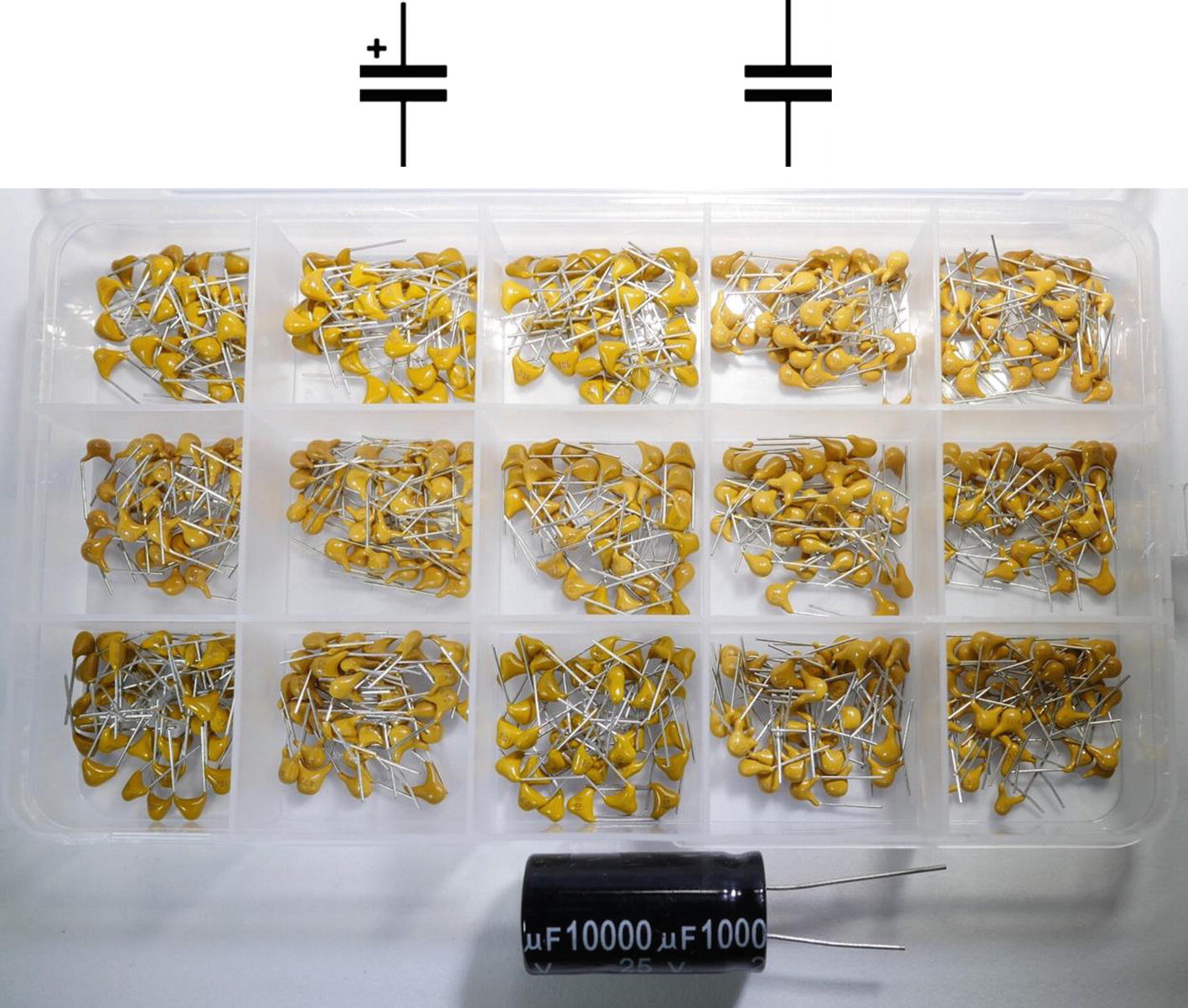
Capacitors and their symbols (top left – polarized capacitor; top right – basic symbol; under – various capacitor types)
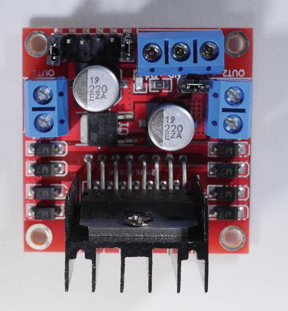
MOSFET motor controller L298N with two big round capacitors on it (labelled with a 220 EZA)
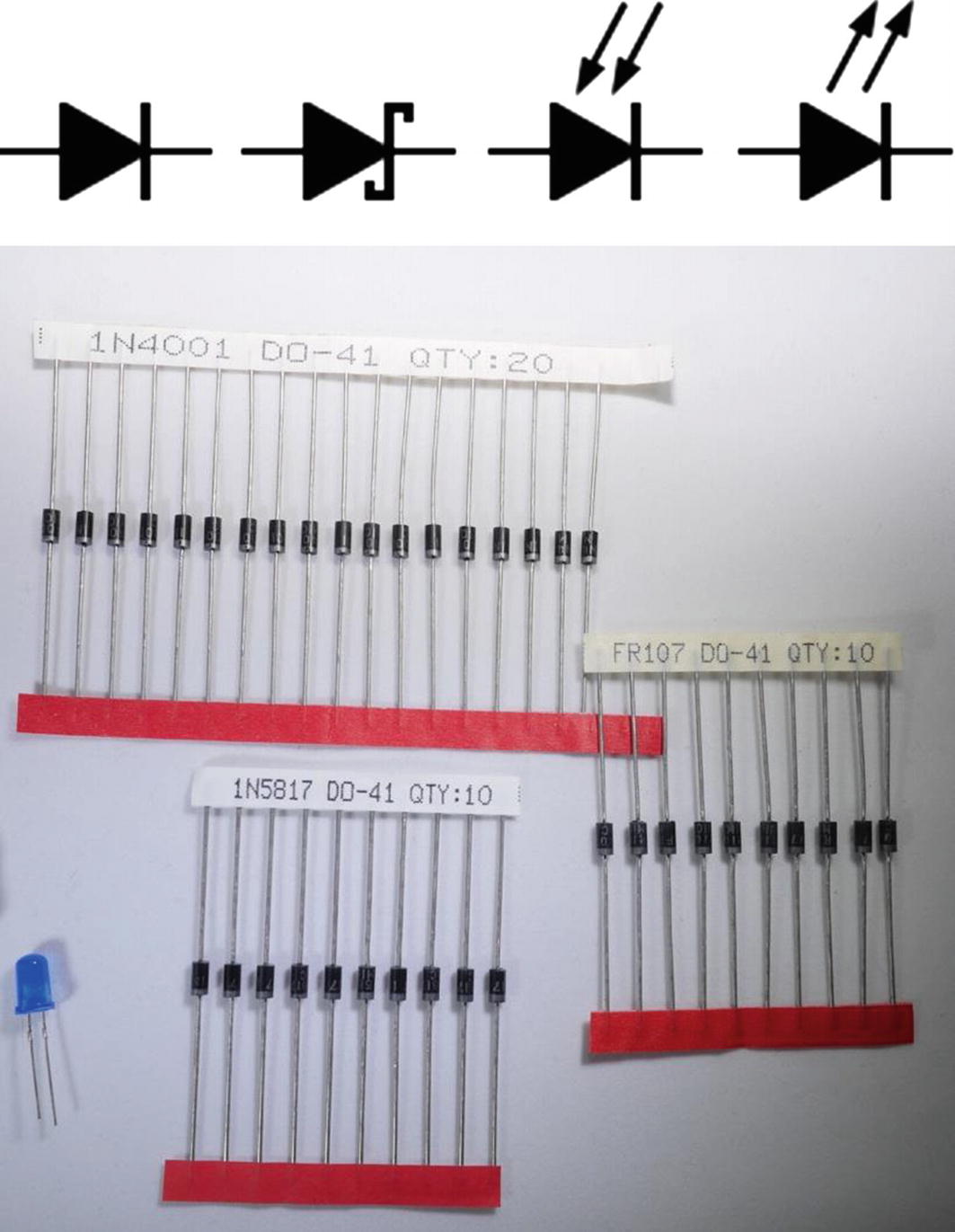
Diodes and their wiring diagram symbols (top left – standard diode; second from left – Schottky diode; second from right – photodiode; far right – light emitting diode (LED); bottom – various diodes)

Diode directionality

AND and OR gates
Examples of relays on a pre-made circuit board
FET Transistor
The FET style of transistor (of which the MOSFET is arguably the most common) refers to the way the current is passed through the transistor through what is called the Field Effect Transmission method. This method relies on the creation of an electromagnetic field to control the flow of power. (Incidentally, the MOS refers to the material the MOSFET is made from in this case, Metal Oxide Semiconductor.) The big advantage of FET over BJT is that they are generally smoother in operation (the current flow is better) and they require very low voltage to let A LOT of current flow through. This is what makes them ideal as motor controllers since most robotics motors are anywhere from 9 to 24 volts; a voltage which would immediately fry any common MCU device. With a MOSFET motor controller, you can turn the flow of current to the motor on and off using the available 3v pins on the MCU without danger to the device. Figure 5-4 shows the wiring for a MOSFET transistor. If it looks familiar, that’s because it is the same as the BJT; the difference is all in the functionality and composition of the transistor itself.
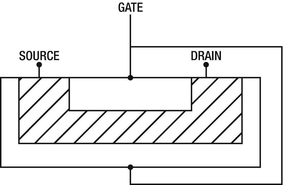
Like the BJT transistor, there are three connections to the MOSFET style transistor: the source, gate, and drain (Figure 5-5). Just like in the BJT, these control the current flow. The source is exactly what it sounds like, the source of current you want to control. The drain is the destination (like the emitter in the BJT) for the current flow. The gate is the on/off switch and is what produces the magnetic field to allow the current to flow through the FET.
As you can see here, the internal mechanism of the FET is different from the BJT, and it is this difference that allows it to function much more smoothly, and to be miniaturized much more tightly than a traditional BJT transistor – a fact which obviously makes them valuable in smart devices! Transistors rely on impedance to control the flow of electricity, which is like hyper-resistance because it is a combination of the resistance we discussed before and the reaction of different conductive materials that allows or prevents electrical flow. The gate layer in the FET is what controls the flow of the current, and because this electromagnetic bridge has a very high impedance when the gate is closed, it allows the FET to control very large loads with very small voltage applied to the gate. For example, there are surface mount MOSFET transistors capable of controlling voltages in excess of 120v that are about the size of the head of a match. That is a lot of control in a very small package!
I would be remiss at this point not to note that there are a wide variety of other transistor types that you are likely to come across, but I have chosen to focus on these two types for the simple reason that one or more of them is often included with the various “starter kits” that are widely available on the Internet for people getting started with sensors and circuits. There is a myriad of information on the Internet for using other styles and applications of transistor tech for your own projects, but the FET and BJT styles presented here will be a very common piece in your workbench.
The Capacitor
Perhaps second only to the transistor in common use for smart devices, the capacitor has nonetheless a hugely important part to play in circuit design when you move into advanced circuits. The capacitor uses a similar principle to the battery, in that it can store electricity. Unlike the battery, it can accept and expend that electrical energy very quickly (nearly instantly in some types of capacitors). This is incredibly useful in situations where you have electrical noise or perhaps you are looking at using battery power for a project. A capacitor can provide a “smoothing” effect to the power supply that is causing electrical “noise” or spikes and dips in currents, and in the case of batteries, having a correctly wired capacitor would allow your device to continue to function while the battery is being changed. Highly useful for things like wearables and other battery-specific devices. As shown in Figure 5-6, there are many types of capacitors as well, due to the need to have the right size for the load of current and discharge, as well as the function they are performing.
The measurement of the capacitor is not as simple as a battery, where an AA battery provides 1.5v, for example. The capacitor is measured in farads, and they are generally in fractions of a farad at that. A full farad (incidentally named for electrical pioneer and enemy of good cell phone signals, Michael Faraday) is an enormous amount of capacitance, and so most of the capacitors you would use are actually rated in fractions of a farad.
If we want to liken the capacitor to our plumbing example in our basic circuits, the capacitor would be akin to a water tower. It collects water from the system and stores it in the tower. Water continues to flow through, but “extra” water piles up in the tower. If we were to turn off the water flow, the water in the tower would still supply everything “downhill” – that is following the tower in the system – until it was empty, or the flow of water from the source started up again. The amount of water that the water tower can release and in what amount of time it can release it would be its capacitance.
τ = RC
Time Tau (τ) equals the product of the resistance and the capacitance.
Have an ASTRONOMICAL amount of resistance – for example, I used a 1M Ohm resistor and a 9v battery with a 100 nanofarad capacitor and I could just barely see the LED dim out in a pitch-black room. Of course, I could also only barely make out the LED since that much resistance meant VERY little current made it to the LED! So how long did my fade-out last?
τ = RC
τ = 1,000,000 ohms × 0.0000001 farads
τ = 0.1 seconds
So, for all of that crazy high resistance, I bought 1/10th of a second?! Not really all that amazing to watch.
Have a lot of capacitance in parallel – why parallel and not serial like a battery? Because capacitors in SERIES have a fractional relationship to capacitance, whereas those in parallel are equal to the SUM of the capacitance. So, if you take a bunch of reasonable capacitors, say something in the 100 μF range (100 micro farad), and maybe 10 of them?
τ = RC
τ = 460 ohms × (0.0001 × 10) farads
τ = 460 ohms × (0.001) farads
τ = 0.46 seconds
Well, that’s actually starting to approach reasonable – if you switched it up with some bigger capacitors, say 1000 μF, and had a few of those, now you could get to a reasonable delivery of power in an observable time.
Have a large amount of capacitance and reasonable resistance. 100 nanofarads is infinitesimally small in the grand scheme of things, and even 100 μF is pretty tiny. What happens if I go for a big gun and bust out a 0.01 farad (10,000 μF) capacitor and put my resistance at something much more reasonable (a 9v battery lighting a basic LED needs 460 Ohms)?
τ = RC
τ = 460 ohms × 0.01 farads
τ = 4.6 seconds!!
Well that’s much more reasonable! I can actually see it dim and go out in that amount of time.
Now, if you repeat this experiment in the build lab later, you will see that in fact there is light coming out of the diode for MUCH longer than 4.6 seconds; that is because the discharge of the capacitor is not a linear or instantaneous discharge. Over time, the amount of voltage the capacitor is outputting starts out at full power, but gradually decays, producing less current as the amount of time gets longer. That means that your Tau value is roughly the amount of time you have BEFORE this decay kicks in – for comparison’s sake, in the 0.01 farad example, I was actually trying to time it and I got as high as around 6 seconds (using the highly scientific “counting of 1-Mississippi” method) before I saw a noticeable decay in the amount of light from the LED.
In advanced circuit designs, you will see capacitors predominantly used where you want the flow of power to be smooth and even, or where you need a battery-like storage of energy in a shorter window of time (such as the battery powered device where you need it to stay alive long enough to change the battery). The Tau value then is the value you should consider in your design as the “safe time” before your power drops off. Also, WHAT gets powered is important here. In a smart device, very rarely would you want to power literally every part of the device in the event of a power loss. Much more likely you would want to design a circuit that provides power to the key part (like an MCU or memory for storing things) than to all the lights and sensors.
One additional common place capacitors are used that you will recognize is in camera flashes. The capacitor charges up from the camera battery, and when the flash is triggered, it dumps all that into the flash bulb to create a powerful light. You will also see them used anywhere there needs to be a strong signal like this to “kick off” an action, as they can power up to a much higher level than the input current over time. (Think about the noise an old-school flash makes charging up? That’s the current rushing in to fill the capacitor.) They are often found in smart device applications in conjunction with motor wiring to provide a smooth start-up current as otherwise you would have a kind of “jolting” (no pun intended) inrush of current that could be unstable and cause odd performance of the motor (or damage even). You can see a couple of capacitors in Figure 5-7 on the wiring for this common MOSFET motor control circuit, and you will see them again in the circuit lab in the next chapter.
Diodes
Diodes are a very simple and common electrical component that gives two basic functions to the circuit designer – control of the direction of flow and protection from current going where it should not. Like all types of electrical components, there are many different types and sizes of diode (as you can see in Figure 5-8), but they all have the same basic function; they are the one-way valve of electrical circuits.
As with so many electronic components, there are A LOT of options here. To keep the focus of the book on things you are likely to use and need in your own designs, I am focusing on just the more common diodes and their functions in this section. The basic diode you will get in most kits or diode collections is a silicon-based PN diode. These are great for basic circuits and can handle quite high voltages without bleeding current back through the diode and self-destructing. Yes, this is a thing. If the current trying to come back through the diode is too high, it can cause the diode to fail, and unfortunately part of that failure is allowing the current through the wrong direction. However, good circuit design and knowing your voltages and currents will mitigate this.
The Schottky style diode is made up slightly differently than the PN diode, much the way that the BJT and MOSFET are different but perform a similar function. The Schottky diode is more efficient when it comes to switching on and off when current is applied, resulting in much faster “on/off” state switching, which can be very useful in situations where high speed and precision are required. However, they have a much lower failure point than their PN brethren and will fail sooner, so care must be taken in ensuring that they are used in situations where they are not likely to be exposed to a lot of reverse current.
You might come across the need for diodes when you are building your circuits and connecting different wiring routes together into a single path. Having a diode in the path would ensure that no current goes the “wrong way” and comes back to a device that isn’t expecting it. Practically speaking, there are not a lot of circumstances where you will have to have a diode to protect the flow of a circuit, generally electricity only wants to go one way. However, the diode has some really interesting other properties that you might want to exploit in a circuit. One of these is the ability to create light as the flow of electricity passes through the conducting material, and thus the Light Emitting Diode (you know it as an LED) is born! That’s right, one of the most important components in any making project is a diode, which also means that by using one, you are ensuring that electricity flows only one way in that circuit!
Diodes, as a one-way entity, need to be installed in the correct direction! Larger diodes are usually labelled pretty clearly as to which end is the positive and which is the negative end of the diode. Figure 5-9 shows both an LED and a regular silicon diode.
The circuit diagram for a diode also shows the direction it is expected to be installed, with the positive arrow pointing to the negative bar as you can see in Figure 5-8. With smaller silicon-based diodes, the “bar” that is printed on the diode casing is the negative end and should be placed “facing away” from the source of your circuit’s power. For LEDs – a diode that emits light – the long “leg” of the LED is the anode, and the shorter leg is the cathode. If for some reasons the “legs” are the same length, you can also feel the LED for a flat spot on one side of the plastic lamp. That flat spot faces toward the cathode, or negative, side and so should “face away” from your voltage source.
One other very important consideration in your designs for using diodes of any type is the concept of voltage drops. Any electrical component in a circuit has the potential to consume some of the flow of that circuit. This is totally normal and expected, but as you are going through your first circuits and building things out, it can lead to some unexpected results if you do not understand the reason why. In the case of the diode, there is a concept that you need to be aware of called Forward Voltage Drop. This is the amount of voltage the diode will “consume” as the current passes through it. Fortunately, this isn’t an arcane art or something you need to divine! Diodes are generally clearly labelled with their operating voltages and forward voltage drop as relates to the current in the circuit. Luckily most modern diodes also “consume” very little current (something in the ranges of 200 or 300 mV even in circuits with loads as high as 1 amp). To put this in perspective, the max load from an ESP8266 based chip via one of its GPIO pins (not a dedicated 5v pin, but the regular GPIO defined pins) is 3v, so even with a diode in sequence, you lose VERY little of your overall voltage from the circuit. LEDs are an exception to this in that they consume more of the voltage for creating light than a regular silicon diode, but the loss of voltage through the LED is usually made up for by supplying more voltage, or isolating LEDs in your design.
One last thing to note about the diode in general, and LEDs in particular. Later in the lab section you will see one of the troubleshooting tips is to “turn the LED around.” I have been making things with LEDs for many years now, and I still plug them in backwards. Remember that an LED is first and foremost a diode, and what does a diode do? Allows flow in one direction only! If you “plug it in backwards” with the anode and cathode legs reversed, no electricity will flow. It also means that you can simply switch that around, and voila, flow is established.
Lastly there are a couple of very interesting things you can do with diodes to create advanced circuits. These revolve around creating “gates” for electrical connections. In the case of an electrical circuit, a “gate” is a place where some set of conditions has to be satisfied to allow the flow of electricity to proceed. You will generally see them notated as the type of gate they are, and a diode or diodes can be used to create two very simple gates, the AND and the OR gate. Just like the type of gate they are, these gates match two criteria together to make a logical path of electricity flow. AND gates require the conditions to ALL be satisfied. OR gates require ANY of them to be satisfied. Here in Figure 5-10 is an illustration that will help.
In your own project, you may want to have multiple circuits feeding into a single receiver. By using diodes to create an OR gate, you could allow the condition at the receiver to be TRUE, meaning that electricity is flowing, if ANY of the diodes are outputting current. This could be useful in detecting if one or the other of a sensor has triggered a finding on the same pin on your MCU, for example. It would also allow you to trigger an LED from two different places – like contact sensors, for example, on a door and window on opposite sides of a room. This would light up the LED if either of the two sensors was activated separately from one another.
Conversely, you could also set up a circuit that is wired so that you need ALL of the sensors to be sending current. That would be an AND gate. In the diagram, the voltage source passes through a resistor that controls the flow of current to an output – maybe an LED in this case. If only one of the diodes is activated (let’s say that the door is open in our example, but not the window), the current that would flow to the output would be a fractional current and not enough to do anything with the output. If both diodes are activated though (the door and the window are both open) then the current would flow through the output at the full output of whatever is passing through the resistor.
The function of the diodes in these examples is not the logic itself since the wiring of the circuit determines that. It is to allow these circuits to be tied together without allowing electricity to “leak” into a place it is not expected.
Other Common Elements
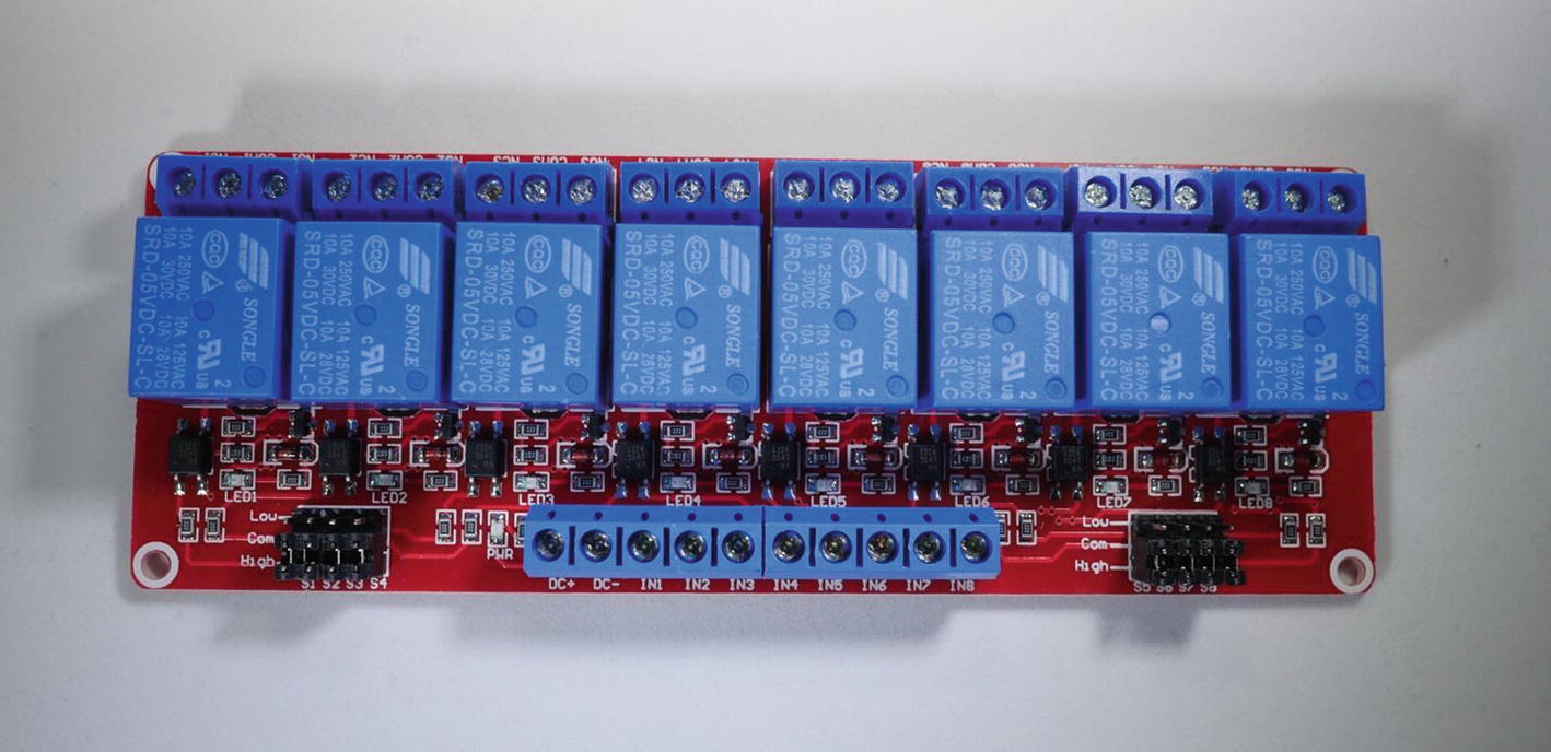
There are a few other common elements that didn’t really warrant the full section treatment but warrant some introduction as you will come across them commonly in many smart device projects. The first of these is the relay. This is like a transistor in that it allows turning the flow of current on and off. Unlike the transistor though, it is an electromechanical process (meaning it has moving physical pieces inside). This also means that it has different characteristics than a transistor in terms of operation. Primarily you will see relays employed in things like home automation where you want to control very large voltages (110/220) with your MCU devices. The main thing to know about the relay is that the switch requires a minimum voltage to activate. This means that you need to account for the activation voltage in your design since your MCU may not put out enough voltage to actually trigger the switch!
There are many types of relays, but generally you will find them pre-assembled in something like the picture in Figure 5-11: one or many relays pre-mounted to a circuit board, and ready for wiring with the screw terminals provided.
Generally, the relay operates by introducing a voltage differential, much like the transistor, but with a MUCH higher required load. Relays are commonly used to control things like lights or lamps in a smart home application (at 110v) or motors and other larger electronic systems (usually 12 or 24v). This allows an MCU operating at 3 or 5v to activate the relay, although you may need to combine some current outputs using AND circuits to get enough voltage to the relay to activate it. Fundamentally though, relays provide a quick and easy way to get switched control to one or more devices from your MCU.
Headers are sets of pins that are pre-formed into neat packages and ready to mount on a circuit board. You will find there are as many headers as there are everything else, and you can trim and customize headers to your exact need as well. They are important in a circuit because it is not always possible to have everything on the same board, or sometimes you need to marry two circuit boards together. Headers give you the flexibility to do just that, without the permanence of soldered connections. Headers are also a great way to build in some expandability to a circuit since you can have a header connected to power, ground, and data sources/inputs and attach a device to it later. You can also find pin headers used as gates, where if pins are connected then current flows to a new location and a new function is activated. You can see a few examples of headers in Figure 5-12.
Other connectors also deserve a mention here as you will often find the need to use things like network cables and USB in your circuits to extend your reach beyond the breadboard or circuit board. RJ-45 connections are an easy way to run wired sensor devices over long distances, for example, as they give you an easy way to connect structured network cable (category 6 is the current standard) to your circuit and pass the connections over great distances (50 feet or more) without huge voltage drop. USB ports are obvious power sources but can also provide output capability in more complex designs. Camera connections, display connections, audio ports, HDMI, you name it, all of them can be used in a smart device if you need that functionality.

Various sized headers

Types of connectors you might encounter (clockwise from top left – a fuse-block with a bladed connector, a Flat Flex Cable [in this case a Raspberry Pi camera cable], a USB C connector, a 5-pin header an RJ45 cable connector, a four-wire cable connector, a “crimp” connector (the little blue thing - the wires are crushed inside it by the connector) and a screw terminal)
Summary
I could continue on through so many exotic and amazing connectors, electrical components, and carry on down the rathole forever really. There are just so many possible ways to control and use electricity it is kind of overwhelming, but the topics and devices in these last two chapters are the ones you will FOR SURE use, even early on in your building of smart devices. The next step is to actually BUILD some of them! The build lab that follows is all about creating some functional and useful circuits that will do things, even without the use of the microcontroller. You can actually go quite a long way with just battery powered circuits and you will build some functional circuits in the lab that will show you the basics, help you get familiar with the concepts we’ve discussed, and give you a handy reference when you need it later.