
A picture is worth a thousand words, and from this common adage, the integrated computer-aided software engineering (CASE) tool was born.
CASE, or modeling tools, emerged in the 1980s and were promoted as the silver bullet for rapid development, claiming to increase productivity and yield higher quality software. Consequently, they became one of the mainstay technologies of the RAD paradigm.
This chapter covers the use of models and modeling tools in the software development process. The Unified Modeling Language (UML) for defining software models is introduced, and we cover the advantages models bring to the task of developing component-based applications. Specifically, we shall see how UML models:
Communicate the software architecture to members of the team
Help validate the design and assess the impact of requirements and design changes
Assist in the process of exploring and understanding the structure and dynamics of applications and components
The chapter also examines the benefits of using modeling tools for constructing and maintaining models and provides guidelines for selecting a suitable modeling tool. We also cover how making models the center of the development process can improve developer productivity, yield higher quality software, and reduce timeframes.
In the context of software engineering, a model is an abstract diagrammatic representation of the form, structure, and intent of a software application using a standard notation. Typically, this standard notation is the UML.
It is not mandatory to use the UML for defining a model. However, the UML has become firmly established as the de facto standard for software modeling since it was first formalized by the famous trio of Booch, Rumbaugh, and Jacobson, collectively known as the three amigos.
Models make it possible to describe the pertinent aspects of a system’s architecture clearly and accurately, and serve as a rich communication medium. Here are some of the things you can represent with a model:
Understanding and describing the problem domain
Software structure, organization, and constraints
Object and component collaboration
Information flow
System state
Database structure, organization, and constraints
Packaging and deployment of the application components
Models offer a mechanism for communicating the system design to all members of the project and help build a common understanding of the system. They also assist in the process of validating the ability of the design to meet the customer’s requirements.
Most people are familiar with models of one form or another. I’m not referring to software models but to the type more commonly built by children with a little help from a responsible adult, usually to prevent any serious damage with the modeling knife or to stop tiny fingers from becoming glued together.
Children build models because it is fun and educational. Moreover, they lack the skills and resources necessary build the real thing. My first such model was a reconstruction of a World War II Spitfire, constructed using a plastic modeling kit, a sharp knife, and some glue.
The finished model could be shown to school friends to explain how a real Spitfire worked. The model perfectly illustrated where the pilot sat, the location of the guns in the wings, and how the propeller spun and pulled the aircraft through the air.
When it comes to modeling software as opposed to toy aircraft, the same benefits apply. UML diagrams help construct low-cost models of the software and enable the communication of system design and behavior quickly, accurately, and succinctly.
By modeling the system requirements, an analyst can convey to the customer his or her understanding of the business functionality the application must exhibit. A carefully constructed software model highlights any areas of ambiguity, thereby allowing them to be addressed during the initial stages of the development process with input from the customer.
When modeling the design of the application, the same benefits apply. A low-cost model of the design provides an excellent mechanism for communicating all aspects of the design to both customers and colleagues. With the UML, ideas and possible design solutions can be sketched out on a whiteboard where they can be readily discussed and refined among the design team.
In this manner, the UML serves as a common vocabulary for the effective communication of solutions. Representing designs in this format is a significantly faster process than producing reams of written documentation and is less ambiguous.
The benefits of the UML as a common vocabulary that can span language and cultural barriers should not be understated. Given the business practice of moving development work offshore, software engineers are finding themselves in the position of having to work as part of virtual teams, where team members are geographically remote. In order for this project structure to work successfully, accurate communication of technical information between team members and a common understanding of the system is imperative.
Children and software engineers are not the only people who build models. The practice is commonplace in the engineering profession. Going back to the example of the model aircraft, real aircraft designers employ a similar technique as part of the design process and build a mockup of the final aircraft.
The aircraft designer’s model is made from a malleable material like clay and is built to prove the viability of a new plane’s design. By placing the clay model in a wind tunnel, metrics can be obtained as to how the real plane will perform once it leaves the drawing board. In this way, the designer can get an early indication of whether the design meets the specifications for the plane in terms of speed, stability, and load-bearing qualities.
Software models provide the same benefits. UML interaction diagrams enable the software engineer to determine if the various components that make up the design are capable of collaborating in order to execute each of the system’s use cases.
Design validation has two main benefits: it helps drive out risk, and it enables change on the project to be measured and controlled.
Models are inexpensive to build. By being able to test a model early in the development process, the risk of a design failing to meet a significant customer requirement is drastically reduced.
Finding shortcomings in the software architecture later rather than sooner can be an expensive and time-consuming business. Though refactoring tools for making sweeping changes to the code are of considerable value, time savings can be made if the number of refactorings an application must undergo are kept to a minimum.
Change is endemic to the software development process. A model is an effective mechanism for assessing the impact of any change on the design and hence the final system.
Like the clay models of the aircraft designer, software models are also malleable. We can update our model in light of the change and then revalidate the model. If it transpires that one of the use cases is no longer supported by the original design, then we can go back to the model and refine it further. Thus, the model can be used to experiment without the need to write lines and lines of code.
UML diagrams help capture both the static and dynamic structure of software architecture. Unfortunately, architecture defines a diverse range of system concerns, making it very difficult to represent even the simplest of systems with a single diagram.
Rather than trying to think of architecture as one giant picture, it is easier to break this picture into smaller chunks, or views. In his paper “The 4 + 1 View Model of Architecture” [Kruchten, 1995], Philippe Kruchten defined five concurrent interlocking views of architecture. Using this multiple view approach, each of the four views models a separate set of architectural concerns. Architects use the fifth view for the illustration and validation of the other views.
Since Philippe Kruchten’s paper first came out, the view names have undergone a few changes. Here are the generally accepted 4 + 1 views of architecture:
Logical view.
The logical view defines the structure and organization of the software in terms of packages, classes, subsystems, and layers.
Implementation view.
The perspective of this view focuses on the various files and components that constitute a deliverable release of the software. Unlike the logical view, this is a physical view of the makeup of the system.
Process view.
The process view describes the concurrency concerns of the system and models the interaction of runtime aspects such as tasks, processes, and threads.
The deployment view defines the different hardware nodes of the system and describes the location of software components within the runtime environment.
Use-case view.
This final view is a special view that helps shape the architecture and is taken from the perspective of the customer, analysts, and testers.
There are two wider perspectives of architecture: logical and physical. These two perspectives represent the view’s type. Logical views focus on software constructs such as packages and classes. Physical views model hardware nodes and files.
Table 5-1 depicts the types of each of the four views.
Table 5-1. Architectural View Types
View | Type |
|---|---|
Logical | Logical |
Implementation | Physical |
Process | Logical |
Deployment | Physical |
Architects can use the different UML diagrams to build up these concurrent views of the software architecture. The overall architectural picture is a mosaic of all the UML diagrams used to depict each of the various views.
We examine the main UML diagrams next, with respect to the 4 + 1 view model of architecture.
Building a model requires a suitable modeling material. For software models, this modeling material is the UML, which enables analysts, designers, and developers to describe the static and dynamic structure of all aspects of the system. The UML diagrams most commonly used in software development are
Use-case diagrams for defining the organization of a system’s use cases
Activity diagrams for representing process flow
Class diagrams to show the static structure of software
Interaction diagrams to show the dynamic structure of software
Component diagrams for defining the relationships between system components
Deployment diagrams for illustrating the physical configuration of software and hardware
Let’s examine these diagrams in more detail.
If you are employing use cases to drive the development approach, then a use-case diagram will form part of the analysis model of the functional requirements of the system. The use-case diagram provides a pictorial representation of the various relationships between the use cases and actors that make up the system. A member of the team wearing the analyst’s hat generally produces use-case diagrams in consultation with business representatives.
Note
Use cases are discussed in Chapter 3.
The notation of the use-case diagram is very simple and generally easily understood by nontechnical staff. This makes use-case diagrams an ideal mechanism for discussing system requirements with the customer. Figure 5-1 illustrates a basic use-case model.
The use-case diagram depicts the following elements:
Actors, represented as stick men
Use cases, shown as ellipses
The communication association between an actor and a use case, as defined by a solid line
The relationship between use cases, depicted by a dashed line with an arrow for indicating the direction of the relationship
The system responsible for executing a use case, identified as an enclosing rectangle
The use-case diagram in Figure 5-1 shows the three main actors of Customer, Shipping Clerk, and Warehouse Clerk. The Customer actor communicates with the Login, Register for Account, Search for Items, and Place Order use cases. Each use case resides in the Online Ordering system. A relationship is shown between the Login and Register for Account use cases.
note
Use-case diagrams might suggest that use cases are graphical rather than text-based, detailed requirements documents. You may find the use-case model is a nicety rather than an essential modeling element. UML diagrams are not a prerequisite for working effectively with use cases.
It is more important that the use cases themselves correctly detail the system requirements than that a use-case diagram exists. If you are running short on time, you may wish to ignore the initial use-case diagram and concentrate your efforts on accurately defining the content of each use case.
For the architect, a use-case model serves as the use-case view of the software architecture. This is the special fifth view of the architecture, and it defines the key system use cases as being architecturally significant.
These use cases are a subset of the total that make up the complete system and form the basis for ongoing modeling and prototyping efforts during the inception and construction phases. During later stages of the project, they offer a baseline against which system changes that impact the software architecture can be measured. These use cases are also known as primary use cases.
Care should be taken when selecting the primary use cases that shape the system’s architecture. Be sure to pick a diverse cross-section of use cases to model for the initial architecture rather than focus exclusively on one functional area. Avoid the obvious high-profile candidates that concentrate on screen inputs and outputs, and instead look to functionality that defines integration requirements, security concerns, exception handling, and batch processes. These all assist in addressing technical risk early in the project.
Activity diagrams are similar to flow charts and describe process flow, representing both conditional and parallel behavior. Consequently, activity diagrams model the system’s dynamic behavior. Figure 5-2 shows an activity diagram.
The notation of the activity diagram defines a process flow for a specific scenario:
Activities performed at each step of the process flow are shown as rounded rectangles
Transitions between activities are denoted using arrows
A fork, where a transition splits into two or more parallel activities, is shown as a black bar with one transition entering and several leaving
A join, where two or more parallel activities converge into a single activity, is shown as a black bar with several transitions entering and one leaving
The object, actor, or system responsible for a particular activity is represented by an enclosing rectangle known as a swim lane
Activity diagrams are applicable to all five architectural views. One of the most effective uses of the activity diagram is to include it within a use-case document to illustrate the use case’s different flows.
The class diagram is probably the most widely known UML notation and defines the static organization and structure of the software. Class diagrams receive the most attention from software engineers because they offer a convenient notation for conveying software structure. They are commonly used in the definition of the logical and process views.
Figure 5-3 depicts the basic notation of a class diagram and shows the classes involved in the system, modeling the relationships between classes of type Customer, Account, Corporate, Personal, Order, and Item:
Classes are shown as rectangles with the name of the class at the top of the rectangle
Attributes and operations are shown inside of the class element
Associations between classes are represented by solid lines
Adornments on associations further describe the relationships that exist between classes, such as generalization and aggregation
Role navigability is represented by arrows on association relationships
Associations with no arrowheads are bidirectional
Multiplicity is shown by numbers on the association
From the UML diagram, an association exists between the classes of Customer and Account. The multiplicity for the association specifies a Customer may have one or more instances of the Account class. The association between these two classes is unidirectional, meaning Account objects are visible to objects of type Customer, but not vice versa.
The empty diamond states that the relationship between the two classes is one of simple aggregation. A solid diamond denotes an association by composition, which links the lifetimes of the two objects in the relationship.
composition and aggregation
Composition and aggregation are both forms of containment whereby one object holds a reference to another object. The semantics of aggregation and composition relationships define how the lifetime of the contained object is managed.
With composition, the containing class is responsible for creating and removing the internal object. The contained object cannot exist after its parent has been removed.
In an aggregation relationship, the lifetime of the contained object is independent of the containing object, and so it is free to live a life of its own.
Looking at other parts of the diagram, we can see that classes Corporate and Personal are both specialized forms of Account, thanks to the generalization relationship depicted in the diagram.
tip
Class diagrams can describe the organization of a system’s design elements in fine detail. However, many architects find detailed class diagrams become cluttered and difficult to read. Consequently, basic class diagrams that describe the software at a high level are often more informative than those containing a highly detailed view.
The class diagram can also be used in a high-level form as a package diagram. Here, the package diagram shows the organization of the software into packages and defines the dependencies that exist between them.
Whereas class diagrams give a static view of the software, interaction diagrams are dynamic. Interactions diagrams are found in all five of the view models of architecture.
Interaction diagrams come in two types: sequence and collaboration. They both demonstrate the dynamics of the software system and illustrate how objects defined in the class diagram collaborate to execute each of the system’s use cases. In this way, interaction diagrams are a means of demonstrating that the model can meet all the business requirements detailed in each use case.
Sequence and collaboration diagrams model essentially the same information, but each has a slightly different emphasis.
Sequence diagrams are organized on time, with events occurring in chronological order as you progress down the page
Collaboration diagrams emphasize object organization and message flow
Models can be built using either or both types of interaction diagram, depending on preference. Most modeling tools automatically generate the alternate diagram type for you.
The sequence diagram in Figure 5-4 depicts the following information:
The object or actor who initiates the scenario is located at the left edge of the diagram
Objects are shown at the top of the diagram as rectangles
The lifetime of each object is represented by a vertical dotted line
Messages passed between objects are defined by solid arrows
The activation bar, a thin vertical rectangle drawn over the object’s lifetime, illustrates the duration of a message
The example is for a very simple scenario and models the passing of messages between objects for associating an order with a Customer account and adding items to the Order.
Sequence diagrams enjoy greater popularity than collaboration diagrams, but the choice of interaction diagram type is purely one of preference. For comparison, Figure 5-5 depicts the collaboration diagram equivalent of the sequence diagram represented in Figure 5-4.
Message flow in a collaboration diagram uses a different notation than that of the sequence diagram:
Associations between objects are shown with solid lines
Small arrows on the associations show the passing of messages
Message sequencing is defined by numbering each message
Be sure to define interaction diagrams for the primary use cases that form the use-case view of the architecture; otherwise, validation of the static model is not possible. The interaction diagram proves the objects in the system can collaborate to execute the flows specified in each architecturally significant use case. Furthermore, interaction diagrams help members of the project understand how objects in the system should interact.
Objects in a system have both state and behavior. Statechart diagrams map the different states of objects within the system and identify the actions that trigger an object’s change in state. Like interaction and activity diagrams, statechart diagrams model the dynamic aspects of the system and apply to all five views.
Figure 5-6 shows a UML statechart diagram.
The statechart diagram conveys the following information:
The different states of an object, shown as rounded rectangles
The actions resulting from a change in state, defined in the lower part of the state’s rectangle
Transitions between states, represented by arrows
The event that triggers a state transition, shown as text on the transition arrow
Figure 5-6 shows the basic states in sending out a customer invoice. The Preparing Invoice state is entered by the event account outstanding.
Within the Preparing Invoice state, the action of calculating the invoice is undertaken. On leaving the state, the action is to mail the invoice to the customer.
Statechart diagram are excellent for modeling any part of the system considered state-driven.
Component and deployment are two different diagram types that are often merged into a single diagram. They fall into the category of a physical diagram, showing the packaging and deployment structure of system components.
Component diagrams show static structure and are incorporated into the implementation view if created as a single diagram. Deployment diagrams also describe static structure and form part of the deployment view.
Figure 5-7 depicts a combined component and deployment diagram.
Architectural elements defined in the diagram shown in Figure 5-7 include:
Hardware nodes, represented by the rectangular boxes
Physical software components, shown by the rectangles with two large tabs on the left edge
The relationships between components, shown as dashed arrows
The communications protocol between hardware nodes—for example, TCP/IP
The diagram depicts the three server nodes of a multitier distributed architecture, with software components deployed to each tier. Communication between the tiers is over TCP/IP.
To recap, adopting modeling techniques as part of the development process gives very distinct advantages to the project:
Improves customer communication
Improves team communication
Reduces design risks
Measures and helps control requirement changes
These are all valid reasons for employing modeling techniques on the project. However, not all software development organizations use modeling for the betterment of the software but for other, less laudable reasons:
Internal quality procedures mandate the production of UML design artifacts for documentation purposes.
Having sought funding for a modeling tool, the project team feels honor-bound to justify the expenditure.
The customer has specified a model as a project deliverable.
Using only these reasons for adopting modeling on a project is a sure sign of the development team going through the motions of software modeling. Here, the application of modeling is construed as just another task on the project plan instead of as being central to the development process.
If development teams are not confident of the real reasons for using modeling methods, they risk engaging in cargo cult software development. In this situation, modeling becomes a time-waster rather than a time saver.
Stephen McConnell coined this novel phrase in an editorial for IEEE Software magazine [McConnell, 2000]. The term cargo cult comes from a description by theoretical physicist Richard Feynman [Hutchings, 1997] of a South Seas people who, during World War II, enjoyed the benefits of regular visits from Allied planes bringing supplies for the soldiers stationed there. The island nation prospered on the inflow of goods and materials delivered by the planes. When the war was over, the planes stopped coming and the good times ended.
Determined to have the planes return, the island people mimicked the actions of the Allied servicemen. They built runways and used fires for runway lighting; they constructed a hut to use as a control tower and staffed it with a controller who wore pieces of wood on his head as imitation headphones. Despite this careful attention to detail, the planes did not return.
The islanders’ mistake was in associating the actions of the servicemen with the reasons for the arrival of the planes. Thus, they’d missed a fundamental piece of the puzzle.
In his article, Steve McConnell drew the same comparisons between software development companies who mimic the actions of their more successful competitors and expect the same results. They too are missing something fundamental, a basic understanding of the reasons for employing the process.
Although McConnell’s article was on software processes, the same criticisms can be made of many software development teams who adopt model-centric development practices. All too often, UML diagrams are generated without fully appreciating their true value.
Applying modeling techniques on a project can save significant time and effort through improved communication within the team. Using a modeling tool in conjunction with those modeling techniques can turbo-charge the entire process.
A modeling tool can be an invaluable asset for supporting the software engineer throughout the design process. Although a modeling tool will not turn an inexperienced object-oriented designer into an expert, it will increase the productivity of those software engineers who are already proficient in model-based development methods.
Modeling tools have enjoyed a revival in recent years, with many newer commercial products establishing a market for themselves. The tools available range from simple drawing packages to fully integrated design and development environments.
This section looks at the required feature set of a modeling tool and covers how each feature of the tool can save the software engineer time and effort.
Selecting a modeling tool that best fits your development needs depends essentially on what you intend to use the tool for and how much you wish to pay. Many companies are guilty of using high-end modeling tools as nothing more than expensive drawing packages, while others struggle to gain the full benefits of model-based development due to the limitations of a low-cost modeling product.
It is advisable to decide on the exact level of functionality you want from the tool before purchasing. Remember that some of the more expensive tools are very sophisticated, so don’t forget to factor training into the total cost.
Table 5-2 lists some of the popular modeling tools. For those wishing to try their hand at modeling, most product vendors provide either limited-functionality community editions or fully featured evaluation versions. All of the tools included are Java-based and so should be available for most platforms.
Table 5-2. Modeling Tools
Name | Availability | Reference |
|---|---|---|
ArgoUML | ArgoUML is open source and available under the BSD license. | |
EclipseUML | EclipseUML from Omondo is the leading UML tool plug-in for the vastly popular open source Eclipse IDE. Both free and commercial editions are available from the Omondo site. | |
Poseidon | Poseidon from Gentleware is a commercial extension to ArgoUML as is permitted under the BSD license. Poseidon is a popular modeling tool with a freely available community edition that offers a lot of features. | |
Together | The Together range of modeling products is a highly regarded, fully featured offering from Borland. A reduced functionality community edition is available from the Borland site. |
Most of the UML diagrams in this book were produced using Borland’s Together range of modeling tools.
In choosing the right tool for your needs, you must appreciate the different features modeling tools offer and how these features can be of benefit during the modeling process. Here are some of the main features to look for in a modeling tool:
UML support
Model validation
Forward and reverse engineering
Design pattern support
Like all languages, the UML has its own particular syntax and semantics. A modeling tool should be able to validate the UML to ensure correct use of the language. A UML diagram communicates a huge volume of information, and using the UML incorrectly can result in serious misinterpretations of the design. The language-checking ability of the modeling tool can help prevent this confusion.
Most tools support all of the main UML diagrams to a lesser or greater degree. You should take into account the level of support a tool provides for each diagram type based upon your expected usage of a particular diagram. For example, if you intend only to model during the analysis phase of the project, then strong support for deployment and component diagrams is of less value than if planning to model throughout the entire software development lifecycle.
The version of the UML supported by the tool is also a factor. The UML is an evolving language, and the standard is governed by the Object Management Group (OMG). As the language changes, tool vendors must rush to keep their products in step with the new versions. The need to have the latest version of the UML would therefore be a reason for choosing one tool over another.
An interaction diagram provides proof that the components of the system can execute a specific use case. Removing a component from the model or changing a component’s interface affects the flow of messages involved in executing a particular use case.
Unlike the basic drawing tools that can only reproduce UML notation, a modeling tool should detect inconsistencies between the object model and any of the interaction diagrams.
When defining interaction diagrams, modeling tools enforce the passing of messages between objects. If the appropriate method has not been defined on a class, then it is impossible to pass that particular message to an instance of the class. The modeling tool’s governance of message passing helps to highlight omissions in the design model and prevents objects being organized in a manner that will fail to execute a particular use case.
Validation of the model’s interaction diagrams is beneficial for projects following an iterative development process, since the system’s design is continually evolved over the course of several iterations. Early detection of design errors prevents these inadvertent but time-wasting mistakes from being implemented in the application.
Building a model requires nothing more than a pen and paper, but this can be very limiting for large-scale projects. If we are to use a model to drive the development process, then it is essential that the model be kept updated—a tedious chore if the model is paper-based.
The ability to both generate Java source from the model and import Java code back into the model is therefore an important consideration when selecting a modeling tool. The process of exporting and importing is called forward and reverse engineering:
Not all of the UML diagrams make good candidates for the code- and model-generation process. Most tools forward- and reverse-engineer to and from class diagrams. Some tools also support the forward and reverse engineering of interaction diagrams.
A roundtrip is the process of continually jumping between model and code. This process enables changes made in the code to be reflected in the model and vice versa. Figure 5-8 illustrates the roundtrip process as a UML activity diagram.
These are the main advantages of roundtrip support in a modeling tool:
Time saving as model is used to generate the code
Helps ensure both model and code remain in sync
Enables code changes to be validated against the model
Note
The process of performing a roundtrip with a modeling tool is demonstrated in Chapter 7.
The ability to roundtrip safeguards against one of the worst fates that can befall a model—it becomes out-of-date.
To be of real use, the life of the model should extend beyond the design phase. As has been covered, the model enables change to be assessed throughout the entire software development lifecycle, including when the project has been delivered and has transitioned into a maintenance phase.
One of the biggest project failings is that the model ceases to be maintained after the initial design work is completed. Without the ability to update the model from the code, the two quickly diverge, leaving the code as the only true representation of the design.
If the model is perceived as being out of date, developers cease to trust the information held in the model and turn instead to the code for answers. Unfortunately, code does not give up its design secrets in as easily a digestible form as a UML diagram. Consequently, developers must hunt through the source code to determine the workings of the system.
It is therefore imperative that model and source code are kept synchronized as the project progresses. Roundtrip support enables this to be achieved relatively painlessly. Someone still has to take on the responsibility of reverse engineering the code back into the model, but this is a far less arduous a task than updating the model manually.
note
Roundtrip support is important when undertaking an iterative development process. As the model is revisited as part of the design process at the start of each iteration, the model must reflect changes in the code made during the previous iteration’s implementation effort.
The ability of any modeling tool to synchronize model and code cannot be understated. As soon as the model falls behind the code, the project team will discard it. Tools that offer good roundtrip support help instill in the developers faith that the model is accurate and reliable. Getting developer buy-in to the model ensures it can continue to drive the development process.
Design patterns are a powerful tool for software reuse, and software reuse is an essential ingredient for rapid development. Design patterns form the basic building blocks of architecture, and with their application, the designer can construct an architecture based on proven, best-practice designs.
Patterns enable high-quality solutions to be arrived at quickly and easily. A good modeling tool should facilitate the designer in the application of design patterns, making it easy to incorporate best-of-breed design constructs into any solution.
Modeling tools can support design patterns by providing pattern templates or pattern wizards for automatically generating standard patterns. Figure 5-9 shows a screenshot of a pattern-selection dialog from Together ControlCenter.
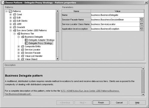
Here, the designer chooses from a list of patterns. In this example, the Business Delegate pattern, as defined in the book Core J2EE Patterns [Deepak, 2003], has been selected. Via the dialog, the designer can specify the class names generated from the template. A link to reference documentation for the pattern appears in the lower pane of the dialog window.
From this template, the classes defined by the pattern are created and added to the active diagram with the relationships between the classes correctly modeled.
Figure 5-10 displays the classes that resulted from the pattern template. As Figure 5-10 illustrates, the classes have been created in strict compliance with the pattern. Together Control-Center has also generated much of the boilerplate code involved in the pattern, leaving the software engineer free to concentrate on the implementation detail.
Working with patterns using a template-driven approach has some distinct advantages over simply building the pattern a class at a time:
The classes are generated in accordance with the guidelines of the design pattern
Templates make patterns easy to apply, which encourages their use
First, the modeling tool ensures the pattern is laid down in compliance with the original specification of the pattern. Like the UML, design patterns are an example of a common vocabulary for software engineers, who can use patterns to describe application designs as well as build with them. Incorrect interpretation of a design pattern negates the advantages of this common vocabulary and can cause confusion, making ongoing maintenance of the application difficult. The use of a pattern template ensures each pattern is applied correctly, thereby removing the opportunity for the designer to misinterpret them in the design.
Having patterns so easily accessible also encourages extensive use of patterns in the design process. A traditional approach would see the designer referring to a pattern’s specification and then tediously defining each class and all the relationships. With a modeling tool, a comprehensive list of patterns is only a few keystrokes away. The designer not only can apply patterns quickly to a design but also can experiment with different patterns and pattern combinations as part of the model.
note
Template use is analogous to painting a room in a house. Painting a wall with a narrow, fine brush would get the job done but would take all day. A far more practical tool than the small brush for this task would be a wide paint roller, which would see the job completed in considerably less time. Pattern templates are therefore our software equivalent of a paint roller.
In addition to providing templates for the established design patterns, the modeling tool should allow designers to create their own pattern templates. This feature enables designers to build the experience of quality designs gained from other projects into the modeling tool. If the modeling tool is used as part of a team environment, these patterns become available to the rest of the team, thereby sharing valuable design knowledge among the group.
This chapter has extolled the virtues of modeling techniques and modeling tools. The use of models in software development offers significant advantages to the software engineer. Modeling tools underpin the development of software models and enable a model-centric approach to software development.
Despite the benefits of modeling tools, their use is far from commonplace on development projects. These next sections examine some of the reasons projects are seemingly unable to make effective use of modeling tools.
Animal rights campaigners spread the message that a dog is for life, not just for Christmas. Anyone buying a modeling tool would do well to heed this advice. Research has shown that like the Christmas puppy, modeling tools in general do not enjoy a lot of use once the wrapping has been removed and the novelty of the new toy has worn off.
This is an expensive white elephant to leave sitting on the shelf. Modeling tools are sophisticated pieces of software, targeted at the enterprise developer, and as such, they often carry enterprise-sized price tags.
The reason many modeling tools fail to win popularity with developers is not because of any shortcomings with the tools themselves; instead it is often because of the purchaser’s unrealistic expectations.
Here are some of the common misconceptions surrounding the capabilities of modeling tools:
Complex code can be replaced with simple diagrams.
Object-oriented design knowledge is not required.
Modeling tools provide an ease-of-use layer on top of J2EE.
They ensure a proper development methodology is followed.
They are easy to use, so no training is needed.
The next sections address each misconception in turn.
A well-thought-out picture can convey a great deal of information succinctly and accurately. The use of diagrams to convey design detail is a central tenet of software modeling. One of the major misconceptions, however, is that the information in a UML diagram can be translated directly into fully functional code and that the UML offers a superior substitute to Java as a programming language.
Modeling tools can generate source code from UML artifacts such as class and interaction diagrams, and yes, the code they generate does save the developer effort. However, this level of code generation falls far short of the concept of executable UML, whereby the entire system is maintained purely in model form. The UML is simply not expressive enough to describe a system to the level at which it can be executed directly.
Models and modeling tools are not a replacement for developers, and the concept of fully executable UML is still more of a research project than a viable commercial reality.
Buying a state-of-the-art modeling tool will not make you a skilled object-oriented designer. If you cannot exhibit artistic flair with a box of colored crayons, then you are equally unlikely to prove a talented artist with the latest computer graphics package.
warning
Applying modeling techniques without staff skilled in object-oriented design will cost time, not save it.
Modeling tools support designers in developing object-oriented software. They enable designers to use their hard-earned object-oriented design skills productively. Consequently, modeling tools are best used by designers already conversant with object-oriented development practices. They are not a tool for novices, nor are they a teaching aid.
Modeling tools do not provide an abstraction layer upon the underlying platform for which the software is targeted. For our purposes, the underlying platform is J2EE. While some modeling tools cater to the development of J2EE components, these tools do not remove the need for the software engineer to understand the intricacies of J2EE. It is the architect’s responsibility to apply his or her knowledge of J2EE when designing with the tool; the tool will not do this for the architect.
Interestingly, much work is ongoing in this area to make models platform-neutral. In this way, code can be generated directly from the model for any given platform. This approach is known as Model-Driven Architecture (MDA), and the technology is still in its infancy. If the goals of MDA can be realized, a significant step forward in terms of software development productivity can be made.
Note
Model-Driven Architecture is discussed in Chapter 8.
Modeling tools are process-agnostic in that they do not support any particular software development methodology. Instead, it is left to the project team to use the modeling tool as part of the chosen development process.
Perhaps the confusion that modeling tools come with a ready-made methodology has come about because of the association with the UML and the IBM Rational Unified Process. Booch, Rumbaugh, and Jacobson, who formulated the UML, also combined their own respective development methodologies to create the Unified Process that later became the IBM Rational Unified Process. The UML and the RUP, while quite distinct in their uses, are synonymous in the minds of many developers. Because the UML is common to virtually all modeling tools, the leap is often made that by using a modeling tool, a RUP-like process is intrinsically followed. This is certainly not the case. Models are complementary to the development methodology, not a replacement.
Getting the most out of a modeling tool involves being aware of all the tool’s features and understanding how to use those features on a development project. A common failing is to introduce project teams to new tools with no supporting information on how those tools can assist the team in the process of developing quality software.
Training on the use of the tool, possibly in conjunction with general training on UML notation, helps to educate the development team on the benefits the chosen modeling tool brings to the software development process. Training also helps teams buy in to the concept of working with models.
Given that modeling tools are not always successfully utilized on development projects, this section examines what steps can be taken to ensure that any investment in such tools generates a respectable return.
Here are several guidelines that take the risk out of adopting modeling methods and modeling tools, and enable the benefits of a model-driven approach to be fully appreciated by the development team.
Moving to a model-based development approach need not involve purchasing the most expensive and extensively featured modeling tool on the market. A simple paper-based approach is one method for gradually introducing modeling methods to the team. Encourage your peers to discuss designs using the UML diagrams introduced in this chapter. Consider using a freely available community-edition modeling tool in your early modeling efforts.
Information and experience gained from these reduced feature-set tools can be used in preparing a business case to management for upgrading to a more sophisticated product. The knowledge gained from the low-end product should provide valuable ammunition for your cause.
If you are new to modeling, don’t let a modeling tool be your first introduction to the practice. Make sure you understand the basics of the UML and the rationale behind modeling methods before you start grappling with the idiosyncrasies of a particular modeling tool. A modeling tool will make you a more productive modeler; however, despite what the marketing material may claim, it is not a teaching aid.
Be wary of purchasing a modeling tool for just one person on the team. Design is a team effort, and having only a single license for a modeling product means designs cannot be worked on collectively. Models are an effective mechanism for communication, and good communication is essential for a successful project. Give everyone on the design team the means to communicate.
Do not introduce modeling methods into the pressure-cooker environment of a new project and expect to see spectacular results. Be realistic. Allow yourself and the team time to become familiar with both the methods and the modeling tool before putting them into practice on a project with a tight timeframe. Learning modeling skills takes time and must be accounted for on any project plan. A good strategy is to bring in a mentor to help accelerate the learning process.
Making models part of the development process offers significant benefits. Models help to
Improve communication of the system design among the project team
Explore system requirements and behavior with the customer
Improve the entire team’s understanding of how the system operates
Validate the design against the primary use-case scenarios
Using modeling tools to construct UML diagrams further enhances the benefits of a model-based approach to development:
Roundtrip support keeps models current on iterative development projects.
Checking of UML syntax helps ensure the accurate communication of designs.
Validation of the design using interaction diagrams provides an early alert of design issues.
The next chapter looks at code generation techniques and investigates how code generators provide an effective mechanism for incorporating change on a project.
Martin Fowler’s book UML Distilled [Fowler, 2003] covers the different UML models and the associated UML notation.
The designers of the UML have also written a comprehensive guide to their creation, The Unified Modeling Language User Guide [Booch, 1998].
Scott Ambler is a keen advocate of modeling techniques and devised his own development process based on models. Information on his Agile Modeling process can be found at http://www.agilemodeling.com.