A console (also known as a board, mixer, or, in Europe, mixing desk) takes input signals and amplifies, balances, processes, combines, and routes them to broadcast or recording.[1] Many consoles also store operational data. Mixers do essentially the same thing, but the console is larger in most models, is more complex, performs several processing functions, and is designed essentially for use in the studio. In the majority of modern console systems, many if not most functions are computer-assisted. The mixer is smaller and, compared with studio-size consoles, performs limited processing operations, which may or may not be computer-assisted.
Although mixers can be used anywhere, their size and compactness make them highly portable, so they are typically used away from the studio, in the field. Some are equipped with a built-in recorder (see 13-19). Mixers are covered in Chapter 13.[2]
Consoles today are available in various configurations; they use different technologies and are designed for specific production purposes. There is no one system that can be used as a generalized example of all the systems out there. They can be grouped into broad categories, however. A console may be analog or digital; appropriate for on-air broadcast, production, or postproduction; and software-based and used as a virtual console with a digital audio workstation.
In an analog console, audio signals flow in and out of physical modules through inboard wires and circuits. To add flexibility to the signal flow, an inboard patch bay consisting of jacks wired to the console’s components facilitates the routing and the rerouting of signals within the console and to and from studio outboard equipment. Patch cords plug into the jacks to direct signal flow (see “Patching” later in this chapter).
In a digital console, incoming analog audio signals are converted to digital information at the inputs, and interfaces handle the routing and the signal processing. If the audio entering the console is already digitized, of course no conversion is necessary. Routing and rerouting of signals are also handled by patching, but operations are managed through the console’s interfaces, which are inboard. There are no jacks or patch cords needed to effect connections.
Modern analog and digital consoles are capable of data storage, and the operation of many analog models is computer-assisted. Digital consoles almost always incorporate at least some computer-assisted functions.
A virtual console is a simulated console displayed on a computer screen that is part of the software of a digital recording program. Its functions are similar to those of a conventional console and are controlled by a mouse or control surface (see “Control Surfaces” later in this chapter).
A console used for on-air broadcasts (including podcasts—see Chapter 18) is designed to handle audio sources that are immediately distributed to the audience. Whatever is not live has been already produced and packaged and requires only playback. Therefore an on-air broadcast console needs more controlling elements to manage rapid transitions. In a radio disc jockey program, those transitions are between disc jockey, music, and spot announcements; in an interview or panel program, they are among host, guest(s), call-ins from listeners, and spot announcements. In radio and television news, there are the studio-based anchor(s), field reporters, and recorded segments to deal with. Mix-minus (covered in Chapter 13) is essential for creating custom mixes for reporters waiting to come on the air from the field. Snapshot memory of console parameters enables event storage and recall of a program’s baseline settings at the beginning of the program’s next broadcast, so operators do not have to take the time to reset those parameters manually.
The on-air broadcast console and consoles in general have at least three basic control sections: input, output, and monitor. The input section takes an incoming signal from a microphone, CD player, recorder, or phone-in caller. Each input channel is configured for either low-level sound sources, such as microphones, or high-level sound sources, such as recorders and CD players. The loudness level of each channel is regulated by a fader (usually sliding, as opposed to rotary). A delegation switch on each channel can either turn off the signal flow or route it to one of three destinations: program, which sends it to the console’s output; to the monitor section so that it can be heard; or to a second monitor system, called audition or cue. The audition or cue system makes it possible to listen to program material while preparing it for broadcast, without it being heard on the air.
At the output section, there is a master fader to handle the combined signals feeding to it from the input channels. This is the last stop at the console before the output signal is further routed and transmitted.
For stereo, faders usually carry a tandem left/right stereo signal. Some on-air consoles may use stereo pairs, with the left fader carrying the left signal and the right fader carrying the right signal.
Input and output signals are heard as sound through monitor loudspeakers. As they pass through the console, however, they are in the form of voltage. Therefore meters are necessary to measure the voltages in the input and output sections. By using the fader, these voltages can be kept within acceptable limits. (Meters are discussed later in this chapter.)
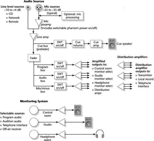
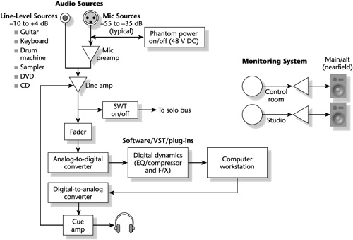
On-air consoles include a variety of other features, such as equalization, compression, and limiting, depending on the complexity of the broadcast and the need for signal processing and programmed functions. A console designed for broadcast may also be able to do double duty and handle off-air production needs as well, as explained in the following section. 5-1 displays the signal flow of a basic generic broadcast console.
Production consoles are necessary for producing and postproducing music, film, and video sound tracks, sports, and such live-to-recording programs as parades and variety, talk, and awards shows. They must be capable of handling many sound sources simultaneously and employing the diversity of tasks involved in dynamics processing—equalization, compression, noise gating, reverberation, and delay—necessary for “sweetening” and mixing.
Automation is a necessity. It allows operational data from production sessions to be stored on and retrieved from disk. In film and television, automated panning facilitates the matching of movement to picture. A production console for music recording often requires a number of submixers to premix groups of similar voicings, such as strings, backup vocals, and the components of a drum set. Network TV news is essentially a one- or two-mic show, yet with recorded music intros, reports from the field, and interviews, it can easily occupy the many inputs of a production console. Specialized, compact consoles with integrated machine interface systems are required to handle the unique requirements of automated dialogue replacement (ADR) and Foley sound-effects recording. Consoles used for music and postproduction mixes in film and television must have sufficient capabilities to handle the many tracks of musical instruments, dialogue, and sound effects as well as the stereo and surround-sound processing.
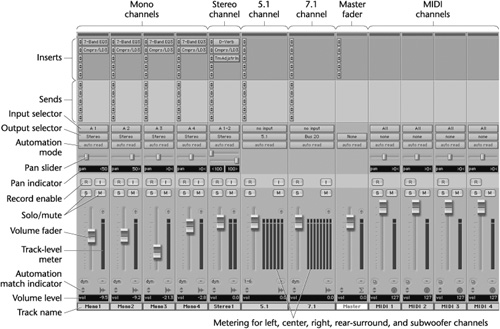
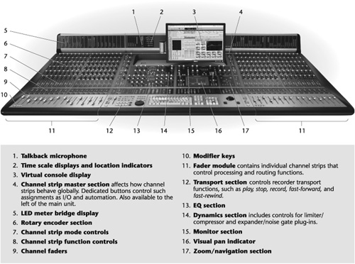
The number of features on a production console and how they interface vary with the console’s purpose and whether it is analog or digital. Regardless of these factors, however, most production consoles incorporate a number of basic functions (see 5-2).
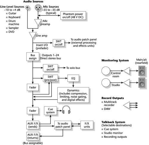
In the following list, sequence of functions, signal flow, section designations, groupings, and terminology will differ depending on the console architecture and manufacturer. But most of the features are found on the majority of production consoles.
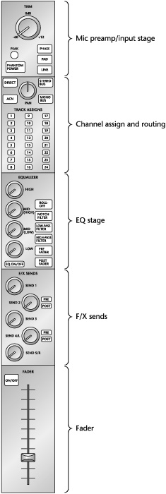
Input/output (I/O) channel. —During recording, the input/output, or I/O, channel strip processes and delegates incoming signals and sends them on for recording (see 5-3). During mixing the I/O section processes signals from the recorder and routes them to the master section, where they are combined into mono, stereo, or surround channels and routed for the master recording.
Input selector control. —You will recall that two types of signal sources feed to input modules: low-level, such as microphones, and high-level, such as recorders and CD players. The input selector control delegates which type of signal source enters the input section.
Phantom power. —Phantom power, when activated, provides voltage (48 V DC, or direct current) for capacitor mics, eliminating the need for batteries.
Microphone preamplifier. —A microphone signal entering the console is weak. It requires a mic preamplifier to increase its voltage to a usable level.
A word about mic preamps in consoles: Whether the audio is analog or digital, each component in the signal flow must be as noise-free as possible. Given the low-noise, high-sensitivity, and high-SPL specifications of many of today’s microphones, it is important that the mic preamp be capable of handling a mic’s output without strain. If the console’s preamp is inadequate to meet this requirement, it is necessary to use an outboard mic preamp (see 5-4).
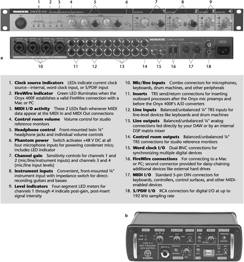
5-4 Microphone preamplifiers. (a) Four-microphone preamplifier and its features. (b) This is a stereo mic preamp with phantom power, switchable to a middle-side (M-S) matrix. It includes two low-cut filters (20 Hz and 150 Hz) and can be AC- or battery-powered. TRS = tip, ring, sleeve.
Inboard or outboard, a good-quality mic preamp must deliver high gain, low circuit noise (hiss), high common-mode rejection ratio (CMRR)—the ratio between signal gain and interference rejection—freedom from radio frequency (RF) interference, and freedom from ground-induced buzz or hum.
Console preamps may be located many feet from a microphone. The more circuitry a signal navigates, the greater the chance for increased noise. By placing a mic preamp in close proximity to a microphone and amplifying mic signals to the required levels before they travel very far, noise can be dramatically reduced. A mic preamp should be stable at very low and/or very high gain settings. The CMRR values should be at least 80 to 90 dB at crucial frequencies, such as 50 to 60 Hz and above 10 kHz—not just at 1 kHz, the only frequency at which many mic preamps are measured.
Trim or gain. —The trim is a gain control that changes the input sensitivities to accommodate the nominal input levels of various input sources. Trim boosts the lower-level sources to usable proportions and prevents overload distortion in higher-level sources.
Pad. —A pad reduces the power of a signal. On a console it is placed ahead of the mic input transformer to prevent overload distortion of the transformer and the mic preamplifier. It is used when the trim, by itself, cannot prevent overload in the mic signal. The pad should not be used otherwise because it reduces signal-to-noise ratio.
Overload indicator. —The overload indicator, also called a peak indicator, tells you when the input signal is approaching or has reached overload and is clipping. It is usually a light-emitting diode (LED). In some consoles the LED flashes green when the input signal is peaking in the safe range and flashes red either to indicate clipping or to warn of impending clipping.
Polarity (phase) reversal. —Polarity reversal is a control that inverts the polarity of an input signal 180 degrees. Sometimes called phase reversal, it is used to reverse the polarity of miswired equipment, usually microphones, whose signal is out of phase with the signal from a piece of similar equipment correctly wired. Sometimes intentional polarity reversal is helpful in canceling leakage from adjacent microphones or in creating electroacoustic special effects by mixing together out-of-phase signals from mics picking up the same sound source.
Channel assignment and routing. —This is a group of switches on each channel used to direct the signal from that channel to one or more outputs; or several input signals can be combined and sent to one output. For example, assume that three different microphone signals are routed separately to channels 1, 3, and 11 and the recordist wishes to direct them all to channel 18. By pressing assignment switch 18 on channels 1, 3, and 11, the recordist feeds the signals to channel 18’s active combining network and then on to recorder track 18.
An active combining network (ACN) is an amplifier at which the outputs of two or more signal paths are mixed together to feed a single track of a recorder. To save space the assignment switches are sometimes paired, either alternately—1 and 3, 2 and 4, and so on—or adjacently—1 and 2, 3 and 4, et cetera. In relation to stereo, odd numbers are left channels and even numbers are right channels.
Direct switch. —The direct switch connects the channel signal to the channel output, directing the signal to its own track on the recorder, bypassing the channel ACN and thus reducing noise. For example, using the direct switch routes the signal on, say, channel 1 to recorder track 1, the signal on channel 2 to recorder track 2, and so on.
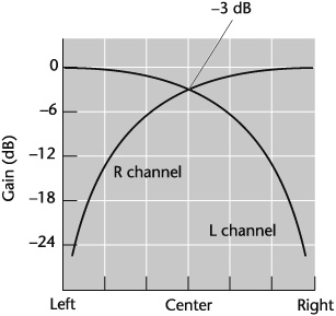
Pan pot. —A pan pot (short for panoramic potentiometer) is a control that can shift the proportion of sound to any point from left to right between two output buses and, hence, between the two loudspeakers necessary for reproducing a stereo image (see 5-5). Panning is also necessary in surround sound to delegate signals left-to-right, front-to-rear (or to rear-side), and rear side-to-side. To hear a signal louder in one bus than in the other, the pan pot varies the relative levels being fed to the output buses. This facilitates the positioning of a sound source at a particular place in the stereo or surround field between or among the loudspeakers.
Equalizer and filter. —An equalizer is an electronic device that alters a signal’s frequency response by boosting or attenuating the level of selected portions of the audio spectrum. A filter alters frequency response by attenuating frequencies above, below, or at a preset point. Most production consoles have separate equalizer controls for selected frequencies grouped in the bass, midrange, and treble ranges. Filters are usually high-pass and low-pass. Upscale consoles have additional equalizer ranges, such as low and high bass and low and high treble, as well as more filter effects. (Equalizers and filters are discussed in Chapter 8.)
The equalization (EQ) module may also have prefader and postfader controls. That is, any equalization or filtering can be assigned before or after the channel fader. Before, or prefader, means that the level control at the EQ module is the only one affecting the loudness of the channel’s equalization. After, or postfader, means that the main channel fader also affects the EQ level. In the postfader mode, the level control at the EQ module is still operational but the main channel fader overrides it.
Dynamics section. —Production consoles may include a dynamics section in each I/O module or, as is the case with most digital models, in a separate, centralized section to which each channel has access. This adds to a console’s signal-processing power and often includes, at least, compression, limiting, and noise gating. Multieffects processing may also include delay, reverb, phasing, and flanging (see Chapter 8).
Channel/monitor control. —Some production consoles include a channel/monitor control in the EQ and dynamics sections that switches the equalizer, dynamics, and usually selected send functions either into the channel signal path for recording or into the monitor signal path for monitoring.
Cue and effects sends (pre- or postfader). —Cue send is a monitor function that routes a signal from an input channel to the headphone, or foldback, system. Foldback is a monitor system that feeds signals from the console to the headphones. The cue send level control adjusts the loudness of the headphone signal before it is sent to the master cue sends in the monitor module.
At the input channel, the cue send can be assigned before or after the channel fader. Before, or prefader cue, means that the level control at cue send is the only one affecting the loudness of the channel’s cue send. After, or postfader cue, means that the main channel fader also affects the cue send level. In the postfader mode, the level control at cue send is still operational, but the main channel fader overrides it.
Pre- and postfader controls add flexibility in providing performers with a suitable headphone mix. In music recording, for example, if the musicians were satisfied with their headphone mix and did not want to hear channel fader adjustments being made during recording, cue send would be switched to the prefader mode. On the other hand, if the musicians did want to hear changes in level at the channel fader, cue send would be switched to the postfader mode.
The effects (F/X or EFX) send, feeds the input signal to an external (outboard) signal processor, such as a reverberation unit, compressor, or harmonizer (see Chapter 8). The effects send module is also called auxiliary (aux) send, reverb send, and echo send.
Effects send can feed a signal to any external signal processor so long as it is wired to the console’s patch bay (see “Patching” later in this chapter). Such a connection is not needed with dynamics processing that is inboard as it is with most modern analog and digital consoles. After the “dry” send signal reaches the outboard signal processor, it returns “wet” to the effects return in the master section for mixing with the main output. The wet signal may also feed to a monitor return system.
The send function also has pre- and postfader controls whereby any signal can be sent before or after the channel fader.
Solo and prefader listen. —Feeding different sounds through several channels at once can create an inconvenience if it becomes necessary to hear one of them to check something. Instead of shutting off or turning down all the channels but the one you wish to hear, activating the solo control, located in each input module, automatically cuts off all other channels feeding the monitor system; this has no effect on the output system. More than one solo can be pushed to audition several channels at once and still cut off the unwanted channels. The solo function is usually prefader. On some consoles, therefore, it is called prefader listen (PFL). In consoles with both solo and prefader listen functions, PFL is prefader and solo is postfader.
Mute (channel on/off). —The mute function, also called channel on/off, turns off the signals from the I/O channel. During mixdown when no sound is feeding through an input channel for the moment, it shuts down the channel or mutes it. This prevents unwanted channel noise from reaching the outputs.
Channel and monitor faders. —The channel and monitor faders control the channel level of the signal being recorded and its monitor level, respectively. During recording, channel levels to the recorder are set for optimal signal-to-noise ratio. Level balances are made during mixdown. To enable the recordist to get a sense of what the balanced levels will sound like, the monitor faders are adjusted to taste, with no effect on the signal being recorded.
It is a paradox in sound production that the way to determine levels in consoles and mixers is visually—by watching a meter that measures the electric energy passing through an input or output. Audio heard through a monitor system is acoustic, but it passes through the console as voltage, which cannot be heard and therefore must be referenced in another way.
That said, a word about determining levels with your eyes: it can be done only to a point. Meters can reflect problems that may not be perceived; or, if they are perceived, a meter may identify the problem when you may not be able to. As such, meters can be considered analogous to test equipment. In recording—and in mixing in particular—however, it is the ear that should determine audio quality and sonic relationships. After all, it is the sound that matters (see Chapter 21).
For sound (acoustic) energy to be processed through electrical equipment, it must be transduced, or converted, into electric energy. Electric energy is measured in decibels in relation to power—dBm—and voltage—dBu or dBv, dBV, and dBFS. It is difficult to fully discuss these measurements here because they involve mathematical formulas and technical terminology that are beyond the scope of this book (see 5-6).
Table . 5-6 Power and voltage measurements in dB.
dBFS (decibel full-scale) is the highest level in digital sound that can be recorded before distortion. On a digital meter, it is 0 dB. For example, -10 dB would be 10 dB below full-scale. |
dBm is the original electrical measurement of power. It is referenced to 1 milliwatt (mW) as dissipated across a 600-ohm (Ω) load. 600 ohms is the standard circuit resistance of a telephone line. (A resistor is a device that opposes the flow of current.) Any voltage that results in 1 mW is 0 dBm, which is the same as 0.775 volt (V) across a 600-ohm impedance. +30 dBm is 1 watt (W); +50 dBm is 100 W. |
dBu, or dBv, is a unit of measurement for expressing the relationship of decibels to voltage—0.775 V to be exact.[*] The u stands for unterminated. The figure comes from 0 dBm, which equals 0.775 V. dBu is a more flexible reference than dBm because it permits use of the decibel scale to obtain a relative level without regard to a standard impedance, that is, 600 ohms. It is a measurement most useful in professional audio. |
dBV is also a measure of voltage but with decibels referenced to 1 V. This measurement is used where the dBm—600 ohm/1 mW—value is impractical, as it is with the measurement of microphone sensitivity where the zero reference is 1 V. +10 dBV is equal to 20 V. Otherwise, dBV is not often used in professional audio. |
[*] Originally, the reference symbol dBu was designated dBv, but because dBv was often confused with dBV it was changed to dBu. Both are still used—dBu mainly in the United States, and dBv mainly in Europe. |
In measuring an electric circuit, a foremost concern is impedance—that property of a circuit, or an element, that restricts the flow of alternating current (AC). Impedance is measured in ohms (Ω), a unit of resistance to current flow. The lower the impedance in a circuit, the better.
The volume-unit meter has been a mainstay for decades and is still found on equipment in use today. But on most new consoles and recording equipment, it is rarely incorporated. The preferred meters today are peak indicators (see “Peak Meters” later in this section).
The volume-unit (VU) meter is a voltage meter originally designed to indicate level as it relates to the human ear’s perception of loudness. It reflects a signal’s perceived volume, but it is not fast enough to track rapid transients. With a complex waveform, the VU meter reads its average loudness level and less than the waveform’s peak voltage. Hence there is headroom built into a console using VU meters so that a signal peaking above 0 level will not distort. (The VU meter uses a linear scale wherein 100 percent of modulation is equal to 0 VU on the volume-unit scale.) Headroom is the amount of level equipment can take, above working level, before overload distortion occurs. For these reasons and given the fact that with digital sound there is no headroom—a level over 100 percent of modulation will distort—the VU meter cannot provide the more exacting measures required for signal processing and recording that peak indicators can.
Two calibrated scales are on the face of the VU meter: a percentage of modulation scale and a volume-unit scale (see 5-7). A needle, the volume indicator, moves back and forth across the scales, pointing out the levels. The needle responds to the electric energy passing through the VU meter. If the energy level is excessively high, the volume indicator will pin—hit against the meter’s extreme right-hand side. Pinning can damage the VU meter’s mechanism, rendering the volume indicator’s reading unreliable.
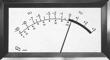
Percentage of modulation is the percentage of an applied signal in relation to the maximum signal a sound system can handle. It is a linear scale wherein 100 percent of modulation is equal to 0 VU on the volume-unit scale. Therefore 30 percent of modulation is equal to slightly less than –10 VU, 80 percent of modulation is equal to -2 VU, and so on.
Any sound below 20 percent of modulation is too quiet, or in the mud; and levels above 100 percent of modulation are too loud, or in the red. (The scale to the right of 100 percent is red.) As a guideline the loudness should “kick” between about -5 and +1, although the dynamics of sound make such evenness difficult to accomplish, if not aesthetically undesirable. Usually, the best that can be done is to ride the gain—adjust the faders from time to time so that, on average, the level stays out of the mud and the red. Fader movements can also be automated (see “Console Automation” later in this chapter).
When manually operating the faders, ride the gain with a light, fluid hand and do not jerk the faders up and down or make adjustments at the slightest fall or rise in loudness. Changes in level should be smooth and imperceptible because abrupt changes are disconcerting to the listener, unless an abrupt change is called for in, say, a transition from one shot to another.
When the VU meter is in the red, it is a warning to be cautious of loudness distortion. All modern consoles with VU meters are designed with headroom so that a signal peaking a few decibels above 0 VU will not distort.
Because a VU meter is designed to reflect a signal’s perceived loudness, it does a poor job of indicating transient peaks, which is a main reason why peak meters are preferred.
Whereas the VU meter is mechanical, most peak meters are electronic. Their rise time is quite fast because there is no mechanical inertia to overcome. A peak meter is able to track peak program levels, thereby making it a more accurate indicator of the signal levels passing through the console and a safer measure when dealing with digital audio.
Peak meters read out in bargraphs, using LED or plasma displays.
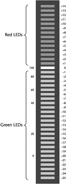
LED Meters. —LEDs are small light sources (LED stands for light-emitting diode). The meters are arranged horizontally or vertically. Usually, green LEDs indicate safe levels and red ones register in the overload region. On professional equipment the LEDs are about 2 dB apart, so resolution is fair (see 5-8).
Plasma Displays. —Plasma displays are columns of light that display safe levels in one color, usually green, and overload levels in red. They are more complex than LED meters and have excellent resolution, with an accuracy of 1 dB. One version of a plasma display meter is roughly analogous to a VU meter and peak program meter (see 5-10) combined, thereby establishing a relationship between average and peak levels (see 5-9).
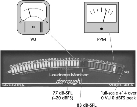
5-9 Loudness meter. This meter is roughly analogous to a VU meter and a peak program meter combined. It establishes a relationship between the root mean square (RMS) and the peak content of a signal. When riding the gain for balanced loudness, peaks should be driven to the brink of the top set of three LEDs (red), while the RMS should be driven to the brink of the center set of three LEDs (red). This is defined as relative loudness, in 1 dB steps. When the signal peaks in the red, the levels should be reduced slightly.
In modern consoles meters also have the capability of measuring more than just output signal levels. Controls on the meter panel can be assigned to read bus, cue send, cue return, and monitor mix levels.
Another type of peak indicator is the peak program meter (ppm) (see 5-10). With the ppm, as signal levels increase there is a warning of impending overload distortion. The level indicator makes this easier to notice because its rise time is rapid and its fallback is slow.
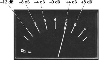
5-10 Peak program meter with equivalent dB values. Dual-movement ppms with two indicators are for two-channel stereo applications.
The ppm’s scale is linear and in decibels, not volume units. The scale’s divisions are 4 dB intervals, except at the extremes of the range; and zero-level is 4, in the middle of the scale.
One goal in processing audio through the signal chain is to make sure that the levels at each stage are optimal. Given the several stages in the sound chain, from microphone to console to recording to mixing to mastering, this is easier said than done. With a console alone, there are a number of reference and overload scales for analog and digital signal levels. They involve a great deal of math that is beyond the scope of this book.
In general, however, there are approaches to optimizing level control in consoles using the available metering. Because just about all production today is handled in the digital domain and there is no headroom with digital signal processing, it makes sense to set the loudest levels below 0 level to avoid clipping—distortion. How far below depends on the dynamics of the audio material. Bear in mind that setting levels too low could create signal-to-noise problems with quiet passages.
Meters in digital audio consoles are calibrated in decibel full-scale (dBFS), a unit of measurement for the amplitude of digital audio signals. Zero dBFS occurs when all the binary bits that make up the digital signal are on, that is, are read as 1’s (as opposed to 0’s, when the digital signal is off). It is the highest digital level that can be encoded, so anything above 0 dBFS will clip. Therefore setting the digital level at, say, –20 dBFS provides a headroom of 20 dB before overload distortion occurs.
Still another measuring system has been developed and proposed by mastering engineer Bob Katz. Called the K-system, it integrates measures of metering and monitoring to standardize reference loudness.[4] Apparently, many recordists do not find peak meters all that reliable and are using VU meters once again. The K-system is an attempt to establish a reliable, standard 0-level measurement that means the same thing to everyone.
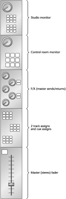
The master section contains the master controls for the master buses, the master fader, the master effects sends and returns, level and mute controls, meters, and other functions (see 5-11).
Master buses. —After a signal leaves an input/output module, it travels to its assigned bus(es). In many consoles these signals may be grouped for premixing at submaster buses before being finally combined at the master bus(es). There may be any number of sub-master buses, but usually there are only a few master buses because final output signals are mixed down to a few channels, such as two-channel stereo and six- (or more) channel surround sound.
Master fader. —The master fader controls the signal level from the master bus to the recorder. Most master faders are configured as a single fader carrying a tandem left/right stereo signal; some are configured as a stereo output pair with the left fader carrying the left signal and the right fader carrying the right signal. A console may have two, four, eight, or more such faders or sets of faders to handle stereo and surround sound. Sometimes there is a mono master fader as well.
Master effects sends (aux send, reverb send, and echo send). —The effects sends from the I/O channels are first routed to the master effects sends before being output to an outboard signal processor.
Master effects returns (aux return, reverb return, and echo return). —Signals routed to an outboard signal processor from the master sends are returned at the master returns and mixed with the main program signal.
Level, mute, PFL, solo, and pan pot. —Each master aux send and aux return usually has a level control and a mute switch. The master returns also usually have PFL, solo, and pan controls.
Peak metering. —Most modern production consoles provide peak metering for each master fader; a mono meter to indicate the level of a summed stereo signal; a phase meter to show the phase relationship between the left and right stereo signals or among the surround signals; metering to monitor surround-sound levels; and metering to display master send and/or return levels. Some consoles also have meters for the control room monitor outputs.
Monitor functions, such as setting monitor level and panning for each channel, may be performed by the I/O module. The monitor section, among other things, allows monitoring of the line or recorder input, selects various inputs to the control room and studio monitors, and controls their levels.
Recorder select switches. —These switches select a recorder for direct feed to the monitor system, bypassing the I/O controls. There may also be aux in switches for direct feeds to the monitor system from other sound sources such as a CD player or a recorder.
Send switches. —These route signals from the sends to the input of the control room or studio monitors or both.
Mix switches. —These select the mix input (i.e., stereo or surround sound) for the monitor system.
Speaker select switches. —These select the control room or studio loudspeakers for monitoring. There is a level control for each set of loudspeakers. Monitor sections also have a dim switch for the control room monitors. Instead of having to turn the monitor level down and up during control room conversation, the dim function reduces monitor level by several decibels or more at the touch of a button.
A monitor section may also have a pan pot, mutes for the left and right channel signals to the control room, and a phase coherence switch. The phase coherence switch inverts the left-channel signal before it combines with the right-channel signal. If the stereo signals are in phase, sound quality should suffer, and, in particular, the sonic images in the center (between the two loudspeakers) should be severely attenuated. If the phase coherence check improves the mono signal, there is a problem with the stereo signal’s mono compatibility.
Additional features found on most consoles include talkback, slate, and oscillator.
Talkback. —The talkback permits the recordist in the control room to speak to the studio performers or music conductor or both via a console microphone. The talkback may be directed through the studio monitor, headphones, or a slate system.
Slate/talkback. —Many multichannel consoles also have a slate feature that automatically feeds to a recording anything said through the talkback. It is a convenient way to transcribe information about the name of the recording, the artist, the take number, and so on.
Oscillator. —An oscillator is a signal generator that produces pure tones or sine waves (sound waves with no harmonics or overtones) at selected frequencies. On a console it is used both to calibrate the console with the recorder so that their levels are the same and to put reference tone levels on recordings.
In general, a channel strip refers to one channel (usually input) of a console. In the past the sound quality of some console channel strips have been so highly regarded that they were ordered separately from the console manufacturer and rigged to a power supply and input/output connections for stand-alone use. A microphone could be plugged directly into the channel strip and the signal sent directly to a recorder, thereby producing a purer and far less complex signal path while eliminating the need to deal with a larger console.
Today stand-alone and plug-in channel strips are so popular that they have become a separate product category. They may include some or most of the functions usually found in most conventional and virtual console channel strips, such as a microphone preamp, equalization, compression, limiting, de-essing, and noise-gating (see 5-12 and 5-13).
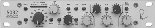
5-12 Stand-alone channel strip. This rack-mountable model is designed to reproduce the sound from vintage Neve console models. It includes a mic preamp, a three-band equalizer, high- and low-frequency shelving, high-pass filters, and phantom power. The silk control is designed to reduce negative feedback and adjust the frequency spectrum to provide a more musical sound.
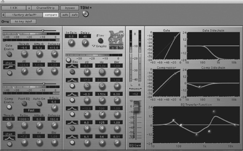
5-13 Channel strip plug-in. This software from Metric Halo includes input gain and trim, polarity reversal, a six-band parametric equalizer, high- and low-frequency shelving, expander/gate, compressor, delay, and time alignment; it also displays detailed visual feedback about the effects of the processing applied.
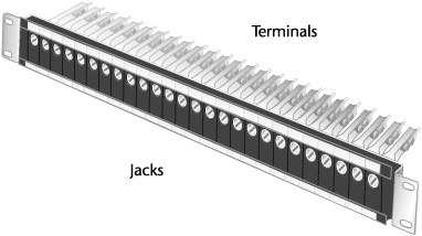
Audio facilities require flexibility in sending signals to various components within the console and to and from outboard equipment in the control room.[5] In studios where active components are not wired directly to one another but to the console or outboard gear or both, one or more patch bays are required. A patch bay is a central terminal that facilitates the routing of sound through pathways not provided in the normal console design. Each hole in the patch bay (or patch panel), called a jack, becomes the connecting point to the input or output of each electronic component in the sound studio (see 5-14). Patching is the interconnecting of these inputs and outputs using a patch cord (see 5-15 and 5-16). In this context a patch bay is more like an old-fashioned telephone switchboard.
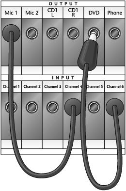
5-15 Use of patch bay. Any sound source wired to the patch panel can be connected to any other one with a patch cord plugged into the appropriate jack.
In digital consoles there is no separate patch bay. Patching is handled internally without the need for special wiring or patch cords (see “Digital Consoles” later in this chapter). Control surfaces can handle signal routing using network routers (see “Control Surfaces” later in this chapter).
In a well-equipped and active analog facility, the patch bay could become a confusing jungle of patch cords. In all studios, regardless of size and activity, a signal travels some paths more often than others. For example, it is more likely that a signal in a console will travel from mic (or line) input to pan pot to equalizer to assignment control to fader, rather than directly from mic (or line) input to output bus. It is also more likely that a signal will travel from mic to console to recorder rather than directly from a mic to a recorder.
As a way of both reducing the clutter of patch cords at the patch bay and simplifying production, terminals wired to certain equipment can also be wired, or normaled, to one another. A normal connection is one that permits a signal to flow freely among components without any patching. To route a signal through components that have terminals not normaled or wired to one another, patch cords are put in the appropriate jacks to break normal—that is, to interrupt the normal signal flow—thus rerouting the signal. In some patch bays, normaling can be done manually, without the need for rewiring.
The ability to reroute a signal is also advantageous when equipment fails. Suppose a microphone is plugged into studio mic input 1, which connects directly to console channel 1, and channel 1 becomes defective. With all inputs and outputs connected at the patch bay, the defective console channel 1 can be bypassed by patching the output from studio mic input 1 to any other working console channel.
Here are some other features of patch bays.
Input/output. —Patch bays are usually wired so that a row of input jacks is directly below a row of output jacks. By reading a patch bay downward, it is possible to get a good idea of the console’s (or studio’s) signal flow.
Full-normal and half-normal. —Input jacks are wired so that a patch cord always interrupts the normal connection. These connections are called full-normal. Output jacks may be wired as either full-normal or half-normal—connections that continue rather than interrupt signal flow. Hence a half-normal connection becomes a junction rather than a switch.
Multiple. —Most patch bays include jacks called multiples, or mults, that are wired to one another instead of to any electronic component. Multiples provide the flexibility to feed the same signal to several different sources at once.
Tie line. —When the only patch bay in a control room is located in the console, the other control room equipment, such as CD and DVD players and signal processors, must be wired to it to maintain flexibility in signal routing. Tie lines in the patch bay facilitate the interconnecting of outboard devices in the control room. When a control room has two patch bays, one in the console and one for the other control room equipment, tie lines can interconnect them. The tie line is also used to interconnect separate studios, control rooms, or any devices in different locations.
Do not patch mic-level signals into line-level jacks and vice versa. The signal will be barely audible in the first instance and will distort in the latter one.
Do not patch input to input or output to output.
Unless jacks are half-normaled, do not patch the output of a component back into its input, or feedback will occur.
When patching microphones make sure that the fader controls are turned down. Otherwise, the loud popping sound that occurs when patch cords are inserted into jacks with the faders turned up could damage the microphone or loudspeaker element.
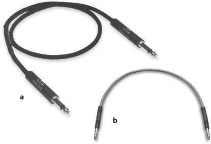
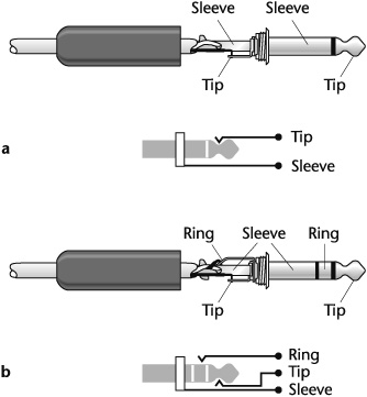
The patch-cord plugs most commonly used in professional facilities are the 1/4-inch phone plug and the bantam phone plug. The bantam (also called mini and tiny telephone) plug, and the smaller patch panel with which it is used, has all but replaced the larger 1/4-inch phone plug and its patch panel (see 5-16).
These plugs are either unbalanced—tip and sleeve—or balanced—tip, ring, and sleeve (see 5-17). An unbalanced audio cable has two conductors: a center wire and a braided shield surrounding it. A balanced audio cable has three conductors: two center wires and a braided shield. The balanced line is preferred for professional use because it is not so susceptible to electrical interference and can be used in long cable runs without undue loss in signal-to-noise ratio.
Instead of hardware-based patch panels, many modern consoles in general and most digital consoles in particular handle patching using computer programming. Routing signals via patching does not require a physical patch bay or cords. At the touch of a few keys, routing information is entered into a programmer, which tells the electronic patch panel to connect the selected signal source to the desired console channel. All patching commands can be stored for future use. Computer patching is convenient, flexible, and tidy. It is worth emphasizing, however, the importance of keeping track of all the patching assignments. Otherwise it could lead to confusion in managing the signal flows.
Given today’s complex production consoles and the myriad procedures involved in mixing many tracks to a few, console automation has become indispensable. It greatly facilitates operations by automatically keeping track of the various mixer settings and by storing the information for recall at any time.
There are four types of automation systems in consoles: voltage-controlled automation, moving-fader automation, software-controlled automation, and MIDI-based automation.
In voltage-controlled automation, fader levels (and other functions) are regulated by two types of amplifiers. The voltage-controlled amplifier (VCA) is used to decrease level, unlike conventional amplifiers that become unstable if operated with loss. It is regulated by external DC voltage. In a typical VCA-equipped console, faders vary the DC control voltage that changes the VCA’s gain in relation to the fader movement. This control voltage is digitized and stored for later retrieval. In addition to fader levels, it is possible to automate channel and group mutes, solo functions, and inboard signal processors, such as the equalizer. The digitally controlled amplifier (DCA) is an amp whose gain is remotely controlled by a digital control signal.
Moving-fader automation, also called flying-fader automation, drives a small servomotor that is attached to the fader instead of using DC voltage to control a VCA. As the control voltages are regenerated, it activates the motor, which moves the fader automatically; no hand-operated assistance is necessary. It is possible to control automatically one fader or groups of faders at the same time.
Software-controlled automation uses specially designed computer programs for console automation. It is usually employed in disk-based recording systems.
Adjustments are made through virtual faders displayed on a video monitor. A virtual control is simulated on a computer monitor and adjusted at the computer keyboard, with a mouse, or by using a touchscreen. More complex programs, in addition to automated level control, also allow automated control of all inboard signal processing, such as equalization, panning, compression, and effects.
MIDI, short for Musical Instrument Digital Interface, is a communications protocol. The digital refers to a set of instructions in the form of digital (binary) data, like a computer program, that must be interpreted by an electronic sound-generating or sound-modifying device, such as a synthesizer, that can respond to the instructions. Interface refers to the hardware connection that permits the control signals generated by one device to be transmitted to another. A specified system of digital commands and hardware interface allows musical instruments and other devices to communicate with one another.
In the same way that MIDI can automate musical instruments, it can also be used to automate console operations, such as fader levels, send and return levels, EQ, and pans. MIDI-automated consoles may physically resemble consoles with conventional automation or may be “black boxes” with input and output jacks. These boxes may use either a virtual console computer graphic interface or dedicated controllers with slides and knobs that control the box through MIDI commands.
MIDI console automation has limitations in handling the large amounts of data that other types of automation do not have. But because many conventional console automation systems are so complex, some recordists turn to MIDI-based automation systems as a simpler alternative.
Two methods are used to handle data changes in console automation: snapshot control and continuous control. With snapshot control the automation system takes an instant reading of the console settings for recall from storage. The reading reflects the state of the console at a particular moment. With continuous control, or dynamic control, the motion of the mixer controls is recorded. Gradual changes of parameters, from small adjustments in level to larger changes such as fades, are stored as they are made over time.
Console automation systems have at least three basic operating modes: write, read, and update. All functions may be used independently on any or all channels.
Write mode. —The write mode is used to create an automated mix. In the write mode, the automation system monitors and stores data from the faders. Only current fader movements are stored in the write mode.
Read mode. —The read mode plays back or recalls the stored automation data. In the read mode, which is also called safe mode, the console’s faders are inoperative. They take their control voltage information only from the stored data on the disk to reproduce the “recorded” fader movements in real time.
Update mode. —The update mode allows the operator to read the stored information at any time and make changes simply by moving the appropriate fader. A new data track is generated from the original data track with the changes that have been made.
Mixing various sounds once they are recorded can be exacting and tedious. It requires dozens, maybe hundreds, of replays and myriad adjustments to get the right equalization, reverberation, blend, spatial balance, timing of inserts, and so on. Comparing one mix with another is difficult unless settings are written down (which is time-consuming) so that controls can be returned to previous positions if necessary. It is not uncommon to discard a mix because someone forgot to adjust one control or decided after a few days to change a few settings without noting the original positions. Then the controls have to be set up all over again. Mixing one song can take many hours or even days; a production can take months.
Console automation greatly facilitates the recordkeeping and the accuracy of mixing; it makes the engineer’s arms “longer.” Many productions are so involved that they would be nearly impossible without automation.
As necessary as automation is in so much of audio production, it also has some disadvantages. It tends to be confusing, even to experienced operators. Some systems are so complex that it is easy to lose track of the many operations necessary to perform a mix, which defeats the purpose of automation. Some systems may not play back exactly what the operator wrote. If the mix is complex, a difference of a few decibels overall may not be perceptible. That would not be the case, however, in more subtle mixes.
Automation systems, like all computer systems, are vulnerable to crashing. Getting the system operational again, even assuming that you had the forethought to make a backup copy of the mix before completion, often involves a frustrating loss of production time and continuity, to say nothing of the financial cost.
An aesthetic concern with automation is “sameness.” Unless an automated mix is done with skill, its dynamics can sound the same from beginning to end.
The disadvantages of console automation notwithstanding, most audio production today would be difficult without it.
Aside from their differences in technologies, the main innovation in digital consoles compared with analog consoles is the divorcing of circuitry from panel controls. The control surface still comprises the familiar controls—faders, equalizer, input selectors, sends, returns, and so on—but there is no physical connection between the controls on the console surface and the audio circuit elements, nor are specific controls necessarily dedicated to particular channels.
With an analog console, the controls in one input/output channel strip must be duplicated for each channel strip in the console. With digital consoles many of these functions pass through a central processor, eliminating the need for duplication and making it possible to increase the number of operations in a smaller surface area. Operational commands are recorded in the system’s memory for recall at any time and are assignable.
For example, instead of having an EQ module in each channel strip, the console is designed into a central control panel to which all channels have access. Select, say, channel 1 and pass its signal through the equalizer in the central control panel; make the desired EQ adjustments, which are recorded in the console’s memory; then move on to, say, channel 2 and pass its signal through the equalizer; make the desired EQ adjustments, which are recorded in the console’s memory; and so on. With most digital consoles today, the same can be done with other dynamic effects that are part of the central control panel, such as compression, limiting, noise gating, and delay, as well as effects sends, monitor levels, and panning. (A pan control may also be included in each channel strip.)
The assignable console design has several advantages over conventional production consoles. In addition to making many more operations possible in a more compact chassis, signals can be handled more quickly and easily because functions are grouped and, with fewer controls, there are fewer operations to perform; patching can be accomplished at the touch of a few keys, inboard, without the need for a patch bay and patch cords (see 5-18).
5-18 Signal flow of a basic generic assignable digital console. Each channel strip is separate and houses a number of functions typical of a channel strip on most consoles. In an assignable console, however, functions such as EQ, compression, noise gating, and delay are located in a central processing unit and can be individually custom-assigned to each channel strip and retained in the console’s memory.
Digital consoles are available in three basic configurations. One configuration is actually an analog console that is digitally controlled. The signal path is distributed and processed in analog form, but the console’s control parameters are maintained digitally.
The second configuration is the all-digital console, which uses two approaches. The analog input signal is first encoded into a digital signal, or it is directly accepted as digital information. In either case, the data are distributed and processed digitally. The output might be decoded back into analog or may remain in digital form, depending on its destination.
A third type of digital mixer is actually a virtual console. As the term suggests, a virtual console is not a console per se but an integrated system that combines a hard-disk computer and specialized software to record and process audio directly to disk. Instead of feeding a sound source to a conventional console, it is fed directly to the computer. The controls are displayed on the computer monitor and look like those of a typical analog console—faders, EQ, panning, sends, returns, and so on (see 5-19). Operations and functions are manipulated using some type of human interface device (HID), such as a mouse, keyboard, joystick, or touchscreen, although these tools are not always suited to the hands-on control associated with various aspects of audio production. Mixing with a mouse and a keyboard can be cumbersome and awkward at best. An increasingly diverse range of HIDs, called control surfaces or work surfaces, provide more tactile means of control across a spectrum of digital audio systems, devices, and software applications.
In much the same way that digital tablet and pen technology liberated graphic artists from the limitations of creating with a keyboard and a mouse, an audio control surface provides a tactual means of controlling the various elements of sound production. Also called a work surface, the design, features, and appearance of such a control surface vary according to its function: from a dedicated virtual instrument or digital signal processing (DSP) plug-in controller to universal and hybrid work surfaces (see 5-20 to 5-22). Generally, there are no actual audio signals present inside a simple control surface, only control circuitry that sends digital instructions to the device doing the actual audio signal processing.
5-20 Control surface designed to facilitate editing of DSP and virtual instrument plug-ins with a variety of different software. This controller may be used as a stand-alone solution or in tandem with other control surface components for analog-style control over tracks and plug-ins.
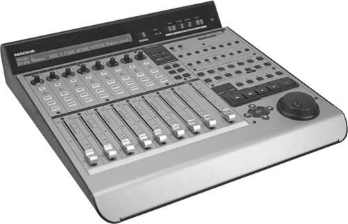
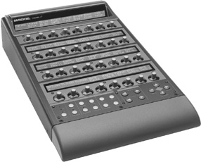
5-21 Universal control surface. This model provides transport, automation, and DSP functions without the need for a mouse or keyboard. Used primarily for mixing, it resembles an analog mixing console. Controls include record, play, stop, fast-forward, rewind, and other frequently used editing functions. A jog/shuttle wheel facilitates positioning and scrub-editing.
Depending on the digital audio workstation environment and the technology employed, control surfaces may function or be configured in different ways. The most popular means of connecting a control surface to a host computer or other peripheral device is via the MIDI standard (see “MIDI-based Automation” earlier in this chapter; see also Chapter 7). Other equipment may support a number of connections: a proprietary interface; a Universal Serial Bus (USB) port; a FireWire cable, which generally provides more rapid data and media transfer and access speeds than USB; or an Ethernet connection.
Universal and hybrid control surfaces often integrate analog and digital audio signals and paths with DSP control capability across compatible programs. Control surfaces can be used in most types of audio production: in performance, from dedicated control over MIDI devices including virtual instruments, synthesizers, samplers, and sequencing software applications; and in recording, mixing, DSP, and automation.
Another use for a control surface is via router connectivity, thereby enabling access to a broadcast station’s or production facility’s entire network of audio sources and assets. A dedicated control surface such as the one shown in 5-23 works with a network router.
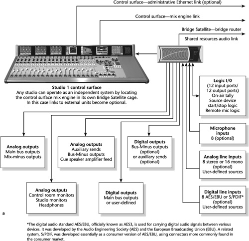

Figure . 5-23 (a) Dedicated control surface and its input and output connections. With this model it is possible to select any combination of input signals in the entire Bridge system and create a multitude of mixes. The system can handle any live broadcast segment or complex, layered production programming. Because of the inboard routing control, all mixes can be directed to any destination in a facility. (b) Detail of an input channel, master section, and dynamics section with a list of features. (c) LCD screens for input, channel status, dynamics, and equalization.
Digital consoles and control surfaces have several advantages over their all-analog counterparts, especially as more and more facets of audio production move into the digital domain. They are virtually distortion- and noise-free; every control move—manual or preprogrammed—is stored and retrieved digitally with a greater degree of accuracy. For example, manipulating a knob or—in the parlance of the control surface—a rotary encoder sends a set of precise, digital instructions to a device. This is far more efficient than manually modulating voltage control through a potentiometer, with all its associated system noise, artifacts, and margin of user error from one move to the next. Control parameters may be combined or matrixed in such a way that one control instruction can direct several preprogrammed functions to occur simultaneously. Physical inboard and outboard patch bays are unnecessary, although limited in control surfaces compared with the routing flexibility in digital consoles; a compact chassis preserves valuable control room space; and, given the variety and the efficiency of operational potential and capacities, compared with their analog cousins, whether the console or control surface is modest or upscale, there are enough models available to suit any budget and production requirement.
Consoles and mixers take input signals and amplify, balance, process, combine, and route them to broadcast, recording, or other destinations in a facility.
The differences between a mixer and a console are that a mixer is small, highly portable, and performs limited processing functions, whereas a console is larger and performs numerous processing functions. In most modern consoles, these functions are computer-assisted.
The term mixer is often used synonymously with console. Some mixers include additional features that are found on consoles, and some small- and medium-format consoles have limited features that could classify them as large mixers.
Consoles today are available in various configurations, use different technologies, and are designed for particular production purposes. A console may be analog or digital; appropriate for on-air broadcast, production, or postproduction; software-based and used as a virtual console with a hard-disk recorder; or it may be a control surface.
Regardless of their design, purpose, and complexity, consoles have at least the three basic control sections: input, output, and monitor. Many consoles have an additional master control section.
The input section takes incoming signals and routes them to the output section.
The output section routes signals to broadcast, recording, or a router.
The monitor section enables signals to be heard.
On-air broadcast consoles, particularly for radio, do not have to be as elaborate as production consoles because most of the audio they handle has been produced already. But modern consoles for radio have sophisticated features, such as digital signal processing (DSP), computer-assisted operations, and routing flexibility.
The features of production consoles generally include the input/output (I/O) section consisting of an I/O channel strip; input selector control; phantom power; microphone preamplifier input module; microphone preamplifier; trim or gain; pad; overload, or peak, indicator; polarity (phase) reversal; channel assignment and routing; direct switch; pan pot; equalizer and filter; dynamics section; channel/monitor control; cue and effects (F/X or EFX) sends (pre- or postfader); solo and prefader listen (PFL); mute (channel on/off); channel and monitor faders; and meters.
For acoustic sound to be processed through electrical equipment, it must be transduced, or converted, into electric energy. Electric energy is measured in decibels in relation to power (dBm) and voltage (dBu or dBv, dBV, and dBFS).
In measuring an electric circuit, a foremost concern is impedance—that property of a circuit, or an element, that restricts the flow of alternating current (AC). Impedance is measured in ohms (Ω), a unit of resistance to current flow. The lower the impedance in a circuit, the better.
The volume-unit (VU) meter is a voltage meter that measures the amount of electric energy flowing through the console. The meter has two scales: percentage of modulation and volume units. Percentage of modulation is the percentage of an applied signal in relation to the maximum signal a sound system can handle.
Peak meters, which today are preferred over the VU meter, track peak program levels, thereby making them a more accurate indicator of signal levels passing through a console.
Peak meters read out in bargraphs using light-emitting diodes (LEDs) or plasma displays.
With the peak program meter (ppm), as signal levels increase there is a warning of impending overload distortion. The level indicator makes this easier to notice because its rise time is rapid and its fallback is slow.
One goal in processing audio through the signal chain is to make sure that the levels at each stage are optimal. Given the several stages in the sound chain, from microphone to console to recording to mixing to mastering, this is easier said than done.
Meters in digital audio consoles are calibrated in decibel full-scale (dBFS), a unit of measurement for the amplitude of digital audio signals. Zero dBFS occurs when all the binary bits that make up the digital signal are on.
The master section includes master buses, the master fader, the master effects sends and returns, level and mute controls, meters, and other functions.
The monitor section includes recorder select, send, mix, and speaker select switches. It may also have a pan pot, mutes, and a phase coherence switch.
Other common features of production consoles include talkback, slate/talkback, an oscillator, and, in analog consoles, a patch bay.
A channel strip refers to one channel (usually input) of a console. It can be ordered separately from the console manufacturer and rigged to a power supply and I/O connections for stand-alone use.
A patch bay is a central routing terminal that facilitates the routing of sound through pathways not provided in the normal console design. The patch bay makes multiple signal paths possible. Patch cords plugged into jacks connect the routing circuits.
The signal paths that are used most often are wired together at the terminals of the patch bay. This normals these routes and makes it unnecessary to use patch cords to connect them. It is possible to break normal and create other signal paths by patching.
Plugs at the end of patch cords are either unbalanced, comprising a tip and a sleeve, or balanced, comprising a tip, ring, and sleeve.
Instead of hardware-based patch panels, many modern consoles in general and all digital consoles in particular handle patching using computer programming.
Console automation makes it possible to automate fader functions, decoding positional information as adjustments in level are made. The data are stored in and retrieved from computer memory.
There are four types of console automation systems in use: voltage-controlled automation, moving-fader automation, software-controlled automation, and MIDI-based automation.
Console automation systems have at least three basic operating modes: write, read, and update.
Digital consoles use the assignable concept in three configurations: in an analog console that is digitally controlled, in an all-digital console, and in a virtual console which is not a console per se but an integrated system that combines a hard-disk computer and specialized software to record and process audio directly to disk.
With digital consoles, instead of individual controls for channel-to-track routing on each channel strip, these functions have been centralized into single sets so they can be assigned to any channel. Once assigned, the commands are stored in the console’s computer, so different functions can be assigned to other channels. There is no physical connection between the controls on the console surface and the audio circuit elements.
A control surface, or work surface, provides external control of a virtual audio environment. There are two main types of control surfaces: general-purpose controllers that can work with a wide range of gear and dedicated controllers that work with specific software.
[1] The different types and models of consoles and control surfaces available today are considerable. Their purposes and particular designs differ. To cover the subject with specificity would be unwieldy. Moreover, the details that apply to one console or control surface may not apply to another. They do have certain functions in common, however. Therefore to deal with the topic manageably, the approach in this chapter is generic; the intent is to cover in general the operational features of the main types of consoles and control surfaces.
[2] Not to get bogged down in terminology, but the term mixer is often used synonymously with console. Some mixers include additional features that are found on consoles, and some small- and medium-format consoles have limited features that could classify them as large mixers.
[4] See Bob Katz, Mastering Audio, 2nd ed. (Boston: Focal Press, 2007), p. 176.
[5] Although patching operations are handled internally in many of the consoles produced today, there are a sufficient number of facilities with equipment that requires patching to warrant coverage here.