CHAPTER 5
INVERSE KINEMATICS
In Chapter 3 we showed how to determine the end effector’s position and orientation in terms of the joint variables. This chapter is concerned with the inverse problem, that of finding the joint variables in terms of the end effector’s position and orientation. This is the problem of inverse kinematics, and it is, in general, more difficult than the forward kinematics problem.
We begin by formulating the general inverse kinematics problem. Following this, we describe the principle of kinematic decoupling and how it can be used to simplify the inverse kinematics of most modern manipulators that are equipped with spherical wrists. Using kinematic decoupling, we can consider the position and orientation problems independently. We describe a geometric approach for solving the positioning problem, while we exploit the Euler angle parameterization to solve the orientation problem.
We also discuss numerical solution of the inverse kinematics using methods based on both the Jacobian inverse and the Jacobian transpose. The Jacobian inverse method is similar to a Newton–Raphson search whereas the Jacobian transpose method is a gradient search method.
5.1 The General Inverse Kinematics Problem
The general problem of inverse kinematics can be stated as follows. Given a 4 × 4 homogeneous transformation
find a solution, or possibly multiple solutions, of the equation
where
specifies the forward kinematics of an n-degree-of-freedom manipulator. Here the homogeneous transformation H represents the desired position and orientation of the end effector, and our task is to find the values for the joint variables q1, …, qn so that ![]() .
.
Equation (5.2) yields sixteen equations to be solved for the n unknown variables, q1, …, qn. However, since the bottom row of both ![]() and H are (0,0,0,1), four of these sixteen equations are trivial and so we can express the remaining twelve nonlinear equations as
and H are (0,0,0,1), four of these sixteen equations are trivial and so we can express the remaining twelve nonlinear equations as
Example 5.1. (The Stanford Manipulator).
Recall the Stanford Manipulator of Section 3.3.5. Suppose that the desired position and orientation of the final frame are given by

To find the corresponding joint variables θ1, θ2, d3, θ4, θ5, and θ6 we must solve the following simultaneous set of nonlinear trigonometric equations:
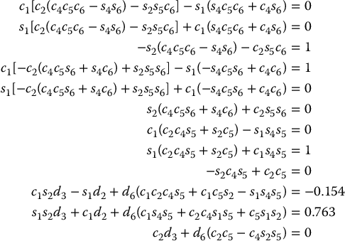
If the values of the nonzero DH parameters are d2 = 0.154 and d6 = 0.263, one solution to this set of equations is given by:
Even though we have not yet seen how one might derive this solution, it is not difficult to verify that it satisfies the forward kinematics equations for the Stanford Arm.
The equations in the preceding example are, of course, much too difficult to solve directly in closed form. This is the case for most robot arms. Therefore, we need to develop efficient and systematic techniques that exploit the particular kinematic structure of the manipulator. Whereas the forward kinematics problem always has a unique solution that can be obtained simply by evaluating the forward equations, the inverse kinematics problem may or may not have a solution. Even if a solution exists, it may or may not be unique. Furthermore, because these forward kinematic equations are in general complicated nonlinear functions of the joint variables, the solutions may be difficult to obtain even when they exist.
The inverse kinematics problem may be solved numerically or in closed form. Finding a closed-form solution means finding an explicit relationship
We first discuss the computation of closed-form solutions. In Section 5.5 we discuss numerical algorithms to find inverse kinematics solutions.
The practical question of the existence of solutions to the inverse kinematics problem depends on engineering as well as mathematical considerations. For example, the motion of the revolute joints may be restricted to less than a full 360 degrees of rotation so that not all mathematical solutions of the kinematic equations will correspond to physically realizable configurations of the manipulator. We will assume that the given position and orientation is such that at least one solution of Equation (5.2) exists. Once a solution to the mathematical equations is identified, it must be further checked to see whether or not it satisfies all constraints on the ranges of possible joint motions.
5.2 Kinematic Decoupling
Although the general problem of inverse kinematics is quite difficult, it turns out that for manipulators having six joints with three consecutive three joint axes intersecting at a point (such as the Stanford Manipulator above), it is possible to decouple the inverse kinematics problem into two simpler problems, known respectively as inverse position kinematics, and inverse orientation kinematics. To put it another way, for a six-DOF manipulator with a spherical wrist, the inverse kinematics problem may be separated into two simpler problems, namely, first finding the position of the intersection of the wrist axes, hereafter called the wrist center, and then finding the orientation of the wrist.
For concreteness let us suppose that there are exactly six degrees of freedom and that the last three joint axes intersect at a point ![]() . We express Equation (5.2) as two sets of equations representing the rotational and positional equations
. We express Equation (5.2) as two sets of equations representing the rotational and positional equations
where ![]() and
and ![]() are the desired position and orientation of the tool frame, expressed with respect to the world coordinate system. Thus, we are given
are the desired position and orientation of the tool frame, expressed with respect to the world coordinate system. Thus, we are given ![]() and
and ![]() , and the inverse kinematics problem is to solve for q1, …, q6.
, and the inverse kinematics problem is to solve for q1, …, q6.
The assumption of a spherical wrist means that the axes z3, z4, and z5 intersect at ![]() and hence the origins
and hence the origins ![]() and
and ![]() assigned by the DH convention will always be at the wrist center
assigned by the DH convention will always be at the wrist center ![]() . Often
. Often ![]() will also be at
will also be at ![]() , but this is not necessary for our subsequent development. The important point of this assumption for the inverse kinematics is that motion of the final three joints about these axes will not change the position of
, but this is not necessary for our subsequent development. The important point of this assumption for the inverse kinematics is that motion of the final three joints about these axes will not change the position of ![]() , and thus the position of the wrist center is a function of only the first three joint variables.
, and thus the position of the wrist center is a function of only the first three joint variables.
The origin of the tool frame (whose desired coordinates are given by ![]() ) is simply obtained by a translation of distance d6 along z5 from
) is simply obtained by a translation of distance d6 along z5 from ![]() (see Table 3.3). In our case, z5 and z6 are the same axis, and the third column of
(see Table 3.3). In our case, z5 and z6 are the same axis, and the third column of ![]() expresses the direction of z6 with respect to the base frame. Therefore, we have
expresses the direction of z6 with respect to the base frame. Therefore, we have

Thus, in order to have the end effector of the robot at the point with coordinates given by ![]() and with the orientation of the end effector given by
and with the orientation of the end effector given by ![]() , it is necessary and sufficient that the wrist center
, it is necessary and sufficient that the wrist center ![]() have coordinates given by
have coordinates given by

and that the orientation of the frame o6x6y6z6 with respect to the base be given by ![]() . If the components of the end effector’s position
. If the components of the end effector’s position ![]() are denoted ox, oy, oz and the components of the wrist center
are denoted ox, oy, oz and the components of the wrist center ![]() are denoted xc, yc, zc then Equation (5.10) gives the relationship
are denoted xc, yc, zc then Equation (5.10) gives the relationship

Using Equation (5.11) we may find the values of the first three joint variables. This determines the orientation transformation ![]() which depends only on these first three joint variables. We can now determine the orientation of the end effector relative to the frame o3x3y3z3 from the expression
which depends only on these first three joint variables. We can now determine the orientation of the end effector relative to the frame o3x3y3z3 from the expression
as
As we shall see in Section 5.4, the final three joint angles can then be found as a set of Euler angles corresponding to ![]() . Note that the right-hand side of Equation (5.13) is completely known since
. Note that the right-hand side of Equation (5.13) is completely known since ![]() is given and
is given and ![]() can be calculated once the first three joint variables are known. The idea of kinematic decoupling is illustrated in Figure 5.1.
can be calculated once the first three joint variables are known. The idea of kinematic decoupling is illustrated in Figure 5.1.
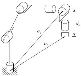
Figure 5.1 Kinematic decoupling in the case of a spherical wrist. The vector oc is the position of the wrist center point and o6 is the position of the end effector, both with respect to the base frame. The wrist center point coordinates do not depend on the wrist orientation variables θ4, θ5, and θ6.
5.3 Inverse Position: A Geometric Approach
For the most common kinematic arrangements that we consider, we can use a geometric approach to find the variables q1, q2, q3 corresponding to ![]() given by Equation (5.10). Since most six-DOF manipulator designs are kinematically simple, usually consisting of one of the five basic configurations of Chapter 1 with a spherical wrist, the geometric approach is simple and effective. Indeed, it is partly due to the difficulty of the general inverse kinematics problem that manipulator designs have evolved to their present state.
given by Equation (5.10). Since most six-DOF manipulator designs are kinematically simple, usually consisting of one of the five basic configurations of Chapter 1 with a spherical wrist, the geometric approach is simple and effective. Indeed, it is partly due to the difficulty of the general inverse kinematics problem that manipulator designs have evolved to their present state.
In general, the complexity of the inverse kinematics problem increases with the number of nonzero DH parameters. For most manipulators, many of the ai, di are zero, the αi are 0 or ± π/2, etc. In these cases especially, a geometric approach is the simplest and most natural. The general idea of the geometric approach is to solve for joint variable qi by projecting the manipulator onto the xi − 1 − yi − 1 plane and solving a simple trigonometry problem. For example, to solve for θ1, we project the arm onto the x0 − y0 plane and use trigonometry to find θ1. We will illustrate this method with two important examples: the spherical (RRP) and the articulated (RRR) arms.
5.3.1 Spherical Configuration
We first solve the inverse position kinematics for a three degree of freedom spherical manipulator shown in Figure 5.2, with the components of ![]() denoted by xc, yc, zc. Projecting
denoted by xc, yc, zc. Projecting ![]() onto the x0 − y0 plane, we see that
onto the x0 − y0 plane, we see that

Figure 5.2 First three joints of a spherical manipulator.
in which Atan2 denotes the two-argument arctangent function defined in Appendix A. Note that a second valid solution for θ1 is
Of course, this will, in turn, lead to a different solution for θ2.
These solutions for θ1, are valid unless xc = yc = 0. In this case, Equation (5.14) is undefined and the manipulator is in a singular configuration, in which the wrist center ![]() intersects z0 as shown in Figure 5.3. In this configuration any value of θ1 leaves
intersects z0 as shown in Figure 5.3. In this configuration any value of θ1 leaves ![]() fixed. There are thus infinitely many solutions for θ1 when
fixed. There are thus infinitely many solutions for θ1 when ![]() intersects z0.
intersects z0.

Figure 5.3 Singular configuration for a spherical manipulator in which the wrist center lies on the z0 axis.
The angle θ2 is given from Figure 5.2 as
where r2 = x2c + yc2 and x = zc − d1.
The linear distance d3 is found as
The negative square root solution for d3 is disregarded and thus in this case we obtain two solutions to the inverse position kinematics as long as the wrist center does not intersect z0.
5.3.2 Articulated Configuration
We next consider the elbow manipulator shown in Figure 5.4, As in the case of the spherical manipulator, the first joint variable is the base rotation and there are two possible solutions
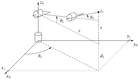
Figure 5.4 First three joints of an elbow manipulator.
provided xc and yc are not both zero.
If both xc and yc are zero, as shown in Figure 5.5, the configuration is singular as before and θ1 may take on any value.

Figure 5.5 Singular configuration for an elbow manipulator in which the wrist center lies on the z0 axis.
If there is an offset d ≠ 0 as shown in Figure 5.6 then the wrist center cannot intersect z0. In this case, depending on how the DH parameters have been assigned, we will have d2 = d or d3 = d, and there will, in general, be only two solutions for θ1.
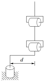
Figure 5.6 Elbow manipulator with shoulder offset.
These correspond to the so-called left arm and right arm configurations as shown in Figures 5.7.
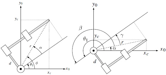
Figure 5.7 Left arm (left) and right arm (right) configurations for an elbow manipulator with an offset.
For the left arm configuration in Figure 5.7 we see geometrically that
in which

The second solution, given by the right arm configuration in Figure 5.7 is given by
To see this, note that

which together imply that
since cos (θ + π) = −cos (θ) and sin (θ + π) = −sin (θ).
To find the angles θ2, θ3 for the elbow manipulator given θ1, we consider the plane formed by the second and third links as shown in Figure 5.8. Since the motion of second and third links is planar, the solution is analogous to that of the two-link manipulator of Chapter 1. As in our previous derivation (cf. Equations (1.10) and (1.11)), we can apply the law of cosines to obtain

since r2 = x2c + yc2 − d2 and s = zc − d1. Hence, θ3 is given by
The two solutions for θ3 correspond to the elbow down position and elbow up position, respectively. Similarly θ2 is given as

Figure 5.8 Projecting onto the plane formed by links 2 and 3.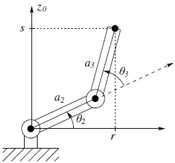
An example of an elbow manipulator with offsets is the PUMA shown in Figure 5.9. There are four solutions to the inverse position kinematics as shown. These correspond to the situations left arm–elbow up, left arm–elbow down, right arm–elbow up and right arm–elbow down. We will see that there are two solutions for the wrist orientation thus giving a total of eight solutions of the inverse kinematics for the PUMA manipulator.
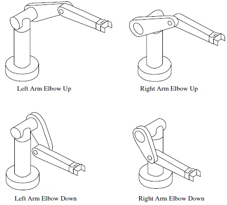
Figure 5.9 Four solutions of the inverse position kinematics for the PUMA manipulator.
5.4 Inverse Orientation
In the previous section we used a geometric approach to solve the inverse position problem. This gives the values of the first three joint variables corresponding to a given position of the wrist center. The inverse orientation problem is now one of finding the values of the final three joint variables corresponding to a given orientation with respect to the frame o3x3y3z3. For a spherical wrist, this can be interpreted as the problem of finding a set of Euler angles corresponding to a given rotation matrix ![]() . Recall that Equation (3.15) shows that the rotation matrix obtained for the spherical wrist has the same form as the rotation matrix for the Euler transformation given in Equation (2.27). Therefore, we can use the method developed in Section 2.5.1 to solve for the three joint angles of the spherical wrist. In particular, we solve for the three Euler angles, ϕ, θ, ψ, using Equations (2.29)–(2.34), and then use the mapping
. Recall that Equation (3.15) shows that the rotation matrix obtained for the spherical wrist has the same form as the rotation matrix for the Euler transformation given in Equation (2.27). Therefore, we can use the method developed in Section 2.5.1 to solve for the three joint angles of the spherical wrist. In particular, we solve for the three Euler angles, ϕ, θ, ψ, using Equations (2.29)–(2.34), and then use the mapping
Example 5.2. (Articulated Manipulator with Spherical Wrist).
The DH parameters for the frame assignment shown in Figure 5.4 are summarized in Table 5.1. Multiplying the corresponding Ai matrices gives the matrix ![]() for the articulated or elbow manipulator as
for the articulated or elbow manipulator as

The matrix ![]() is the upper left 3 × 3 submatrix of the matrix product A4A5A6 given by
is the upper left 3 × 3 submatrix of the matrix product A4A5A6 given by

The equation to be solved for the final three variables is therefore
and the Euler angle solution can be applied to this equation. For example, the three equations given by the third column in the above matrix equation are given by
Hence, if both of Equations (5.30) and (5.31) are not zero, we obtain θ5 from Equations (2.29) and (2.30) as
If the positive square root is chosen in Equation (5.33), then θ4 and θ6 are given by Equations (2.31) and (2.32), respectively, as
The other solutions are obtained analogously. If s5 = 0, then joint axes z3 and z5 are collinear. This is a singular configuration and only the sum θ4 + θ6 can be determined. One solution is to choose θ4 arbitrarily and then determine θ6 using Equation (2.36) or (2.38).
Example 5.3. (Elbow Manipulator — Complete Solution).
To summarize the geometric approach for solving the inverse kinematics equations, we give here one solution to the inverse kinematics of the six degree-of-freedom elbow manipulator shown in Figure 5.4, which has no joint offsets and a spherical wrist.
Given

then with
a set of DH joint variables is given by


The other possible solutions are left as an exercise (Problem 5–10).
Example 5.4. (SCARA Manipulator).
As another example, consider the SCARA manipulator illustrated in Figure 5.10, with forward kinematics defined by ![]() from Equation (3.24). The inverse kinematics solution is then given as the set of solutions of the equation
from Equation (3.24). The inverse kinematics solution is then given as the set of solutions of the equation

We first note that, since the SCARA has only four degrees of freedom, not every possible H from SE(3) allows a solution of Equation (5.46). In fact we can easily see that there is no solution of Equation (5.46) unless ![]() is of the form
is of the form

and if this is the case, the sum θ1 + θ2 − θ4 is determined by
Projecting the manipulator configuration onto the x0 − y0 plane yields the geometry shown in Figure 5.10. Using the law of cosines

and
The value for θ1 is then obtained as
We may now determine θ4 from Equation (5.48) as
Finally d3 is given as
Figure 5.10 First three joints of a SCARA manipulator. Table 5.1 DH parameters for the articulated manipulator of Figure 5.4.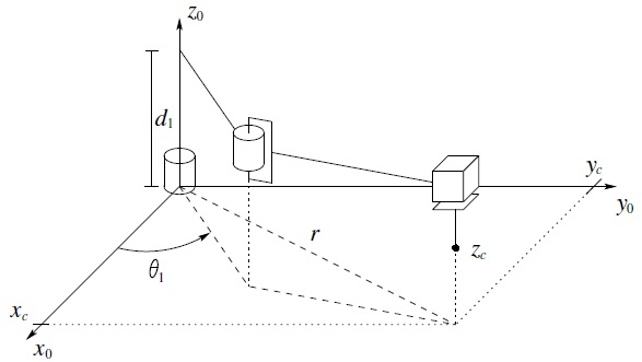
Link
ai
αi
di
θi
1
0
90
d1
θ1
2
a2
0
0
θ2
3
a3
0
0
θ3
5.5 Numerical Inverse Kinematics
For the manipulators considered in the previous sections we derived closed-form solutions for the inverse kinematics. In this section, we consider iterative, numerical algorithms for the computation of the inverse kinematics. Numerical methods are increasingly popular due to the availability of high-performance computation and the advent of open-source software. In addition, in cases where closed-form solutions do not exist, or if the manipulator is redundant, a recourse to numerical methods may be the better option.
Let ![]() be a vector of Cartesian coordinates. For example, xd could represent the wrist center point (m = 3) or the end-effector position and orientation using a minimal representation for the end-effector orientation (m = 6). The forward kinematics for an n-link manipulator, in this case, is a function
be a vector of Cartesian coordinates. For example, xd could represent the wrist center point (m = 3) or the end-effector position and orientation using a minimal representation for the end-effector orientation (m = 6). The forward kinematics for an n-link manipulator, in this case, is a function ![]() . If we set
. If we set
then a solution to the inverse kinematics is a configuration qd satisfying G(qd) = xd − f(qd) = 0. Below we will give details of the most common algorithms to iteratively solve for qd given xd; the first based on the Jacobian inverse, which is similar to the Newton–Raphson method for root finding, and the second is based on the Jacobian transpose and is derived as a gradient search algorithm.
With xd given as a desired robot configuration, we expand the forward kinematics function f(q) in a Taylor series about a configuration qd, where xd = f(qd) to obtain
where we take J = Ja(q) as the analytic Jacobian in Equation (4.83). Neglecting the higher order terms (h.o.t.), we have
assuming that the Jacobian is square and invertible. To find a solution for qd, we begin with an initial guess, q0, and form a sequence of successive estimates, q0, q1, q2, …, as
Note that we have introduced a step size, αk > 0, into the equation, which can be adjusted to aid convergence. The step size αk may be chosen as a constant or as a function of k, a scalar or as a diagonal matrix, the last in order to scale each component of the configuration separately.
Remark 5.1.
Since Equation (5.57) is based on a first-order approximation of the inverse kinematics, only local convergence can be expected. Also, since there are generally multiple solutions to the inverse kinematics, the particular configuration that results from running the algorithm is dependent on the initial guess.
Figure (5.11) shows the results obtained for a two-link, planar RR manipulator. The algorithm converges to within 10− 4 of the exact solution after 10 iterations with the given parameters.
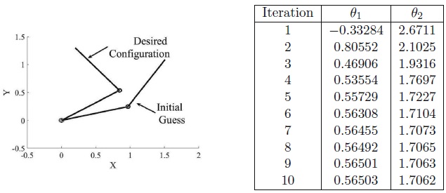
Figure 5.11 Inverse kinematics solution using the Jacobian inverse. Desired end-effector coordinates are xd = (0.2, 1.3). The joint variables corresponding to xd are θ1 = 0.5650, θ2 = 1.7062. The initial guess is θ1 = 0.25, θ2 = 0.75. The step size α was chosen as 0.75.
If the Jacobian is not square or not invertible, then one may use the pseudoinverse J† = J†a in place of J− 1a. For m ⩽ n, we defined the right pseudoinverse in Appendix B as J† = JT(JJT)− 1. In this case, we can define the update rule for qk as
The second method that we outline is based on the Jacobian transpose JT(q) instead of the Jacobian inverse. To begin, we define an optimization problem
where, as above, xd is the desired configuration and f(q) is the forward kinematics map. The gradient of the above cost function F(q) is given by
A gradient descent algorithm to minimize F(q) (see Appendix D) is then
where, again, αk > 0 is the step size.
Remark 5.2.
An advantage of this method is that the Jacobian transpose is easier to compute than the Jacobian inverse and does not suffer from configuration singularities. In general, however, the convergence, in terms of number of iterations, may be slower with this method.
Figure 5.12 shows the response for the two-link RR manipulator for the same desired configuration and initial guess as in Figure 5.11. In this case, the algorithm converges after 30 iterations.
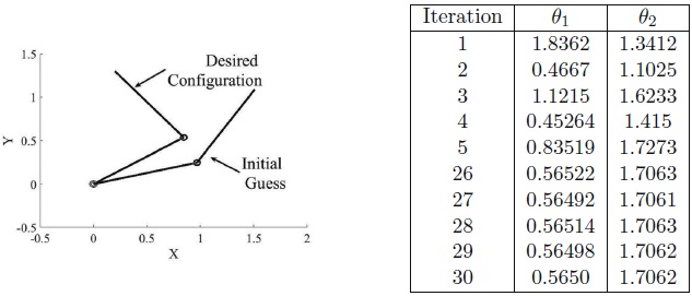
Figure 5.12 Inverse kinematics solution using the Jacobian transpose. Desired end-effector coordinates are xd = (0.2, 1.3). The joint variables corresponding to xd are θ1 = 0.5650, θ2 = 1.7062. The initial guess is θ1 = 0.25, θ2 = 0.75. The step size α was chosen as 0.75.
5.6 Chapter Summary
This DH convention defines the forward kinematics equations for a manipulator, i.e., the mapping from joint variables to end effector position and orientation. To control a manipulator, it is necessary to solve the inverse problem, i.e., given a position and orientation for the end effector, solve for the corresponding set of joint variables.
In this chapter we considered the special case of manipulators for which kinematic decoupling can be used (e.g., a manipulator with a spherical wrist). For this class of manipulators the determination of the inverse kinematics can be summarized by the following algorithm.
-
Step 1: Find q1, q2, q3 such that the wrist center
 has coordinates given by
(5.63)
-
Step 2:
Using the joint variables determined in Step 1, evaluate
 .
. -
Step 3: Find a set of Euler angles corresponding to the rotation matrix
(5.64)
We demonstrated a geometric approach for Step 1. In particular, to solve for joint variable qi, we project the manipulator (including the wrist center) onto the xi − 1 − yi − 1 plane and use trigonometry to find qi.
We also discuss numerical methods for computing the inverse kinematics using the inverse Jacobian and the Jacobian transpose. The Jacobian inverse kinematics algorithm takes the form
The Jacobian transpose inverse kinematics algorithm takes the form
Problems
- Given a desired position of the end effector, how many solutions are there to the inverse kinematics of the three-link planar arm shown in Figure 5.13? If the orientation of the end effector is also specified, how many solutions are there? Use any method in this chapter to characterize the inverse kinematics.
- Repeat Problem 5–1 for the three-link planar arm with prismatic joint of Figure 5.14.
- Solve the inverse position kinematics for the cylindrical manipulator of Figure 5.15.
- Solve the inverse position kinematics for the Cartesian manipulator of Figure 5.16.
- Add a spherical wrist to the three-link cylindrical arm of Problem 5–3 and write the complete inverse kinematics solution.
- Add a spherical wrist to the Cartesian manipulator of Problem 5–4 and write the complete inverse kinematics solution.
- Write a computer program to compute the inverse kinematic equations for the elbow manipulator using Equations (5.40)–(5.45). Include procedures for identifying singular configurations and choosing a particular solution when the configuration is not singular. Test your routine for various special cases, including singular configurations.
- The Stanford manipulator of Example 3.3.5 has a spherical wrist. Given a desired position
 and orientation
  of the end effector,
- Compute the desired coordinates of the wrist center
 .
. - Solve the inverse position kinematics, that is, find values of the first three joint variables that will place the wrist center at
 . Is the solution unique? How many solutions did you find?
 - Compute the rotation matrix
 . Solve the inverse orientation problem for this manipulator by finding a set of Euler angles corresponding to
  given by Equation (5.28).
- Compute the desired coordinates of the wrist center
- Repeat Problem 5–8 for the PUMA 260 manipulator of Problem 5–9, which also has a spherical wrist. How many total solutions did you find?
- Find all other solutions to the inverse kinematics of the elbow manipulator of Section 5.3.2.
- Modify the solutions θ1 and θ2 for the spherical manipulator given by Equations (5.15) and (5.16) for the case of a shoulder offset.

Figure 5.13 Three-link planar robot with revolute joints.
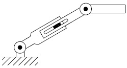
Figure 5.14 Three-link planar robot with prismatic joint.
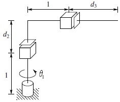
Figure 5.15 Cylindrical configuration.

Figure 5.16 Cartesian configuration.
Notes and References
The problem of inverse kinematics is classical and predates robotics by several hundred years. Consequently there is an extensive literature dealing with inverse kinematics within and without the robotics communities. An early fundamental result in robotics was the work of Pieper [137], who showed that any 6 DOF robot with at least three consecutive joint axes intersecting at a common point has a closed-form solution to the inverse kinematics. This property of robot kinematics is, in fact, the main reason for the importance of the spherical wrist. The approach that we use here of partitioning the inverse kinematics into inverse position and inverse orientation in the case of a spherical wrist is due to Hollerbach and Gideon [65]. We showed that the PUMA robot has 8 distinct inverse kinematic solutions. Primrose [139] gave an explicit upper bound of 16 for the number of inverse kinematic solutions for a general 6 DOF manipulator. This is a hard bound as shown by Manseur and Doty [108], who gave an example of a robot with 16 solutions. Although we do not treat the kinematics of parallel robots in this text, it turns out that the inverse kinematics problem for parallel robots is easier than it is for serial-link robots [68]. Numerical solutions to the inverse kinematics problem is treated in several sources, for example, [176] and [54]. Other good references for inverse kinematics of manipulators are, for example, [7], [92], [93], [135], [148], [119], and [105].
