
Chapter 8
Domain 6: Networks and Communications
An organization's data and information flow through and between a large number of network devices. These devices may be hardwired within the organization's premises or interconnected through the Internet. Users may connect to the network through a hardwired connection from their host workstation or through the use of wireless connections.
As an SSCP, is important for you to understand all of the communication paths within the network, whether wired or wireless, and the different types of signaling protocols that are used to control devices or inform other users of the type of information that is being transmitted.
In this domain, we will investigate various theories and concepts used in modern networks and look at the devices that interconnect users to each other as well as to data sources. With the advent of voice and multimedia over digital networks, you need to understand the importance of prioritizing the transmission of information, which is known as traffic shaping. Also, intruders can take advantage of your networks, so you must implement detection measures as well as appropriate controls to mitigate the damage they might do.
Network Models
Networks are founded on the principle of device-to-device telecommunications. No longer are computers stand-alone devices that work in total isolation. It is only natural that a user must connect to another user or to a remote data source. Originally, computer systems were only required to communicate with other devices within their local premises, thus the term local area network (LAN). In the past, if users or systems were required to connect to customers or clients to exchange information, they used a dedicated circuit provided by the telephone company and an agreed-upon information format such as electronic data interchange (EDI).
Today, communication over the Internet is so common that little regard or concern is given to the methods required behind the scenes to make it happen. Yet a number of different signaling and communication techniques are required between the two entities in order to facilitate basic communications.
TCP/IP and OSI Reference Models
Data encapsulation is the foundation of both the TCP/IP and OSI models. In essence, when a document is to be sent from one user to another, the entire document must be reduced into bite-sized chunks that can ultimately be transmitted over wires. To accomplish, this the data must proceed through a number of permutations, which establishes not only the communication path between the two host computers but also the agreed-upon signaling technology using copper wires, fiber optics, or wireless radio systems.
OSI Reference Model
The Open Systems Interconnection (OSI) model is a conceptual model that characterizes and standardizes the internal functions of a communication system by segmenting it into layers. The OSI model is not a protocol; it is a model used for understanding and designing a communication architecture that allows any two systems to communicate regardless of the underlying hardware or software infrastructure.
The model consists of seven logical layers, numbered 1 through 7. A layer responds to or is served by the layer above it and similarly serves the layer below it. For example, one layer establishes a connection between two host machines and accepts the data to be transmitted from the layers above it. Once the connection is established by this layer, the layer below it is responsible for actually sending and receiving the packets.
Figure 8.1 shows all seven layers and illustrates the relationships between them.

Figure 8.1 The Open Systems Interconnection model
The OSI model groups data encapsulation functions into seven layers of logical progression. Each layer communicates only with the layer above it and the layer below as the information flows through the model. For instance, every layer serves a specific purpose. Each layer will add an appropriate header to the data, which will be interpreted at the exact same layer on the receiving host.
It is important to understand the operation of this model. It's only natural to understand that the transmitted data between two machines must flow over some sort of wire or media that connects the two computers. The actual physical connection is illustrated at the bottom of Figure 8.1. The original application data to be exchanged is illustrated between the software applications at the top of the diagram. This is the same data that might be saved to a USB drive as a data file and then reopened by the same application on a different computer.
To transmit the data over a wire connecting two computers, it is important to accomplish several functions, such as defining the type of data to be transmitted, beginning and maintaining the connection, checking for errors during the communication, determining the logical and physical addresses of the machine to receive the information, and finally, converting the data into electrical pulses on a copper wire, fiber-optic cable, or Wi-Fi radio signal.
All of this is accomplished at different layers of the OSI model. At each layer, a set of instructions is appended to the data that informs the other computer what to do and the operations to be performed at that specific layer. This information is embedded in a header created at each layer of the model and is attached in layer order to the data. Upon receiving the data, with all of the headers attached, the receiving computer processes the data up the OSI model, taking the appropriate actions at each layer and then stripping off that layer's header. Ultimately, the receiving computer, having completely processed the transmitted data, passes the data to the appropriate application.
TCP/IP Reference Model
The U.S. Department of Defense, through the Defense Advanced Research Projects Agency (DARPA), created the TCP/IP model. The TCP/IP model is usually depicted with four layers that include Application layer, Transport layer, Internet layer, and Network access layer. It is a much simpler model and predates the OSI reference model. Figure 8.2 illustrates the mapping between the seven-layer OSI model and the four-layer TCP/IP model.

Figure 8.2 The OSI model mapped to the TCP/IP model
OSI vs. TCP/IP Models
When discussing networking, most refer to the seven-layer OSI model—long considered the foundation for how networking protocols should operate. This model is the most commonly used model, and the division between layers is well defined.
TCP/IP precedes the creation of the OSI model. While it carries out the same operations, it does so with four layers instead of seven. Those four layers are discussed in the following section, but it is important to know that while TCP/IP is the most commonly used protocol suite, OSI is the most commonly referenced networking model.
OSI Model Layer 1: The Physical Layer
All of the physical connections to the network are found at this layer. It is at this layer where 1s (ones) and 0s (zeros) become a voltage or flash of light or maybe even a modulated radio signal. All of the cables, connectors, interface cards, network taps, hubs, fiber-optic cables, and repeaters operate at this level. The physical layer is where we connect everything together using wires, radio signals, or fiber optics. All data at the Physical layer is represented by bits (1s and 0s).
There are many different types of media used for data transmissions, as explained in the following sections.
Wireless Radio Transmissions
Wireless radio transmissions utilize radio receivers and transmitters set at a certain frequency to both transmit and receive data communications. Because of the limited bandwidth available, several radio frequency modulation techniques are used to place more data within a limited bandwidth. A layer 1 wireless device would take the form of a wireless access point or a transceiver embedded in the circuitry of the cell phone. For instance, a cellular telephone may have two or more MAC addresses, one for each radio, such as the cellular radio and the Bluetooth radio.
Fiber-Optic Transmissions
Fiber-optic data transmission offers some of the highest bandwidth transmission rates and is least likely to be tapped into by an intruder. Fiber cable comes in various specifications:
- Single-Mode This type of fiber-optic cable has a small-diameter glass core that decreases the number of light reflections. This allows for greater transmission distances, up to 80 kilometers (km). Single-mode fiber-optic cable is much more expensive than any other cable and is used primarily in long-distance-transmission backbone environments. The standard color coding of the outer jacket for single-mode fiber-optic cable is yellow.
- Multimode This type of fiber-optic cable uses a much larger-diameter core than single mode. Light is allowed to refract and reflect, subsequently increasing the light degradation of signal loss. Multimode fiber-optic cable is used for shorter distances, up to approximately 400 meters (m). This cable is ideal for use in a local facility or building. The standard color coding of the outer jacket for multimode optical fiber cable is orange.
- Plastic Optical Fiber This type of fiber-optic cable uses a plastic core that allows for larger-diameter fibers. Plastic optical fiber is less capable of transmitting light over distances; therefore, this cable is restricted to 100 m or less but is the least expensive of any optical transmission cable.
Fiber-optic cable functions as a light conduit guiding the light introduced by a laser or light emitting diode (LED) light source at one end to a light-sensitive receiver at the other end. The light beams may be modulated to increase the number of communication channels on each fiber.
Fiber optics utilize a principle known as total internal reflection in which light is reflected back into the cable rather than exiting the glass. Using this technique, light beams in the form of modulated pulses transmit information down fiber lines. To minimize the loss of light and reduction of cable length, the fiber-optic cables must be made of very pure silica glass. Fiber-optic cables may be made of other types of glass based upon the shorter wavelength of ultraviolet or longer wavelength of infrared lasers.
Fiber-optic cable is subject to loss of lumen strength primarily through dispersion, which is the scattering of the light beam. For longer-length transmissions, repeaters may be utilized to strengthen the beam of light and to refresh the signal. A type of semi-flexible plastic conduit or subduct that is designed to both protect the bundle of fiber-optic cables from environmental elements and provide low friction through which to pull easily breakable, low-tensile-strength fiber-optic cables is called an innerduct. Innerduct interior tube design may include smooth walls, corrugated walls, and ridged walls to promote the lowest coefficient of friction when delicate fiber-optic cable is pulled.
Copper Cable/Twisted-Pair
Copper cable is the most common method of communicating signals from one point to another. Sometimes just referred to as “copper,” twisted-pair wire has always been the transmission medium of choice. Easy to use and inexpensive, it also affords the easiest transmission method.
Copper cable is subject to electromagnetic interference from nearby radiating sources, which include lights, fans, motors, and other cables. When the cable is twisted, effective electromagnetic interference is weakened as well as the emissions from the cable itself.
Various types of copper cables may be used within a network environment:
- Twisted Pair This cable features pairs of twisted copper wires, referred to as twisted-pair cable TP, that are encased in a plastic outer casing. It's sometimes referred to as plenum wire because this cable is normally run within the plenum area above the ceiling or inside walls. The plastic casing in plenum wire is both resistant to burning and resistant to emitting toxic fumes during a fire.
- Unshielded Twisted-Pair This cable features numerous individual copper cable strands twisted together. In most network situations, these strands are encased in a plastic outer insulation. Unshielded twisted-pair cable is referred to as UTP.
- Shielded Twisted-Pair This type of cable, generically referred to as shielded twisted-pair cable (STP), utilizes a common ground shield encasing the twisted strands.
- Screened Shielded Twisted-Pair This type of cable features shielding encasing each of the twisted pairs as well as the outer bundle of twisted pairs. This eliminates EMI between the twisted-pair sets and prevents EMI from entering or exiting the cable bundle.
Screened shielded twisted-pair is a cable description that specifies both an internal twisted-pair shielding as well as an overall cable bundle shield. This shielding may take the form of either metallic foil or metallic wire braiding. Using this nomenclature, F stands for foil-based shields, while S refers to metallic braided shields. For instance, F/FTP indicates a foil shield encasing the wire pairs as well as a foil shield encasing the wire bundle. The S/FTP designation would refer to a foil shield encasing the wire pairs with a braided metallic shield encasing the wire bundle.
This technique of shielding offers greater isolation from external electromagnetic interference signals and from internal signals being emitted between conductors. Shielded twisted-pair cable always utilizes a type of grounded metal shielding to encase the twisted-pair copper cables. There are three types of shielded twisted-pair cable for high-bandwidth applications such as CAT6a, CAT7, and CAT8 cables.
- STP Designates shielded twisted-pair, which is a twisted-pair cable with braided metallic shielding that encases all of the twisted pairs.
- F/UTP Designates a twisted-pair cable with foil shielding that encases all of the twisted pairs.
- F/FTP and S/FTP Designates a fully shielded twisted-pair cable where internal twisted pairs are individually shielded and the entire cable bundle is encased by an external shield. The F designates foil, while the S indicates a braided shield.
Figure 8.3 depicts various categories of shielded twisted pair cable and the relative transmission speeds.
-

Figure 8.3 Categories of twisted-pair cable
Coaxial Cable
Coaxial cable, or coax, is constructed as a large copper central conductor encased in a nonconductive dielectric material that is then encased within a braided copper shield. The entire assembly is then covered with a plastic casing. Coaxial cable is much less resistant to interference and cross talk. Also, due to the size of the central conductor, coaxial cable is capable of handling much greater current loads and is therefore ideal for radio antenna lead cables. Coaxial cable is much more expensive than twisted pair and requires a much wider bend radius.
Plenum Cable
Plenum cable is a specifically jacketed cable with a fire retardant plastic jacket. Most local building codes adopted cable specifications for any cabling or wires that are routed through the plenum spaces within a building. Plenum spaces include areas above all ceilings, interior walls, riser areas, and control cabinets and closets. Plenum cables not only offer fire resistance, they are constructed of low-smoke and low-toxic-fume-emitting polymers such as polyvinyl chloride (PVC).
Data Transmission Methods
Data may be transmitted on media using two different methods:
- Baseband Data transmitted using baseband transmission occupies the entire frequency range of the media. No other data is transmitted concurrently.
- Broadband Broadband transmission, which is popular with cable television and networking providers, is used to multiplex a very large number of signals on a single media.
OSI Model Layer 2: The Data Link Layer
Layer 2 addresses traffic to a physical link address. Every network interface card contains a Media Access Control (MAC) address. A MAC address is the physical address of the directly connected device and consists of a manufacturer's identification as well as a unique number identifying the device.
Layer 2 switches, sometimes referred to as L2 switches, operate at this layer. As traffic comes into a switch on a specific switch port, the switch creates a map table identifying the device with the MAC address in the specific switch port. When data is received by the switch and is destined for a specific MAC address, it is forwarded out that specific port. Digital information received or sent at the Data Link layer is formatted as frames. The Data Link layer is concerned with directing data to the next physically connected device.
OSI Model Layer 3: The Network Layer
The Network layer determines the routing of data across a network utilizing a logical address referred to as an Internet Protocol (IP) address. An IP address such as 192.168.40.10 represents the logical address of node 10 on network number 40. Through the use of the Dynamic Host Configuration Protocol (DHCP), a different logical address is given to a host at each logon.
The Network layer moves data along the network between two hosts that are not physically connected. Layer 3 devices such as routers read the destination layer 3 IP address and make use of a routing table on the router to determine the next device in the network to send the packet.
OSI Model Layer 4: The Transport Layer
The Transport layer moves data packaged in segments. This layer provides end-to-end and reliable communications services and includes error detection and recovery methods. Two primary protocols are utilized at this layer.
- User Datagram Protocol The User Datagram Protocol (UDP) is referred to as a connectionless protocol. Connectionless refers to sending information without first verifying that the connection exists between the hosts. The sending host has no expectation of receiving a reply or confirmation that the data has been received. Should an error occur or should data not be received, it is incumbent upon the receiving host to request a retransmission. UDP is ideal for transmission of voice or media.
- Transmission Control Protocol The Transmission Control Protocol (TCP) is referred to as connection-oriented because it provides guaranteed and reliable communication between devices on the network. TCP requires that the receiving host acknowledge every packet that it receives. Packets may be received out of order and may be re-sequenced by the receiving host.
Figure 8.4 illustrates the three-way handshake used to begin a TCP session. The first step of the handshake is where the host sends the server a packet with the SYN, or synchronize, flag turned on or “set.” The server responds with a packet that has both the acknowledgment ACK and SYN flags set. Finally, the host responds with a packet that has the ACK flag set. At this point, the TCP session has been established.

Figure 8.4 TCP three-way handshake
Other protocols that require guaranteed delivery may be paired up with TCP. Probably the most famous pairing is TCP/IP, where the IP address provides the packet routing information and TCP provides the guaranteed delivery and request for resend for error correction.
OSI Model Layer 5: The Session Layer
The Session layer establishes and maintains sessions between peer hosts. A session is similar to a connected phone line between two parties. The two parties in this case are logically connected without regard to the type or nature of information that is transferred between them.
OSI Model Layer 6: The Presentation Layer
The Presentation layer is sometimes referred to as the translation layer because of the change in data at this layer. At this layer, data being sent from a host application may be required to be translated or changed before being presented to the receiving host application. For instance, an IBM application may provide data which is formatted using the Extended Binary Coded Decimal Interchange Code (EBCDIC). The receiving application may require the data to be presented to it in American Standard Code for Information Interchange (ASCII) code. The Presentation layer also maintains the capability of providing some encryption and decryption as well as data compression and decompression.
OSI Model Layer 7: The Application Layer
The Application layer provides a variety of services so that the application data can be transmitted across the network. This layer may also provide access control methodology, such as identification, authentication, and availability of remote applications; hashing for integrity; and the checking of digital signatures.
Network Design Topographies
A network topology is the design, or the physical layout, of the network. In other words, it is the layout of wires, cables, fiber optics, routers, switches, and all of the servers and host machines.
The design of early networks preceded the availability of the basic networking component equipment such as routers and switches of today and even the use of Ethernet. Numerous challenges greeted the network engineers of yesterday. Wiring required a reduced-run length due to the attenuation or fading of the data signals. There was the problem of who had priority on the network to send data and what would happen if two hosts transmitted at the same time. These and many more problems led to some of the early network designs.
Network Topology Models
Network topology has changed through the years. The following five models depict the most popular layouts:
- Bus The bus topology was one of the earliest and most commonsense designs for local area network layout and design. The central bus wire featured terminators at each end, and computer hosts as well servers were connected to the central bus wire through what was known as “drops.” There were a couple of advantages to this system. Adding a node to the bus was very easy, and if an individual node failed, it would not affect other nodes on the central bus wire.
A disadvantage was that if the central bus wire failed, the entire network failed as well because the cable run lengths had to be short due to signal fading. Each of the drop cables connected to the central bus wire with a special connector. The connector not only reduced the amplitude of the signal, but if they were disconnected inappropriately, the entire network would fail. Figure 8.5 illustrates a common bus topology.

Figure 8.5 A bus topology
- Tree The tree topology is similar to several parallel bus structures, each containing networking items, one placed on top of the other. The top-level bus drops to a server. The server then connects below it to another bus, which contains hosts or workstations. This is a layered approach to a bus structure, but it still maintains the same problems as a bus topology. If the last centralized device fails, everything below it also fails. Figure 8.6 illustrates a tree topology.

Figure 8.6 A tree topology
- Ring The ring topology is an older technology predating Ethernet networks and was made popular by IBM. It provided a solution to the problem of who talks next. When a token was circulated around a closed loop ring, each node could determine exactly when they could transmit next. This was referred to as a deterministic system. Typically, token ring networks consisted of coaxial cable or fiber-optic cable. Because the entire ring is a single point of failure, later technology such as Fiber Distributed Data Interface (FDDI) provided redundancy by using two rings for failover. Ring topology has been almost totally eliminated and replaced by Ethernet technology. Figure 8.7 illustrates a typical ring topology.

Figure 8.7 A ring topology
- Mesh In a mesh topology, every node is connected to every other node. This provides great redundancy and speed, usually at a very large expense. Mesh topologies are used where speed and redundancy are required, such as with fault-tolerant devices, load distribution server clustering, and storage area networks (SANs). In the storage area network application, the mesh network is between the servers and the storage devices, which allows for great speed and redundancy. This type of mesh usually consists of fiber-optic cables and is sometimes referred to as a fiber fabric.
The number of connections required in a mesh network can be illustrated through the equation N * (N - 1) / 2, where N equals the number of devices. For instance, if there were 10 devices on the mesh network, the equation would be 10 * 9 / 2 = 45 connections. If 2 more devices were added to the network, the equation would be 12 * 11 / 2 = 66 connections. So as you can see, when just two additional devices were added, the number of connections jumped by 21. Figure 8.8 illustrates a mesh topology.

Figure 8.8 A mesh topology
- Star Present-day networks generally take the form of a star topology. In this type of layout design, each node is connected to a central device such as a switch or router. Although the use of a centralized connection devices inserts a single point of failure, the flexibility of this type of network design allows for shorter cable runs and ease of network deployment. Figure 8.9 illustrates a star topology.

Figure 8.9 A star topology
Network Connection Models
Various types of networks are required to transmit data across town or across the country. The design of these networks spans the period of wires hanging on telephone poles to today, when the very latest technologies are available.
- Circuit-Switched Networks Circuit-switched networks are created by physically connecting to endpoints through a series of wires and mechanical switches where the signal voltage generated at one endpoint is received by the other endpoint. A disadvantage of this early network communication was both lack of available bandwidth and poor line quality.
A typical example of a circuit-switched network was known as plain old telephone service (POTS). Telephone companies grappled with digital technology as they made every attempt to transmit data over relatively low-quality standard telephone lines. One of the outgrowths of this was Integrated Services Digital Network (ISDN), and other techniques were also used in the quest for higher speed and greater reliability. In these later data network offerings, carriers offered dedicated networks to clients and billed only for time of use.
- Packet-Switched Networks Typical of most wide area networks today, a packet-switched network makes use of a large number of devices with nondedicated connections. Information is subdivided into packets that feature an address of the ultimate destination. Devices such as routers use the destination address and forward the packet to the next router until the packet eventually arrives at its destination. Since the packet-switching network is dynamic and ever changing, packets within one conversation may take numerous routes. Because of this, packets may arrive out of order, and it is up to the receiving device to resequence the packets in the correct order.
- Virtual Circuit Networks Some organizations require high-bandwidth connections between offices, clients, or other endpoints. In such cases, they may contract with a carrier for a special type of data network.
- Permanent Virtual Circuit A permanent virtual circuit (PVC) is a connection between endpoints where the carrier configures the circuit routes to provide the requested speed and bandwidth through their equipment. This provisioning is usually accomplished when the permanent virtual circuit is initially contracted and when the dedicated hardware and contracted bandwidth is determined. Typically, once a permanent virtual circuit is established, it remains connected.
- Switched Virtual Circuit A switched virtual circuit (SVC) dynamically configures the circuit routes each time the circuit is used by the end user. A switched virtual circuit is less expensive and is billed for only time of use.
Media Access Models
Through the years network engineers have struggled with the concept of trying to get more users to communicate on a single piece of wire. Various techniques, some better than others, have been designed to eliminate congestion in an attempt to provide an orderly flow of data through a network.
- Carrier Sense Multiple Access Carrier sense multiple access (CSMA) is a media access control protocol used to communicate on the media such as a wire, fiber-optic cable, or modulated radio signal. Carrier sense refers to the fact that the device is listening to the media at all times. It is specifically listening for the transmission of other devices. Multiple access means that all of the devices on the wire or network are transmitted the same time. Of course, if they are, the transmitted data would be unrecognizable. This type of communication has no mediating controller and therefore is called contention-based access and nondeterministic. It is the least effective of any of the transmission protocols because none of the devices have any means of determining when to transmit data.
- Carrier Sense Multiple Access/Collision Detection Carrier sense multiple access/collision detection (CSMA/CD) is a media access control protocol used to communicate in an organized fashion on a type of media. As in CSMA, a device may begin transmitting at the same time another device transmits. When this happens, two frames will be transmitted simultaneously and a “collision” will occur. Each of the two devices will wait a random period of time and then retransmit. The random timer prohibits each of the two devices from immediately retransmitting and causing a collision once again. This is the most-often-used technique to reduce transmission contention on modern local area networks.
- Carrier Sense Multiple Access/Collision Avoidance Carrier sense multiple access/collision avoidance (CSMA/CA) is a media access control protocol used to announce that a device is wishing to transmit on the media. The device will transmit or broadcast a tone prior to transmission. The tone is referred to as a jamming signal and will be received by all other devices connected to the media. After waiting a brief interval to ensure that all other devices are aware of the device's desire to transmit, the device begins transmitting.
- Ethernet Ethernet is an IEEE 802.3 standard that supports a number of different media standards such as coaxial, fiber-optic, and shielded and unshielded twisted-pair cable. Ethernet speeds include 100 megabits per second (Mbit/s) to 1,000 Mbit/s over both unshielded twisted-pair and fiber-optic cables. Through the use of CSMA/CD, most collisions are dealt with on smaller networks or limited-broadcast domains. On larger networks, there may be major network media contention due to retransmission volume.
Ports and Protocols
Ports and protocols are utilized within both hosts and servers to facilitate the connection between received and transmitted information. A port is a special type of memory address to which an application or service on the system listens and transmits. This is its access to the outside world and method of receiving data.
Ports
Ports are special addresses in memory that allow communication between hosts and applications or services running on a host. A port number is added to the address from the originator, indicating which port to communicate with on a server. If a server has a port defined and available for use, it will send back a message accepting the request. A server is instructed to refuse to connect if the port isn't valid. The Internet Assigned Numbers Authority (IANA) has defined and maintains a list of ports called well-known ports.
Ports may also prove to be a source of security weakness. An intruder may perform a port scan to determine which ports are open and may be penetrated to gain access into a system. Therefore, any unused ports should be blocked by a firewall to reduce the possibility of intrusion.
Well-known ports are those ports that have been assigned to specific software applications, services, and protocols. For instance, port 80 is the common port for all Internet traffic. Ports are identified by the specific communication method they use. TCP ports expect to set up a three-way handshake, while UDP ports will transmit all of the information without expecting a confirmation of receipt. Table 8.1 lists well-known TCP ports, and Table 8.2 lists well-known UDP ports. Ports with an asterisk are important to know.
Table 8.1 Well-known TCP ports
| TCP Port Number | Service |
| 20 | FTP (data channel) |
| *21 | FTP (control channel) |
| *22 | SSH and SCP |
| 23 | Telnet |
| *25 | SMTP |
| *80 | HTTP |
| *110 | POP3 |
| 119 | NNTP |
| *143 | IMAP |
| 389 | LDAP |
| *443 | HTTPS |
Table 8.2 Well-known UDP ports
| UDP Port Number | Service |
| *22 | SSH and SCP |
| 49 | TACACS |
| *53 | DNS |
| 69 | TFTP |
| *80 | HTTP |
| *143 | IMAP |
| 161 | SNMP |
| 389 | LDAP |
| 989 | FTPS (data channel) |
| 990 | FTPS (control channel) |
There are total of 65,536 ports available. Note that there is a port number 0 (zero), which makes the range of port numbers 0 to 65,535. These ports are divided into three primary groups:
- Well Known Ports: Ports 0–1023 Well-known ports are ports that are assigned and matched to specific protocols. The port number is embedded in a packet destined for a host or server machine.
- Registered Ports: 1024–49151 Registered ports are ports that are reserved to be used by third-party applications, services, and networking devices to communicate between machines.
- Dynamic, or Private, Ports: 49152–65535 The upper layer of the port range may be used by applications that begin a conversation at a port with a lower number and then switch the conversation to a port with a higher number. Using this technique releases the lower port to respond to additional communication requests.
Common Protocols
There are hundreds of protocols. The difficulty is in determining how each protocol is used and whether it is secure. The following list details a number of common protocols.
- File Transfer Protocol File Transfer Protocol (FTP) is an older interconnect protocol that allows connections between machines for file uploads and downloads. FTP is among the original protocols developed for the Internet. Ports 20 and 21 are used by default by FTP to transfer information between hosts and the Internet. Due to its design, FTP is insecure.
- Simple Mail Transfer Protocol Simple Mail Transfer Protocol (SMTP) is the standard protocol for email communications. SMTP involves the use of email clients and servers to transmit messages. The default port is 25.
- Domain Name System Domain Name System (DNS) allows hosts to resolve hostnames to an Internet Protocol (IP) address. For instance, DNS would convert a fully qualified domain name into an IP address. The default port used by the domain name system when sending name queries for this service is 53.
- Simple Network Management Protocol Simple Network Management Protocol (SNMP) is a management tool that allows network devices to send selected parameter data to a management console. A software client runs on the network device and captures various parameters and performance data at the request of a central administrator. Most routers, bridges, and other network appliances can be monitored using SNMP.
- Post Office Protocol Post Office Protocol (POP) is a protocol used in many email systems. It is a standard communications interface in many email servers. Post Office Protocol is used for receiving email. The default port for version 3 (POP3) is 110. In its place, many systems now use the Internet Message Access Protocol (IMAP) to download email messages from a storage location upon request. IMAP is assigned to port 143.
- Telnet Telnet is a legacy protocol and performs as an interactive terminal emulation protocol. It allows a remote user to maintain an interactive session with a Telnet server. The Telnet session will appear to the client as if it were a local session.
- Address Resolution Protocol Address Resolution Protocol (ARP) provides a process for resolving IP addresses into Data Link layer MAC hardware addresses. ARP resolves an IP address to a Media Access Control (MAC) address. MAC addresses are used to identify hardware network devices and are assigned to the network interface card (NIC).
- Internet Control Message Protocol Internet Control Message Protocol (ICMP) provides reporting and maintenance functionality. ICMP includes a number of communication information commands, such as
pingto test connectivity andtracerouteto return the route used by packets to a destination. Routers and other network devices can report path information between hosts using ICMP.
Maintaining the security of ports is very important. One of the common procedures in hardening a system is to close unused ports and remove unused protocols. Closing unused ports is generally accomplished by blocking the port on a firewall. It is important to consider blocking not only popular specifically named ports but also a large range of ports that may be exploited by an intruder.
Converged Network Communications
The convergence of network communications involves the combination of media transmission, including Voice over Internet Protocol (VoIP) as well as television, radio, and nontraditional data content that will be generated by the Internet of Things (IoT). The basic type of network convergence is the combination of media files and data files and the physical connection across differing platforms and networks, which allows several types of networks to connect with each other within certain common standards and protocols.
Convergence involves new ways of communicating over a digital medium involving both existing and emerging content suppliers. Digital technology now allows both traditional and new communication services—whether voice, data, sound, or pictures—to be provided over many different types of digital transmission mediums that traditionally required separate networks. For instance, although broadcast television was an essential provider of both entertainment and news content through most of the 20th century, fewer and fewer homes will be equipped with broadcast receiver equipment. Television programming will soon evolve onto a digital communication medium where content may be provided across multiple platforms. Similarly, there has been a major decline within the newspaper industry as the majority of individuals are now seeking their news content digitally on multi-platform devices rather than reading print on paper.
Generational differences in the use of digital assets will drive the marketplace away from what was traditional mid-20th-century communication mediums such as wired telephones within the house, newspapers in the front yard, and a limited number of local broadcast television stations into a digitized world of information. Younger generations eagerly adopt new technology that offers the freedom of multi-platform, interactive information on demand.
Because the traditional communication methodology such as newspapers and broadcast media is no longer in demand, digital convergence will place all of the communication channels into a digital world. Whether at home, at the office, or in a classroom, the demand for convenience and entertainment will drive the marketplace into an expansive offering of digital services.
Network Monitoring and Control
Network monitoring and control is usually included in the job description of an SSCP. From monitoring the performance of devices to establish baselines and assure their continued security performance to monitoring network traffic to discover anomalies and possibly intruders, network monitoring and control provides an essential role in network security.
Continuous Monitoring
Continuous monitoring involves the policy, process, and technology used to detect risk issues within an organization's IT infrastructure. This monitoring may be in response to regulatory or contractual compliance mandates.
Continuous monitoring of network operations stems from a risk assessment program where it was required for financial transactions. During the financial transactions monitoring procedure, the disposition of all transactions is recorded and analyzed for risk and regulatory compliance.
The continuous monitoring of network operations is where security incident and event monitoring (SIEM) activities are maintained on a 24/7 basis. Logs must be maintained for specific time periods and analyzed as appropriate. Effectively, continuous monitoring requires that all users be monitored equally, that users be monitored from the moment they enter the physical or logical premises of an organization until they depart or disconnect, and that all activities of all types on any and all services and resources be tracked. This comprehensive approach to auditing, logging, and monitoring increases the likelihood of capturing evidence related to abuse or violations.
Network Monitors
Network monitoring devices are available with several different modes of operation, which include active and passive modes. Passive network monitors, otherwise called sniffers, were originally introduced to help troubleshoot network problems. Intrusion detection systems are also passive network monitoring devices.
A network monitoring system usually consists of a PC with a NIC (running in promiscuous mode) and monitoring or logging software. Promiscuous mode simply means that the network card is set in such a way that it accepts any packet that it sees on the network, even if that packet is not addressed to that network interface card.
The amount of information obtained from network traffic may be immense. Logical filtering to identify anomalies or items of interest must be undertaken due to the overwhelming amount of traffic.
Active network monitors, such as intrusion prevention systems, also monitor network traffic activity, but they are tuned to detect specific anomalies. In the event they discover traffic that should not be allowed on the network, an active monitor will take some predetermined action, such as dropping the packet or generating a firewall rule.
Managing Network Logs
Network logs are the lifeblood of a network monitoring operation. They can be set to record every event that happens on the network. This would create a large volume of information very quickly. There are several different types of logs, and the SSCP should be familiar each of them.
Event/Security Logs
Event logs are networking or system logs that record various events as they occur. Everything that happens on a network—an individual logging in, developing an application, accessing a database, and sending an email—can be recorded. When you combine the events caused by individuals with all of the events caused by applications accessing each other, the amount of event information can be huge.
Event logs is a broad category that includes some logs not relevant to security issues. But within that broad category are security and access logs that are clearly important to the security of the network. Microsoft Windows has a great amount of logging capability; the two most important logs for security purposes are listed here:
- Application Log This log contains various events logged in real time by applications, databases, or other programs. It is generated by many applications that will be recorded in the application log. This type of log is useful within an application such as SQL Server to determine problems within a database. An application log can be examined for evidence that an intruder has been attempting to compromise a database or application.
- Security Log The security log records events related to resource use, such as creating, opening, and deleting files or manipulating other objects. Among the many events the security log records, two of the most important are the successful and unsuccessful logon attempts by users. A security log can easily be fine-tuned so that a security administrator can audit events of interest.
Audit Logs
Audit logs offer crucial information about the actions and activities on an organization's network. Auditors that are internal to the organization review proper activities on servers and network devices while external auditors may be analyzing network operations for regulatory compliance.
The log files created by network services such as DNS need to be routinely examined. The DNS service, when running on Windows Server 2012 R2, for example, writes entries to the log file that can be examined using Event Viewer. Log size and overwrite options may be set by the operator for each security log object.
A firewall with event logging enabled will create log files the same as many other services. Since firewalls are extremely important to the network, administrators should regularly review the logs. Firewall logs may be generated in a central location or on the host's or client's firewall device.
Most antivirus programs also create log files that should be checked regularly by an administrator. The logs should verify not only that the antivirus program is running but also that the definition files being used are up to date and current. The administrator should pay attention to the viruses that are found and deleted/quarantined as well as any files that are being skipped.
Access Control Protocols and Standards
Every user must be authenticated when requesting entry into a computer network. As the number of network users increases, so does the complexity of the authentication mechanisms used to provide them with access to the network. Many users may be sitting at their desk or cubicle when logging into a computer network, but an ever-increasing number will be in a home office, at an airport, or at a client site when requesting access into the network. There are several techniques for both transporting information to a remote location and verifying the identity and authentication of the user.
Remote Network Access Control
Users wishing access to an enterprise network may be across the street, across town, or around the world. In any event, they are normally transmitting data through an untrusted network, such as the Internet. It is important to place controls on the network to mitigate the risk of data interception, corruption, and a variety of other attacks that might occur when data is transmitted and receive across this type of network.
A virtual private network (VPN) is a private network connection that is established through a public network. Creating a tunnel, or VPN, is a method of encapsulating restricted or private data so that it may not be read or intercepted when traversing the Internet. Encapsulation is the act of placing restricted data inside a larger packet and placing a special destination address on the packet so that it may be routed to the intended receiver.
A virtual private network provides information security through encryption and encapsulation over an otherwise unsecure environment. VPNs can be used to connect LANs together across the Internet or through other public networks. When a VPN is used, both ends appear to be connected to the same network. A VPN requires a VPN software package to be running on servers and workstations. Figure 8.10 illustrates a virtual private network connecting two different networks.

Figure 8.10 A virtual private network
Tunneling protocols are used to encapsulate other packets that are sent across public networks. Once the packets are received, the tunneling protocol is discarded, leaving the original information for the receiver.
The most common protocols used for tunneling are as follows:
- Point-to-Point Tunneling Protocol Point-to-Point Tunneling Protocol (PPTP) supports encapsulation in a single point-to-point environment. PPTP encapsulates and encrypts point-to-point protocol (PPP) packets. Although PPTP is a favorite protocol for network communications, one of its major weaknesses is that all channel negotiation is done in the clear. After the tunnel is created, the data is encrypted. Developed by Microsoft, PPTP is supported on most of the company's products. PPTP is assigned to port 1723 and uses TCP for connections.
- Layer 2 Forwarding Layer 2 Forwarding (L2F) was created by Cisco as a method of creating tunnels that do not require encryption. Used primarily for dial-up connections, L2F provides authentication only. L2F uses port 1701 (a little Cisco humor; 1701 is the number of the Starship Enterprise while it “tunnels through space”). L2F uses TCP for connections.
- Layer 2 Tunneling Protocol Due to the demands of the market, Microsoft and Cisco have reached an agreement to combine their respective tunneling protocols into one protocol, the Layer 2 Tunneling Protocol (L2TP). L2TP can be used in many networks besides TCP/IP and will support multiple network protocols. Primarily a point-to-point protocol, L2TP is a combination of PPTP and L2F. Since it works equally well over such network protocols as IPX, SNA, and IP, it can be used as a bridge across many types of systems. L2TP does not provide security encryption, so it requires the use of such security protocols as IPsec to provide end-to-end or tunneling encryption. L2TP uses UDP and port 1701 for connections.
- Secure Shell Originally designed for Unix systems, Secure Shell (SSH) is now available for use on Windows systems as well and is a tunneling protocol that uses encryption to establish a secure connection between two systems. SSH also provides an information exchange protocol for such standards as Telnet, FTP, and many other communications-oriented applications. This makes it the preferred method of security for Telnet and other cleartext-oriented programs in the Unix environment. SSH is assigned to port 22 and uses TCP for connections.
- Internet Protocol Security Internet Protocol Security (IPsec) is a versatile protocol. It has two primary modes of operation. Tunneling mode can be used between two routers or two firewalls to establish a tunnel connection, illustrated in Figure 8.12, between two local area networks. The IPsec transport mode, illustrated in Figure 8.11, can be used between two endpoints. The versatility stems from the fact that an authentication header (AH) is used, which provides authentication of the sender as well as an integrity hash of the packet.

Figure 8.11 IPsec in transport mode
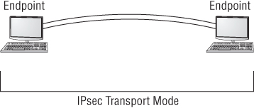
Figure 8.12 IPsec in tunnel mode
- The Encapsulating Security Protocol (ESP) can be used to totally encapsulated and encrypt the original packet. Security associations (SAs) maintain the information concerning the symmetric encryption algorithm that has been agreed upon between the parties. Symmetric keys can be exchanged, either out-of-band or through a Diffie-Hellman key exchange. This key exchange is referred to as the Internet Key Exchange (IKE). Due to its wide acceptance and versatility, IPsec was originally selected as the security protocol to be mandated in IPv6. Since this mandate was put into effect, it has been reduced to an optional security protocol in IPv6.
Remote User Authentication Services
There is a requirement to authenticate users who are not physically connected to the network within a building or workplace, such as users who may be working from home, are on assignment in other locations, or are on the road traveling. There may be also users who are assigned to remote offices and request enterprise network access.
There are several means to centrally administer the authentication of remote users as they request access to the enterprise network. RADIUS and TACACS provide centralized authentication services for remote users.
RADIUS
Remote Authentication Dial-In User Service (RADIUS) is a protocol and system that allows user authentication of remote and other network connections. The RADIUS protocol is an IETF standard, and it has been implemented by most of the major operating system manufacturers. Once intended for use on dial-up modem connections, it now has many modern features.
A RADIUS server can be managed centrally, and the servers that allow access to a network can verify with a RADIUS server whether an incoming caller is authorized. In a large network with many users, RADIUS allows a single server to perform all authentications.
Since a RADIUS server may be used to centrally authenticate incoming connection requests, it poses a single point of failure. Many organizations provide multiple servers to increase system reliability. Of course, like all authentication mechanisms, the servers should be highly protected from attack.
TACACS/TACACS+/XTACACS
Terminal Access Controller Access Control System (TACACS) is a client-server environment that operates in a similar manner to RADIUS. It is a central point for user authentication. Extended TACACS (XTACACS) replaced the original TACACS and combined authentication and authorization along with logging, which enables communication auditing. The most current method or level of TACACS is TACACS+, and this replaces the previous versions. TACACS+ has been widely implemented by Cisco and possibly may become a viable alternative to RADIUS.
Local User Authentication Services
Identification and authentication are required of all users of the network. Every network must have a method of determining who has access and what rights they have once they are allowed access. Access control may be provided through a number of different methods.
LDAP
Lightweight Directory Access Protocol (LDAP) is a standardized directory protocol that allows queries to be made of a directory database, especially in the form of an X.500 format directory. To retrieve information from the directory database, an LDAP directory is queried using an LDAP client. The Microsoft implementation of LDAP is Active Directory (AD). LDAP is the main access protocol used by Microsoft's Active Directory. LDAP operates, by default, at port 389, and the syntax is a comma-delimited format.
Kerberos
Kerberos is an authentication, single sign-on protocol developed at MIT and is named after a mythical three-headed dog that stood at the gates of Hades. It allows single sign-on in a distributed environment. An attractive feature of Kerberos is that it does not pass passwords over the network. The design is also unique in that most of the work is provided by the host workstations and not the Kerberos server. Figure 8.13 illustrates a simplified version of the Kerberos process.

Figure 8.13 Kerberos diagram
Kerberos authentication uses a key distribution center (KDC) to maintain the entire access process. As you can see in Figure 8.13, the KDC authentication server authenticates (steps 1 and 2) the principal (which can be a user, a program, or a system) and provides it with a ticket-granting ticket, or TGT (step 3).
After the ticket-granting ticket is issued, it can be presented to the ticket-granting server, or TGS (step 4) to obtain a session ticket to allow access to specific applications or network resources. The ticket-granting server sends the user the session ticket granting access to the requested resource (step 4). The user then presents the session ticket to the resource requesting access (step 6).
Through the use of a trust system, the resource authenticates the ticket as coming from the key distribution center and allows access for the user. Tickets are usually timed and will timeout after an eight-hour default unless set differently.
Kerberos is quickly becoming a common standard in network environments due to its adoption as a single sign-on methodology by Microsoft.
Single Sign-On
On larger systems, users must access multiple systems and resources on a daily basis. A major problem exists for users if they are required to remember numerous passwords and usernames. The purpose of single sign-on (SSO) is to allow users to use one set of logon credentials to access all the applications and systems they are authorized to access when they log on.
With the Kerberos system, a single session ticket allows any “Kerberized” resource to accept a user as valid. It is important to remember in this process that each application you want to access using SSO must be able to accept and process the Kerberos ticket. Some legacy applications require a script that accepts a password or user credentials and then processes the information by inserting it into the correct places in the legacy application to log the user on.
Active Directory (AD), on the other hand, retains the information about all access rights for all users and groups in the network. When a user logs on to the network, Active Directory issues the user a globally unique identifier (GUID). Access control is provided by the use of this GUID, and applications that support AD can use this GUID to allow access.
Using AD simplifies the support requirements for administrators. By using the assigned GUID, the user doesn't have to have separate sign-on credentials for Internet, email, and applications. Access can be assigned through groups such as role-based access control and can be enforced through group memberships.
SSO passwords are stored on each server in a decentralized network. Since a compromised single sign-on password would allow an attacker free reign on a network, it is important to enforce password changes and make sure certain passwords are updated throughout the organization on a frequent basis.
Although SSO offers a single point of failure in a potential security risk should a password be compromised, it is still better than having the user personally manage a large number of passwords for various applications and system resources. The tendency for an overwhelmed user is to write down usernames and passwords and place them in close proximity to the computer system. Single sign-on, despite all the possible headaches, can still be a substantial security benefit to an organization.
Federation
A federation is an association of nonrelated third-party organizations that share information based on a single sign-on and one-time authentication of a user. Figure 8.14 illustrates a travel booking site that would have a federated relationship with hotels, car rental agencies, and air carriers. Once the user signs on to the travel booking site, user inquiries and ultimately booking selections will be coordinated with the federated organizations without the individual having to log in to each organization's website.

Figure 8.14 Single sign-on with federated access
Network Segmentation
On a LAN, hosts can communicate with each other through broadcasts, and forwarding devices such as routers are not needed. The number of broadcasts grows as the LAN grows. It stands to reason that with more hosts, more data collisions can be expected, and ultimately the performance of the network will be slower.
Shrinking the size of the local area network through segmenting it into smaller groups reduces the number of hosts in each group. This reduces the size of broadcast domains by reducing the total number of collisions possible in a segment. Advantages may be realized by subdividing a local area network into smaller segments, which will improve overall network performance and manageability.
Subnetting
One of the issues to consider when designing a network is how to subdivide it into usable domains. There are numerous ways to divide a local area network. It may be accomplished logically, topologically, physically, by workgroups, by physical building, and in almost any other way you can think of.
Networks are subnetted by using segments of the IP address. For instance, an internal local area network address for a specific host machine might be 38.8.210.2. In this example, 210 is the number of the network, and 2 is the number of a specific host machine on network number 210. Figure 8.15 illustrates a three-segment network set up as three subnets. Note the differences in the IP addresses of the separate network segments.
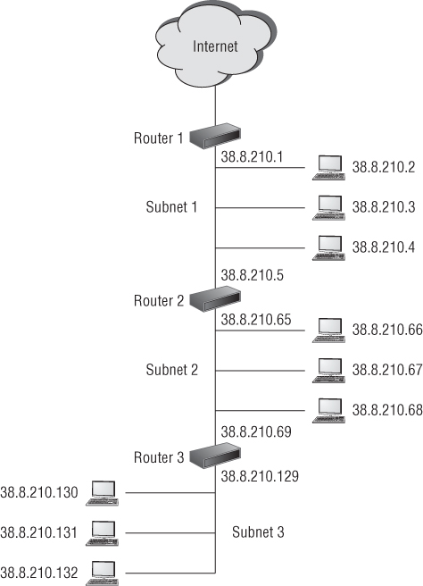
Figure 8.15 Example of a three-segment network
A special tool called a subnet mask value is used for subnetting. It covers up numbers in the address that are not required. When a network is subnetted, it is divided into smaller components, or subnets, with a smaller number of host machines available on each subnet.
The broadcast domain for a subnet is much smaller and has fewer hosts. The advantage to this is much better network performance because you are reducing overall network traffic while also making the network more secure and manageable.
Virtual Local Area Networks
A virtual local area network (VLAN) is created by grouping hosts together. Hosts may be grouped by workgroups, departments, buildings, and so on. The hosts in a VLAN are connected to a network switch. The switch is responsible for controlling the traffic that is destined for each host based upon each hosts Mac address. Members of the VLAN do not necessarily need to be in the same area. They can be in another office or even in another building. The VLAN can be used to control the path data takes to get from one point to another and may constrain network traffic to a certain area of the network. VLANs differ from subnets in that they do not provide security.
Demilitarized Zones
A demilitarized zone (DMZ) is a network segment created between two firewalls, one of which faces an untrusted network such as the Internet, so that some servers on an enterprise network can be accessed by external communications. The purpose of a demilitarized zone is to allow people you might not trust otherwise to access a public server, database, or application without allowing them on to the internal local area network.
When a server is positioned in a DMZ, it may be accessed by both untrusted users such as those on the Internet, as well as users from the trusted internal network. Figure 8.16 illustrates three servers placed in a demilitarized zone formed by two firewalls. Note that the internal network is completely shielded from both the Internet and the demilitarized zone by a firewall.

Figure 8.16 Illustration of a demilitarized zone
Devices placed in the DMZ are subject to attack. Routers, switches, servers, intrusion protection devices, and any other items that are exposed to the outside network must be hardened against attack. This means removing any unused services and protocols and closing all unused ports. After an attack, you might have to re-image or rebuild demilitarized zone network devices after an attack. Systems that allow public access and that are hardened against attack are usually referred to as bastion hosts. It is expected that bastion hosts may be sacrificed from time to time.
When establishing a DMZ, you assume that the person accessing the resources isn't necessarily someone you would trust with other information.
Network Address Translation
Network address translation (NAT) is primarily used to extend the number of usable Internet addresses. IPv4 has since run out of unique network addresses. Therefore, organizations create their own IP addresses for their internal network using a translation methodology to convert from the internal IP addresses to the external IP address.
Network address translation allows an organization to exhibit a single unique IP address to the Internet for all hosts and servers on the internal network. The network address translation server provides internal IP addresses to the hosts and servers in the network and translates inbound and outbound traffic from the external IP address to the IP addressing system used internally. The only information that an intruder will be able to see is that the organization has a single IP address. The connection between the Internet and the internal network is usually through a NAT server or a router.
Network address translation assigns internal hosts private IP addresses. These addresses are private and nonroutable across the Internet. The specific address ranges used for internal hosts IP addresses are as follows:
- 10.0.0.0–10.255.255.255
- 172.16.0.0–172.31.255.255
- 192.168.0.0–192.168.255.255
The NAT server operates as a firewall for the network by restricting access from outside hosts to internal network IP addresses. Through NAT, the internal network is effectively hidden from untrusted external networks. This makes it much more difficult for an attacker to determine what addresses exist on the internal network.
Securing Devices
There are various methods used to secure devices. Devices can be prepared or hardened against attack and also set up in such a way as to communicate with each other securely.
MAC Filtering and Limiting
MAC filtering is a method whereby known MAC addresses are allowed and those that are not wanted are not allowed on the network. This is a type of white list/blacklist filtering. Even in small home networks, MAC filtering can be implemented because most routers typically give you the option of choosing to allow only computers with MAC addresses you list on an authorized access control list.
MAC filtering can also be used as a wireless identification access control. Most wireless devices offer the ability to turn on MAC filtering, but it is off by default. Although a user may wish to join with a network using the SSID of a wireless system, the wireless system may refuse a connection based upon the MAC address not being unauthorized. In various network access control implementations, the term network lock is used to describe MAC filtering, and the two are synonymous.
MAC limiting is specific to some brands of network switches and is used to enhance port security on the switch by setting the maximum number of MAC addresses that can be learned (added to the Ethernet switching table) on a specific access interface port or all of the interface ports.
Unfortunately, MAC addresses may be spoofed relatively easily. Therefore, MAC filtering and limiting are not always foolproof.
Disabling Unused Ports
Part of system hardening is to disable all unused ports. Otherwise, they present an attack vector for an attacker to exploit. Any type of firewall implementation can be used to close or disable communication ports.
Security Posture
Many organizations are required to be in compliance with mandates such as HIPAA, PCI, and other relevant regulatory or contractual (industry) standards. Therefore, the security state of a network must be considered at all times.
It is important to establish a security baseline to document the network configuration. The baseline must represent a state in which you know the network is secure. Any future network or device audits will be compared to this state. A network or device baseline will also be referred to when conducting regression analysis after any changes have been made to the network or device to see if anything has changed from the original baseline. It is impossible to evaluate device or network security without having a baseline configuration documented.
The security baseline documents the current security configurations of network devices, which includes current patches, updates, sensitivity settings, and other configuration information. Network data flow and statistical information should also be included in the security baseline for later comparison and analysis.
Firewall and Proxy Implementation
From the early days of network design, firewalls have been the backbone of network security. They are used to separate a trusted network from an untrusted network and allow through traffic based on filtering rules. Firewalls are one of the primary methods for hardening host machines.
Firewalls
A firewall is an essential line of defense within a network system. They separate networks from each other and specifically separate interior networks from untrusted networks such as the Internet. A firewall is used as a border gate, usually depicted in drawings as a brick wall on the perimeter of the network.
There are many different types of firewalls, which can be either implemented as stand-alone appliances or embedded as an application within other devices, such as servers or routers. Operating systems such as Windows includes a host-based firewall.
Packet Filter Firewalls
A packet filter firewall passes data based upon packet addressing information. It does not analyze the data included in a packet but simply forwards the packet based upon an application or port designation. For example, a packet filter firewall may block web traffic on port 80 and also block Telnet traffic on port 23. This is the standard filtering mechanism built into all firewalls. If a received packet specifies a port that isn't authorized, the filter will reject the request or simply ignore it. Most packet filter firewalls may also filter packets based on IP source address and allow or deny them based on the security settings of the firewall.
Proxy Firewalls
A proxy firewall uses increased intelligence and packet inspection methodology to better protect the internal network. A proxy is always described as an intermediary between two systems, hosts, or networks. In effect, a proxy firewall isolates the internal network from the external untrusted network by intercepting communications. It does this by receiving a packet from an external untrusted source and repackages it for use by the internal protected network host. During this process, the untrusted source does not have direct access or even IP address knowledge of the internal host. Once the internal host decides to reply to the message, it sends the response message to the proxy firewall, which then repackages it, stripping off the internal IP address and sending it on to the external untrusted host.
A proxy firewall can provide additional services through its ability to cache information. Information such as frequently used web pages or documents is stored in memory and resent to the internal host should the request be made again.
Firewalls sometimes contain two network interface cards (NICs), one connected to the external network and one connected to the internal network. When two network interface cards are used on a firewall, the firewall is referred to as a dual-homed firewall. The controlling software within a firewall effectively separates both network interface cards, thereby reducing the possibility that an attacker will bypass the firewall security.
Stateful Packet Inspection Firewall
Stateful packet inspection (SPI) firewalls analyze packets to determine the external originating source as well as the destination on the internal network. This type of firewall records this information as a continuity of conversation record. It keeps the record using a state table that tracks every communication channel.
A stateful firewall compares existing conversations with new packets entering the firewall connecting for the first time. The new packets are compared against rulesets for a decision about whether to allow or deny. Other firewalls that do not track the continuity of conversations and only make allow or deny decisions based upon simple rulesets are referred to as stateless firewalls.
Web Application Firewall
A web application firewall (WAF) is a specialized firewall used to regulate traffic to and from web servers and specialized web applications. It utilizes specialized rules such as content filtering, access control, and intelligent rulesets that are customized specifically for the web application.
A web application firewall operates at the highest layer of the OSI model, layer 7, and is dedicated to filtering traffic into and out of a web application or web server operating in real time. It operates as a very sophisticated intrusion protection system and protects against content-based attacks such as cross site scripting (XSS), injection attacks, and HTTP forgery attacks.
Firewall Rules
Firewalls enforce various types of rulesets. The rules can be very specific, allowing or denying a specific IP or port address, or very general, allowing total access to a specific port such as HTTP port 80. Firewall and router rules may exist by default, meaning they are built into the system. These types of rules are referred to as implicit rules. Explicit rules are those specifically created to perform a certain function, like blocking a port or IP address.
Firewall rules is a list of statements used to determine how to filter traffic and what can pass between the internal and external networks. A firewall might have dozens if not hundreds of rules. There are three possible actions that can be specified in a firewall rule:
- Deny the connection.
- Allow the connection.
- Allow the connection if it is secure.
Firewall rules can be applied to both inbound traffic and outbound traffic. Firewalls may be placed anywhere within a local area network. For instance, firewalls can separate workgroups, filter inbound traffic from the wireless network, filter traffic to and from a virtual private network, and be dedicated to a specific server or application to filter content traffic.
Firewall rules may be constructed using various techniques. Some of these techniques are described in the following sections.
Access Control Lists
An access control list (ACL) is a list that specifies the actions that a user or system is granted to perform. An access control list allows a subject, which may be a user, system, or application, to access an object, which may also be a user, system, or application. The access control list usually specifies the rights and privileges allowed. For instance, at the root level, an access control list may specify allowing access to the object. At a higher level, the access control list may then specify what permissions the subject has, such as read, write, read/write, delete, create, or other permissions.
Access control lists can be used by both firewalls and routers to build rulesets that allow or deny access to various network resources.
Implicit Deny
Implicit deny is a type of access rule that states that if a subject is not listed on the access control list, access is denied. This type of rule is usually at the bottom of the rules list in either a router or a firewall. Its purpose is to act as a catchall. If entry has not been explicitly granted, it is implicitly denied. In other words, the implicit deny rule catches anything to which no other rule applies and denies access.
In an access control list, this is a type of white listing. In a white list, only entities such as a source address, a destination address, and a packet type may be allowed access. Anything not on the white list is denied. In a blacklist, everything you wish to deny must be listed. This would prove to be a huge list.
Network Routers and Switches
Routers and switches are the primary network devices used for connectivity and local area networks. Relying on different addressing schemes, these devices forward data on the network based on logical addresses or physical addresses. They may also be used to divide a network into segments.
Routers
A router is a networking device used for connectivity between two or more networks. They operate by enabling a path between the networks based on packet addresses. Routers perform a traffic-directing operation within a LAN and over a network such as the Internet. Reading the destination address on a packet, the router, based on a routing table or internal rule, will forward the packet to the next network and router. This forwarding will continue until one of two events occur. Either the packet reaches its end destination or the counter on the packet, referred to as a “hop” counter, reaches zero, meaning it has exceeded the number of routers it has crossed and therefore the packet will be discarded.
Routers exchange information about destination addresses using a table listing the preferred routes between any two systems on an interconnected network. This routing table is created using a dynamic routing protocol.
The routing table contains information concerning destinations and local connections to which the router has immediate access. A routing table contains information about previous paths and where to send requests if the packet destination is not in the table. Tables expand as connections are made through the router.
Routers communicate with each other and share information using one of several standard protocols. These protocols include Routing Information Protocol (RIP), Open Shortest Path First (OSPF), and Border Gateway Protocol (BGP).
Routers can be configured in a number of ways, including as a packet filtering firewall and as an endpoint device for a virtual private network. Routers may also have different types of interfaces that accommodate various types of transmission media. This media includes fiber-optic cables, twisted-pair copper wire, and wireless transmission using modulated radio waves.
Local area networks can be subdivided into segments by routers based on IP addresses, effectively creating zones that operate autonomously. Each segment will have a unique subnet address. Subnets may be a logical group, a workgroup, a building, or any other subjective grouping of hosts or servers. Within a network, routers can be connected to other routers.
Data Plane and Control Plane
A router has two operational stages called planes. Each plane is part of the architecture of the router and has an individual responsibility when receiving and forwarding packets.
- Control Plane The control plane is the part of the router that is concerned with determining the path that should be used to forward a data packet. It maintains a routing database and also determines the proper router interface port to use. Packet routes are established either through the use of preprogramming static routes, which can be edited manually, or through the router control plane learning dynamic routes from other routers around it through using one of several dynamic routing protocols.
- Forwarding Plane The forwarding plane, sometimes referred to as the data plane, is the part of the router that receives arriving packets and routes them through an output interface to the destination address. The forwarding plane utilizes destination addresses obtained by the control plane and maintained in routing tables.
Secure Router Configuration
A primary responsibility with many SSCPs is to work with and maintain router configurations. It is also important to make sure router configurations are secure. There are several simple steps that can be taken with every network device to ensure network security.
- Keep the firmware upgraded. Manufacturers quite often issue patches and upgrades in response to attacks or to resolve various problems that might occur with a piece of equipment. It is important to maintain an up-to-date patch level on each piece of equipment. Prior to installation, patches should always be tested in offline, nonproduction equipment. Installation of patches should be thoroughly documented and be in compliance with the change control methodology of your organization.
- Change the default password. A default password is loaded at the factory when every piece of equipment is built. Unfortunately, many organizations will put pieces of equipment into production without changing the default password. Passwords on networking equipment should be changed for initial installation and then updated in accordance with the password policy of the organization.
- Use advanced configuration settings. Most pieces of networking equipment offer advanced configuration options for ICMP requests, MAC filtering, and various other specialized settings. Depending upon the router, options may differ, but by setting them correctly, network security can be enhanced.
- Establish a baseline. A baseline is an established performance level or benchmark, for each piece of equipment. Once changes are made, such as adding patches or upgrades, the performance can be measured against the previous baseline.
- Create configuration backups. Equipment settings should always be backed up prior to making any changes or upgrades. This allows for a fallback position should a patch or upgrade fail.
Switches
A switch is a network device that routes traffic based on physical MAC addresses. Most switches contain very little programming or intelligence. Previously, hosts on a network were connected by network hubs that forwarded the same information to each host. Modern switches are multi-port networking appliances that forward data to one or multiple devices.
Operating at the Data Link layer (layer 2) of the OSI model, switches switch information based on MAC addresses and are used to assemble virtual local area networks using a star network topology model. Virtual local area networks (VLANs) that are created through the use of a switch are not natively secure because the data within one virtual private network could possibly be exposed to other network segments. This is referred to as the VLAN “hopping.”
More intelligent network switches combine the ability to switch MAC addresses as well as route IP addresses. Because IP addresses are at OSI layer 3, this type of switch is referred to as a layer 3 switch.
Intrusion Detection and Prevention Devices
Intrusion detection and prevention is a method of monitoring data traffic through the network to determine, based upon some criteria, if the information flow is correct. Upon detection, certain actions may be taken to record the event, alert operators, or take actions that may involve blocking the intrusion.
Intrusion detection (ID) can be described as the passive process of monitoring various characteristics in a system or network to determine if an event is occurring. An intrusion is any activity, process, or action that attempts to circumvent or compromise the confidentiality, integrity, or availability of an organization's resources.
Intrusion Detection Systems
An intrusion detection system (IDS) is software that runs either on a host workstation or on a network appliance. Depending upon the location, the system may be referred to as a host intrusion detection system (HIDS) or network intrusion detection system (NIDS). The primary role of a detection system is to monitor and analyze network traffic. This is a passive role, and no action is taken on the traffic itself.
There are two primary measurements of network activity used in setting up and fine-tuning an intrusion detection system:
- Baseline A baseline is a predetermined level of expected activity on a network segment or network component. It may vary by day or by the hour. An intrusion detection system may be tuned to expect a certain volume of traffic or a specific type of packet being sent over the network.
- Clipping Level A clipping level is an activity level established above the baseline that, when crossed, sets off an alarm or initiates some activity based upon an increased level of traffic on the network segment (Figure 8.17). A clipping level reduces noise and log entries.

Figure 8.17 Illustration of a baseline and a clipping level
An intrusion detection system is a passive system that listens and alerts. The system is connected to the network through the use of a network tap or three-way connector that allows the device to monitor network traffic. An IDS is not inline in the network and does not provide a single point of failure.
Intrusion Prevention Systems
An intrusion prevention system (IPS) is software that runs either on a host system or on a network appliance. The IPS not only detects a potential attack, it takes a predetermined action to stop the attack. For example, if it appears as if an attack might be in progress, identified packets might be dropped, ignored, logged, or otherwise dealt with. Operators might be alerted, and other actions, such as changing of firewall rules to block a port or IP address, might be initiated. While an intrusion detection system is a passive device, an intrusion prevention system is an active device.
For an intrusion prevention system to work it must be in line with the network data stream. This is so it may take immediate action to drop or block packets or take any other action based upon its ruleset. It also creates the problem that the IPS may become a target for an attack and that by being in the data stream, it is a single point of failure.
Both IDSs and IPSs utilized four primary methods of network monitoring:
- Behavior-Based Detection A behavior-based monitoring system monitors network traffic behavior, such as unusually high traffic, high-volume traffic destined for a specific port, high-volume traffic destined for specific IP address, and unusual control or request packets. Behavior-based detection is monitoring deviations in behavior from established baseline standards.
- Signature-Based Detection A signature-based monitoring system monitors network traffic based on previously established signatures of typical attacks. Similar to an anti-malware identification system, this type of system might identify different types of attacks through the methods used during the attack. For instance, a SYN flood attack is characterized by an attacker sending a large number of SYN packets with no responding acknowledgment packets. This opens a very large number of communication sessions. Other types of attacks can be identified through a library of signatures, thus triggering a response or action against the attack. Signature libraries must be kept up-to-date for this type of detection to be effective.
- Anomaly-Based Detection An anomaly-based monitoring technique is very similar to a behavior-based monitoring system in that it looks for something completely outside of the ordinary. This type of device is usually more intelligent and learns what normal looks like from the typical traffic flow and activity on the network. Should anything out of the ordinary appear, the device would then take action. An anomaly-based device can be set within established baselines or be set to use automated processes to monitor traffic patterns to determine the baseline.
- Heuristic-Based Detection A heuristic-based monitoring technique produces a solution by monitoring network traffic and providing a result based on good enough information. A type of learning system, it uses just enough information to arrive at a solution. Thus, it is very fast, but it is also potentially inaccurate. A heuristic system uses algorithms to analyze traffic passing through a network; the algorithms can be used by themselves or in conjunction with other techniques and information to improve their efficiency and accuracy.
Many manufacturers are concentrating their efforts on the development of heuristics and intelligent sensing devices rather than signatures and baseline monitoring. The downside is that the systems are prone to errors if not adjusted correctly.
Wireless Intrusion Prevention Systems
A wireless intrusion prevention system (WIPS) is used to mitigate the possibility of rogue access points. These systems are typically implemented in an existing wireless LAN infrastructure and enforce wireless policies within an organization. They prevent unauthorized network access to local area networks through unauthorized access points.
A wireless intrusion prevention system might be simply a workstation with an antenna running a specialized sniffing application. A typical wireless intrusion detection system receives wireless transmitted packets, analyzes the packets, and then correlates against existing IT policy standards. Upon identification of a violation and classification of a threat, the WIDS administrator is alerted.
Several components work together to form a wireless intrusion prevention system:
- WIPS Sensors A wireless intrusion prevention system uses antennas and radio receivers that scan the 2.4 GHz and 5 GHz wireless spectrum and accumulate all packets transmitted. Such sensors may be installed throughout the internal perimeter of the organization. Packets are stored and forwarded to a centralized server for analysis.
- WIPS Processing Server A wireless intrusion prevention system uses a centralized server for analysis. The centralized server utilizes specialized wireless packet detection software that inspects packets against specific packet signatures as established by the policies of the organization. The WIPS processing server correlates the information, validates it against the defined rules, and notifies an administrator if it meets threat criteria.
- WIPS Multi Network Controller In very large organizations, a multiple-network controller is used, which is made up of several sensors and servers dispersed in geographic locations that coordinate a number of WIPS processing servers.
Comparing Intrusion Detection Systems and Intrusion Prevention Systems
While intrusion detection systems began the intrusion detection revolution, intrusion prevention systems have far surpassed them in popularity and integration into modern networks. NIST now classifies both IDS and IPS as one type of device, an intrusion detection and prevention system (IDPS).
Intrusion Detection Systems
Although older than intrusion prevention systems, intrusion detection systems served their purpose and are still in use in many networks today.
Advantages
- Offer offline monitoring. May easily be connected to a network tap.
- Not inline with network information.
- May easily be tuned to monitor for specific information.
- May trigger recording of logs.
- May alert operators.
Disadvantages
- Early versions may be hard to tune and adjust.
- No actions taken on other learning operators.
- Incredible amount of data captured if not filtered properly.
Intrusion Prevention Systems
Intrusion prevention systems with advanced anomaly and heuristic sensing are the wave of the future. They take immediate action such as terminating a communication session based on triggering of various rulesets. In today's market, this product may be known as an IDS/IPS or just as an IPS. Since an intrusion detection system only alerts operators or initiates log files, the most popular device to purchase would be an intrusion prevention system that can take a predetermined action. This would potentially protect the network while it is logging and alerting.
Advantages
- Offer in-line monitoring. May easily be connected directly into the network data stream.
- Are directly inline, thus can take immediate action.
- May easily be tuned to monitor for specific information.
- Identify malicious activity, log information about this activity, attempt to block/stop it, and report it.
- Perform actions as sending an alarm, dropping the malicious packets, resetting the connection, and/or blocking the traffic from the offending IP address.
Disadvantages
- Hard to tune and adjust.
- May be complex for users to learn and understand.
- May provide a self-inflicted denial of service if not tuned correctly due to the fact they may drop packets indiscriminately.
Spam Filter to Prevent Email Spam
To prevent email spam, such as unsolicited email, various email systems use antispam techniques. Unfortunately, the techniques are not without the downside of sometimes eliminating legitimate emails or sending them to spam folders. Antispam techniques can be broken into four broad categories:
- Actions that must be taken by individuals
- Actions that may be taken by email administrators
- Actions that may be taken by those who send email
- Actions that may be utilized by data researchers and law enforcement officials
No technique is a complete solution that offers a trade-off between incorrectly rejecting legitimate email and rejecting all spam.
There are a number of appliances, services, and software systems that system administrators may use to combat spam within their network systems. Lists of known spam sites are available to administrators so they can blacklist known spammers from their networks. Another spam elimination and blocking technique uses specialized analysis of the message patterns to detect spam or typical spam behavior and then compare it to global databases of spam.
Telecommunications Remote Access
Network boundaries are becoming more obscure every day. Network administrators used to have full control over every device connected to the network. But with the advent of portable personal devices, there are more and more requests for network connectivity. Every individual has two or three personal devices they wish to bring to work and use on the job. Driving the revolution are the senior executives of the organization who need 24/7 connectivity with their personal devices. It is hard to say no when the tidal wave of public opinion is against you.
System administrators must grapple with the fact that Bring Your Own Device (BYOD) is very much a reality to be dealt with virtually immediately.
Network Access Control
Network access control (NAC) is a technology approach to control the wellness and hygiene of a device desiring connection to a network. NAC is a network access solution that uses a set of predefined protocols to define and implement a policy whereby devices must meet various standards prior to being allowed access to a network.
When a device attempts to connect to a network, it must first be checked by a network application accessing a preinstalled software agent on the device to retrieve various device parameters and to ensure that the device complies with a network access policy. The network access policy may include requirements for antivirus protection level, system update level, and app configuration. During this period, the device can only access resources that can remediate any issues. Upon being certified as compliant, the device is able to access network resources and the Internet within the policies defined by the NAC system. NAC might integrate automated remediation processes to bring the device into compliance. Network access control is described in the 802.1X standard.
Network access control includes policies such as preadmission endpoint security checks and posted admission controls concerning the authorization of where users and devices can go on a network once access is granted.
Wireless & Cellular Technologies
Wi-Fi and cellular technologies have become the mainstay of communication, not only at home but throughout the business community. Today it's hard to remember when any of us did not have a telephone in our pocket or purse. Portable devices such as cell phones and personal digital assistants (PDAs) as well as laptop computers and tablets have become commonplace in our lives. It is only natural that everyone wants to bring them to work and use them at their desk or job location.
There still is controversy among security professionals as to how to come to terms with increased worker productivity on the one hand and organizational asset security on the other. While it might be expected that some highly restricted government facilities and defense contractors have policies completely banning wireless cellular and other portable technologies in the workplace, it is becoming nearly impossible to enforce such restrictive policies in the business community.
It is important for the SSCP to understand the differences between wireless and cellular technologies as well as organizational policy and policy enforcement in the workplace.
IEEE 802.11x Wireless Protocols
IEEE 802.11 is a list of specifications for implementing wireless computer communications. Originally issued as a standard in 1997, the standard has received a number of amendments that are designated by a letter following the basic specification of 802.11 (Table 8.3). Various frequency bands have been allocated by the Federal Communications Commission (FCC) for implementing wireless local area networks. These frequencies include the 2.4, 3.6, 5, and 60 GHz frequency bands. Wi-Fi is a trademark of the Wi-Fi Alliance. It describes a local area wireless computer networking technology that allows electronic devices to communicate most commonly in the 2.4 GHz and 5 GHz bands.
Table 8.3 802.11 Standards and amendments
| Standard and Amendment | Description |
| 802.11 | The original IEEE 802.11 standard defines wireless local area networks that transmit at 1 Mbit/s or 2 Mbit/s using the 2.4 GHz frequency spectrum. |
| 802.11a | Amendment a provides wireless bandwidth up to 54 Mbit/s using the 5 GHz frequency spectrum. |
| 802.11b | Amendment b provides wireless bandwidth of up to 11 Mbit/s using the 2.4 GHz frequency spectrum. The specification also includes the ability to scale back to transmission rates of 5.5, and 2 Mbit/s for slower devices. Originally referred to as 802.11 high-rate, this was the original standard selected by the Wi-Fi alliance to be denoted as Wi-Fi. |
| 802.11g | Amendment g provides wireless bandwidth of up to 54 Mbit/s using the 2.4 GHz frequency spectrum. |
| 802.11i | Amendment i provides for security enhancements to the wireless standard and is referred to as WPA2 that uses the AES encryption algorithm. |
| 802.11n | Amendment n provides for wireless bandwidth in a range from 54 Mbit/s to 600 Mbps and can operate at both 5 GHz and 2.4 GHz. This amendment offers the greatest flexibility with the least amount of interference. |
WEP/WPA/WPA2
Over a period of time there have been a series of wireless security implementations. Several wireless security protocols have been used, each replacing another after weaknesses were exposed. The following sections discuss the relative capabilities of the wireless security protocols.
Wired Equivalent Privacy (WEP) was intended to provide basic security for wireless networks, while wireless systems frequently use the Wireless Application Protocol (WAP) for network communications. Over time, WEP has been replaced in most implementations by Wi-Fi Protected Access (WPA) and WPA2. The following sections briefly discuss these terms and provide you with an understanding of their relative capabilities.
Wired Equivalent Privacy
In the early days of wireless communication, there was a need for a wireless protocol designed to provide data privacy through an encryption methodology that was equivalent to the encryption methodology used for wired networks. Wired Equivalent Privacy (WEP) was said to be just as good and “equivalent” to the type of encryption protection available on wired networks of the time and was therefore implemented on a wide number of wireless devices.
WEP was found to be vulnerable to attack due to the implementation of the RC4 encryption algorithm. At the time, an initialization vector of only 24 bits was used in the implementation. This allowed for predictable key patterns, and thus RC4 proved to be easily cracked in as few as 30 seconds with a standard PC.
Wi-Fi Protected Access and WPA2
With the serious weakness and eventual cracking of WEP, the wireless industry required a more secure replacement to secure wireless communications. The Wi-Fi Alliance initially developed Wi-Fi Protected Access (WPA) in 2003 as a replacement for WEP. This was originally intended only as an intermediate step while a more complex and secure standard was developed.
A primary criteria for a WPA replacement was that it had to be backward compatible to existing WEP hardware currently in the field. Temporal Key Integrity Protocol (TKIP), which utilizes a dynamically changing 128-bit key for every packet, was implemented along with the original RC4 encryption algorithm.
As of 2004, the Wi-Fi Alliance replaced WPA with Wi-Fi Protected Access II (WPA2). WPA2 is a much stronger encryption product and uses Advanced Encryption Standard (AES) as the encryption algorithm. This encryption method is referred to as Cipher Block Chaining Message Authentication Code Protocol (CCMP), which utilizes AES operating in counter mode with a 48-bit initialization vector. A significant cryptoanalysis Work Factor (WF) is required to brute-force crack the algorithm password. This encryption method also minimizes the risk of a replay attack. WPA2 certification by the Wi-Fi Alliance is mandatory for all new devices that bear the Wi-Fi trademark.
WPA2 is the foundation encryption method adopted by the IEEE as specified in the 802.11i standard.
Wireless Networks
A wireless network includes network nodes connected by a radio. Two types of network topology are used for wireless networks.
- Wireless Network A network consisting totally of wireless devices.
- Hybrid Wireless Network This is the more common implementation of the wireless network and consists of wireless devices connecting to an access point that then interfaces with a standard wired network.
Wireless networks are designed to achieve a specific purpose. Two types of connection and authentication modes are used in wireless network:
- Ad Hoc Mode The IEEE 802.11 standard provides for communication between two or more endpoints where no centralized access point is involved. As illustrated in Figure 8.18, ad hoc refers to the ability to initiate or terminate wireless communications at will between individual devices. The access control model used is discretionary access control. Authentication is usually not a consideration.

Figure 8.18 Illustration of an ad hoc mode wireless network
- Infrastructure Mode The IEEE 802.11 standard also provides for the communication of numerous wireless devices connecting through network access points (APs). Figure 8.19 illustrates devices connecting to a central access point. Access points are network nodes connected to a wired network. Formal access controls, including user authentication, are generally in place in infrastructure mode.

Figure 8.19 Illustration of the infrastructure mode wireless network zone
Several types of wireless networks exist to fill a specific purpose, topology, or user requirement. Figure 8.20 illustrates a small home network using a single wireless access point internal to a wireless router.

Figure 8.20 Illustration of a home network using a wireless router
Cellular Network
A cellular network contains a system of radio towers referred to as a cellular base stations and featuring directional radio transceivers and antennas to form of geographic cell. Each cell borders other cells to maintain continuous coverage over a large geographic area. A cellular base station and its radio antennas transmit on different frequencies from the adjacent cell. As cellular devices such as cellular telephones traverse the geographic area, a handoff is made between cellular base stations, which is completely transparent to the user (Figure 8.21).
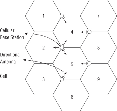
Figure 8.21 A cellular network illustrating geographical cells served by cellular base stations
WiMAX
The name WiMAX is a trademark and was created by the WiMAX Forum. It is specified in the IEEE 802.16 standard.
The original concept of WiMAX was to replace Wi-Fi as a connection medium of choice. WiMAX is intended as a much stronger and robust geographically based system covering a much larger physical area than Wi-Fi covers. There are significant differences between WiMAX and Wi-Fi, and with Wi-Fi already embedded with many major manufacturers, it may be difficult for the WiMAX Forum to compete.
While the initial concept involved WiMAX competing in the commercial user marketplace, it has found a significant niche in corporate and government implementations. For instance, several cities have initiated WiMAX digital communication systems for their emergency services, such as police, fire, and ambulance communications. Also, large industrial complexes such as chemical plants, oil refineries, and major manufacturing plants have incorporated WiMAX communications over a large-scale physical area. A WiMAX connection is highly reliable and favorably replaces traditional T1 or T3 connections by completely bypassing the local telephone line service providers.
Wireless MAN
A metropolitan area network (MAN) is a very large geographic network that connects groups of smaller networks or connects directly to end users. Originally intended for a metropolitan areas such as cities, business parks, and college campuses, a MAN is connected physically by dedicated wireless links using microwave, radio, or infrared laser transmission. Many MAN providers rent or lease wired circuits from common carriers because laying long stretches of cable is expensive.
A wireless MAN (WMAN) utilizes radio transmitters and receivers to communicate to wired LANs through access points or directly to wireless endpoints. The WMAN eliminates the requirement for the leased lines of a MAN.
Wireless WAN
A wireless wide area network (WWAN) utilizes standard cellular radio transmitters, receivers, and transceivers (cellular telephones, laptops, and cellular-enabled devices) to communicate to wired LANs through access points or directly to wireless endpoints. The WWAN essentially describes the existing cellular telephone network, where any user can connect to a local area network using any current cellular service. Users and existing local area access points are already set up to use a WWAN.
Wireless LAN
A Wireless LAN (WLAN) utilizes standard short-distance cellular radio transmitters, receivers, and transceivers (cellular telephones, laptops, and cellular-enabled devices) to communicate to wired LANs through access points. A WLAN may be characterized as a local area network where several user workstations connect using Wi-Fi to an access point installed in the room.
Wireless Mesh Network
In a mesh technology network, each node communicates with all of the other nodes. Mesh networks are redundant and usually very fast. They are referred to as “self-healing” because if one communication path fails, another communication path is immediately available. In a wireless mesh network, each node is immediately available and can forward messages to other nodes. A wireless mesh network can be implemented in an ad hoc communication relationship.
Bluetooth
Bluetooth has become famous for connecting items such as keyboards, mice, headphones, speakers, and other devices to a user workstation. Bluetooth has also been a conduit for communication between two Bluetooth-enabled devices such as computers, tablets, and cell phones. Originally designed as a low-power transmission medium to replace wires and cables, it has been expanded to a number of other uses, including data synchronization between devices. Using a low-power, Class II transmitter, Bluetooth has a general range of approximately 10 meters, or 33 feet, and has a stated maximum range of 100 meters, or 333 feet. It has been proven through experimentation that with the use of sophisticated specialized “shotgun” antennas, it is possible to extend the range to 2 miles.
Bluetooth originally started as an IEEE 802.15 standard and has since been relinquished by IEEE and is currently managed by the Bluetooth Special Interest Group.
Wireless Network Attacks
Because data is transmitted readily through the radio environment, it is subject to being captured either mistakenly or intentionally. There are a number of well-known attacks against wireless transmissions.
- Parking Lot Attack The parking lot attack is best characterized by a vehicle located within close proximity to a transmission source, such as in the parking lot of an organization. The attacker usually has sophisticated radio monitoring equipment.
- Drive-By Attack In a drive-by attack, attackers have already identified the target and either jam the target with powerful conflicting signals on the 2.4 GHz and 5.0 GHz bands, thus disrupting communications, or attempt to intercept communications.
- Wardriving The act of searching for wireless communications by driving through an area using antennas, software, and a portable computer. Wardriving may be also accomplished using smartphones or personal digital assistants.
- Warchalking The marking of symbols to advertise the availability of Wi-Fi networks and to indicate whether they are open. Similar to hobo symbols, warchalking symbols consist of a number of different hieroglyphs or icons that were usually more in shock on buildings with available Wi-Fi networks.
- Bluesnarfing The unauthorized use of Bluetooth to access information from a wireless device.
- Bluejacking Uses Bluetooth to send unsolicited messages to Bluetooth-enabled devices such as mobile phones, tablets, and laptop computers.
- Bluebugging A form of a Bluetooth attack in which the attacker accesses and uses all phone features.
- Evil Twin Referred to as an evil twin, a rogue Wi-Fi access point that appears to be a legitimate access point that is part of an enterprise network on the premises but has actually has been set up to eavesdrop on wireless communications.
Wireless Access Points
A wireless access point (WAP), commonly called an access point, or AP, is a low-power directional transceiver (transmitter/receiver) that is connected to the local area network through a standard network connection. The wireless access point associates with wireless devices within its immediate vicinity and transmits packets from the wired network to the wireless device.
Wireless devices such as cell phones, personal digital assistants, and laptops will connect to the “loudest” (in transmission volume) or nearest access point to their location. This is an attack technique commonly used by nefarious individuals to establish an access point that appears to be authentic but in fact just monitors all of the wireless information sent from an unsuspecting user's wireless device.
A typical method employed when spoofing an access point is for the attacker to use a secondary or rogue access point. This rogue access point will be under the control of the attacker and may be placed in closer proximity to the user machines that he wants to attack. In practice, the rogue access point will appear as the legitimate access point on the actual network to unsuspecting laptops and tablets and other digital devices. This rogue access point would then process or view all traffic destined for the original network and would appear to all users to actually be the access point of the original network. This is a typical attack method used in many public places, including airports and restaurants.
Antenna Placement
Antenna placement can be a major factor in the successful implementation of a wireless network. Antennas radiate electromagnetic radio signals that are received by wireless devices. Generally, common sense dictates that the farther a radio signal must travel, the weaker it will become. Placing an antenna near a metal object will disrupt the radio signal, as will placing the antenna near the floor or near a major electromagnetic frequency (EMF) source such as a motor, florescent light ballast, or transformer. Various other building materials may easily absorb or block radio waves, such as concrete blocks, metal doors, rock and stone structures such as fireplaces, and sometimes even metallized glass.
The ideal antenna placement is within the center of the area served and high enough to get around most obstacles. Many access points include a transmission signal attenuator control (transmitter volume control or power level control) that may be used if the signal transmits outside of the space intended.
Antenna Types
The selection of a wireless antenna is important to the success of a wireless access point. On most access points, the supplied antenna can be replaced by an alternate antenna. A replacement antenna may be selected to be more or less directional, allowing for the proper configuration within the work space. Some access points have antennas that are completely internal and thus are not accessible.
Other access points have one or more external pole antennas. The more sophisticated access points will have a radio assigned to each antenna and will select the strongest signal strength depending upon the location of the transmitter in relation to the antenna within the work space. Proper antenna selection can allow the signal to circumvent obstacles and minimize the effects of interference, thus increasing signal strength and focusing the transmission within the work space. This will ultimately increase the speed of data transmission.
There are several types of antenna to select from:
- Omnidirectional Antenna Designed to provide a 360° pattern and provide an even signal in all directions. An omnidirectional antenna may be typically found on home as well as commercial wireless access points. When this type of antenna is used, the desired AP location is in the center of the work area.
- Directional Antenna Designed to force or direct a radio signal in one direction. This allows the radio signal to cover a greater distance or to avoid obstacles. A directional antenna might be used to project a Wi-Fi signal down a hallway.
- Yagi Antenna A directional antenna consisting of multiple parallel metal rods called dipole elements in a line. As opposed to a simple dipole antenna, this design achieves a high degree of directionality and gain.
An antenna's power gain, or simply gain, is a major design feature that combines the antenna's beam focus and transmission efficiency. For instance, an antenna advertised with a 10 dBi would be 10 times stronger than a basic antenna of 0 dBi. Theoretically, every increase of 3 dBi effectively doubles the power output.
Traffic Shaping Techniques and Devices
Many companies struggle with limited bandwidth as applications, data transmission, and VoIP traffic seemingly clog up their networks. More and more data is transferred, and corporate network users transfer files, make phone calls, and analyze data to make corporate decisions. Network engineers and architects must ensure that business-oriented traffic gets priority over best-effort traffic. Traffic shaping has become the term used to manage the priority of traffic on corporate LANs.
Traffic shaping, which is also known as shaping, is a network traffic management technique that prioritizes packets in accordance with a network traffic profile. It is used to optimize or guarantee the delivery of some packets prior to others. This is accomplished by delaying some packets while accelerating others, thus improving network latency and increasingly the usable bandwidth.
Traffic shaping is also a method of controlling the volume of network traffic through the use of bandwidth throttling. The maximum rate at which the traffic is sent is controlled by rate limiting. Traffic shaping can be accomplished using a number of different methods, but in each case it is always achieved by prioritizing and delaying packets.
Quality of Service
Quality of service (QoS) is a measure of satisfaction of the overall user experience of the computer network or transmission medium. Some applications, such as multimedia, VoIP, and other streaming media, require a fixed-rate data flow and are sensitive to delays. If the network has excessive congestion or limited resources, excessive packet dropping and bit error rate may increase. If this happens, the quality of experience (QoE), which is a subjective business concept, will be markedly lower and very noticeable to users and may be measured by “user-perceived performance,” the required “degree of satisfaction of the user,” or the targeted “number of happy customers” with regard to a service-level agreement (SLA).
As business networks become more congested with both data and multimedia traffic, quality of service and maintaining user satisfaction are growing in importance.
Summary
As a security practitioner, you will be closely involved with various aspects of managing and controlling networks, providing security, working with wireless applications, installing and administering updates and patches, and many other hands-on activities. As such, it is important to understand the basic concepts of each practice.
In this chapter, you studied the OSI reference model as well as the TCP/IP reference model. Both models are used to illustrate the encapsulation of data when it's transported over media to a different address. The OSI model features seven layers, while the TCP/IP model has only four layers. Copper wires, radio transmission, and fiber-optic cable are all forms of media. IPv4 and IPv6 describe the IP protocols that are used to route packets between devices. It is important to remember that the IPv4 address space is 32 bits while the IPv6 address space is 128 bits. There are numerous ways for a device to access the media. Carrier sense is the process when a device is listening for signals on the media, while multiple access is the ability for all devices to speak at the same time. This was referred to as carrier sense multiple access. In the event of two devices transmitting at the same time, there are two different techniques, collision detection and collision avoidance, that are used to resolve the contention.
In this chapter we covered various types of data traveling over networks, including streaming media, such as VoIP and multimedia files that include audio and video files. Continuous network monitoring and management of network logs is very important to mitigate problems that may arise on the network as well as to be in compliance with various regulations.
Handling data in transit as well as authenticating users sending data or requesting access to the network is important. Knowledge of IPsec is useful because it will become a standard with the implementation of IPv6. Single sign-on techniques allow users to use one set of credentials to access network resources. Kerberos is a popular single sign-on authentication application. Network segmentation reduces the amount of congestion on a network by dividing the network into virtual local area networks, or subnets. Special networks called demilitarized zones are exposed to the trusted network and maintain servers and devices that require public access from the untrusted network or Internet.
Numerous network devices provide security services throughout the network. Firewalls filter data packets based on established criteria, such as sending or receiving IP addresses, port addresses, applications, and other information. Switches operate at layer 2 of the OSI model and switch information based on physical MAC addresses. Routers operate at layer 3 of the OSI model and route information based on logical IP addresses. A proxy refers to any device that is in between two networks and intercepts, translates, and forwards data. Intrusion prevention and detection systems monitor and analyze network traffic and either record or take action based on preset rules.
Wireless technology has become a central communication standard within modern networks. The IEEE 802.11 standard, along with its amendments, is central to understanding the available frequencies and data flow rates as well as security on wireless networks.
Many different types of traffic are now transmitted over networks. Some of this traffic, such as VoIP and streaming media, is very sensitive to congestion, and the dropping and delaying of packets may be quite noticeable to users. Quality of service involves techniques to prioritize packets on a network, thus improving user satisfaction.
Exam Essentials
- Network Models Be able to describe both the TCP/IP model and the OSI model.
- Network Cabling Understand different types of network cables, including twisted-pair and unshielded twisted-pair, fiber-optic cables, and coaxial cables.
- Fiber-optic Cables Know the difference between single-mode, multimode, and plastic optical fiber, including the benefits and uses of each.
- IPv4 and IPv6 Understand the differences between IPv4 and IPv6, including the address space allocation.
- TCP/IP Understand that IP is a connectionless transmission method and that TCP offers a three-way handshake. Be able to describe the three-way handshake.
- Typical Network Topologies Be able to describe the bus, tree, ring, mesh, and star network designs. Know the benefits of each.
- Network Connection Models Understand circuit-switched networks, packet-switched networks, and virtual circuit networks.
- Media Access Models Be able to describe carrier sense multiple access, Carrier Sense Multiple Access/Collision Detection and Carrier Sense Multiple Access/Collision Avoidance technologies.
- Ports Know that reports are special addresses that allow communication between hosts and applications or services running on a host. Be able to recognize well-known ports.
- Continuous Monitoring Understand the reasons behind continuous monitoring and the methods that might be used, including capturing and reviewing logs files.
- Remote Access Control Understand the methods involved in remote access control, including the use of RADIUS.
- Kerberos Know the authentication technique used in Kerberos as well as all of the terms associated with the Kerberos system.
- Network Segmentation Be able to describe subnetting in the creation of virtual local area networks.
- Firewalls, Routers, and Switches Understand and be able to describe the roles of firewalls, routers, and switches, and know how they work and what addresses they block, route, or switch.
- Wireless Cellular Technologies Be able to describe Wi-Fi and cellular technologies. Understand the IEEE 802.11 standard and the amendments. Be able to explain the difference between ad hoc mode and infrastructure mode.
- Wireless Security Protocols Understand WEP, WPA, and WPA2 and when they should be applied.
- Traffic Shaping Technology Describe the reasons for and the methods of shaping traffic and the implications in a data/multimedia network.
Written Lab
You can find the answers in Appendix A.
- Write a paragraph explaining the importance of and use of IPsec.
- Describe the single sign-on technique of Kerberos.
- Briefly explain the differences between routers and switches.
- List the layers in the OSI model in the proper order.
Review Questions
You can find the answers in Appendix B.
- Encapsulation provides what type of action?
A. Ensures perfect forward secrecy with IPsec
B. Places one type of packet inside another
C. Provides for data integrity
D. Provides encryption and VPNs
- The OSI model features how many layers?
A. Six
B. Seven
C. Four
D. Five
- Which of the following offers the highest bandwidth and fiber-optic transmissions?
A. Single-mode
B. Dual-mode
C. Multimode
D. Plastic optical fiber
- The address space for IPv6 is how many bits?
A. 144 bits
B. 132 bits
C. 32 bits
D. 128 bits
- Switches operate at layer 2 on the OSI model and route what type of information?
A. HMAC addresses
B. IP addresses
C. MAC addresses
D. Secure packets
- Which of the following protocols is referred to as connection oriented?
A. TCP
B. UDP
C. SYN
D. NAT
- The most redundancy and connection speed is offered by which of the following network typology?
A. Ring
B. Tree
C. Mesh
D. Star
- In a private enterprise environment, which of the following is most secure?
A. Decentralized key management
B. Centralized key management
C. Individual key management
D. Distributed key management
- Which of the following media access methods features a node broadcasting a tone prior to transmitting?
A. CSMA/CT
B. CSMA/CD
C. CSMA/CA
D. CSMA/CS
- Which of the following best describes converged network communications?
A. The combination of two types of media such as copper and fiber-optic
B. The use of Ethernet when communicating on a wireless network
C. Transmission of voice and media files over a network
D. The combination of SMS and chat capability on business networks
- Continuous monitoring is best defined by which of the following?
A. An automated system that regulates the flow of traffic on a network
B. An automated system used to detect humidity and condensation in a data center
C. A method of monitoring that is used to detect risk issues within an organization
D. A manual system for monitoring a hot site in the event of a requirement immediate use
- Which of the following best describes Kerberos?
A. A federation of third-party suppliers that use a single sign-on
B. An authentication, single sign-on protocol
C. A method of maintaining network usage integrity
D. A method of sharing information between network resources
- Which type of network device is used to create a virtual local area network?
A. A router
B. NIC cards in promiscuous mode
C. A switch
D. A network concentrator
- Which choice best describes a federation?
A. Organizations that may rely on each other in the event of a disaster event
B. An association of nonrelated third-party organizations that share information based upon a single sign-on
C. Group organizations that share immediate information concerning zero day attacks
D. A single sign-on technique that allows nonrelated third-party organizations access to network resources
- Which answer is most accurate regarding firewalls?
A. They route traffic based upon inspecting packets.
B. They filter traffic based upon inspecting packets.
C. They switch packets based upon inspecting packets.
D. They forward packets to the Internet based upon inspecting packets.
- Which answer is most accurate regarding a wireless intrusion prevention system?
A. It is used to fine-tune the traffic on a wireless network.
B. Rogue access points are detected.
C. It broadcasts a jamming tone at a potential intruder.
D. It monitors all traffic arriving at a wireless access point for proper ID fields.
- Which answer is most accurate regarding IEEE 802.11i?
A. Provides 54 Mbit/s using the 2.4 GHz frequency spectrum
B. Provides security enhancements using WPA2
C. Provide security enhancements using WEP
D. Provides both 5 GHz and 2.4 GHz compatibility
- Which choice best describes Bluetooth?
A. A secure transmission methodology
B. A transmission tool used to back up hard disks
C. A method of data synchronization between devices
D. A method of converting data from one type of media to another
- Which of the following is a term used for a rogue Wi-Fi access point that appears to be legitimate but actually has been set up to intercept wireless communications?
A. Captive access point
B. Evil twin
C. Deception twin
D. Hidden access point
- For optimal signal quality, which of the following is correct concerning wireless antenna placement?
A. Always use a Yagi antenna for 360° broadcasts.
B. Place the antenna near a doorway facing into a room.
C. Place the antenna as high as possible in the center of the service area.
D. Wireless antennas must always be placed in the line of sight.