
CHAPTER 8
How to Make Lenses that Are Good Enough for Photography
Nevertheless, it remains true that the lens is generally the most expensive and least understood part of any camera.
—RUDOLF KINGSLAke
Every defect and aberration that a lens has will be revealed in an astrophoto. These include spherical aberrations, chromatic aberrations, coma, astigmatism, curvature of field, and vignetting.
—JERRY LODRIGUSS
8.1 Introduction
After photography was invented in 1839, there was a pressing need for lenses that could produce sharp, undistorted images with wide fields of view. The need was much less obvious when objects were viewed through the center of telescopic lenses and artists squinted at faint images on ground glass in a camera obscura, but photography provides permanent images that can be examined critically in bright light. The new requirements seem straightforward. We want all the light from an object point to be focused in the correct position on the film/sensor, regardless of the color. It turns out to be possible to make an acceptable image but not a perfect image. Here is the problem: We are limited by the laws of physics, the properties of available optical glass, and the technology for shaping glass surfaces. In this chapter we consider why multi-element lenses are necessary in order to minimize aberrations while providing large apertures. We will also find that multi-element lenses give unacceptable light transmission, ghosts, and flare in the absence of antireflective multi-coating.
All the possible types of spherical lenses are shown in Figure 8.1. As discussed in Chapter 6, those lenses that are thicker in the center (positive lenses) can be used to focus light, while the concave lenses (negative lenses) cause light rays to diverge. Suppose we select a single biconvex lens for our camera. The resulting image will be something like the one illustrated in Figure 8.2. It may be possible to get a sharp image in the center but the resolution will deteriorate away from the center. The main problem is that the image projected by the biconvex lens is not flat, but there are other aberrations as well.

FIGURE 8.1. Simple spherical lenses.

FIGURE 8.2. Photograph illustrating the effect of image curvature (simulated).
In 1812, the English scientist W. H. Wollaston discovered that a meniscus shaped lens, actually convex-concave, with its concave side to the front, can produce a much flatter image and, therefore, a much sharper photograph overall. Unfortunately, Wollaston’s simple lens is not suitable for photography because it exhibits extreme chromatic aberration, i.e. it focuses blue light at a different place on the optic axis than yellow light.
The failure of biconvex and convex-concave lenses in photography is just an example of the host of problems that must be faced when attempting to improve the photographic lens. Major problems arise because it is relatively easy to produce lenses with spherical surfaces by grinding and polishing, but spherical lenses are not optimal. In fact, the major monochromatic aberrations (spherical aberration, coma, astigmatism, distortion, and curvature of field) result from the inability of spherical lenses to produce perfect images. If one has to use spherical lenses, the correction of aberrations requires a compound lens with multiple elements.
Science advances by erratic steps. At times inventions are followed by the development of a theory that leads to substantial improvements. For example, the steam engine was followed by the theory of thermodynamics. Thermodynamics then showed how to make a more efficient steam engine. In electronics, the order was reversed. Maxwell’s unifying equations came first, and later Hertz produced radio waves. In optics, we find a mixed bag. The great theoreticians Gauss, Petzval, von Seidel and others developed the theory of lenses; but many lens makers muddled along hoping to find a great lens design by trial and error.1 Consequently, the development of good camera lenses was a very slow process. The problem is that aberrations cannot be corrected without using a number of spherical lens elements. This means that a lens maker must adjust the radius of curvature of the surfaces of each lens element, the thickness of the elements, their separations, the position of the aperture (stop), and even the type of glass in each lens element. Without some guiding principles, the lens maker is lost.
Everything in photography involves compromise. We can never make a perfect lens, but we can make lenses that are optimized for some purpose, taking into account size and cost restrictions. Therefore, lens imperfections are still with us, albeit minimized by advances in computation and materials science; and it is instructive to study the criteria used to evaluate modern lenses. Basically, we expect the following:
1. Sharp image over the entire frame—(low aberrations with high resolution and contrast)
2. Undistorted image—(limited barrel and pin cushion distortion)
3. No colored fringes around objects—(little chromatic aberration)
4. Uniform brightness over the image—(little vignetting)
5. Little scattered light and good light transmission—(low flare and light loss).
Our task is to explain the terms in parentheses and describe remedies. The first three items are related to lens aberrations, though they are measured in different ways and usually discussed separately. Correction requires the combination of a number of spherical elements, some of which have a different index of refraction. The modern lens designer knows lens theory and has access to catalogs of successful designs from the past. A new lens design can be based on simple calculations or possibly on a previous successful design, but the task of optimizing all the elements is done by computer. A modern lens design program such as OSLO (Optics Software for Layout and Optimization) requires the user to enter information about the lens elements with a specification of glass types and the parameters that are to be held constant. Various parameters such as the curvature of lens elements are specified as variables. The program then determines all the optimum parameters (for minimizing aberrations) by tracing a large number of light rays through the lens system. With such programs, lens performance can be measured without having to construct a real lens.
In lens design some things are impossible to do with a given set of materials. A very wide-angle lens with a large aperture will always have some image distortion, and the resolution will be better in the center (on-axis) than at the edges. Similarly, zoom lenses introduce a new set of compromises. Usually, there will be some barrel distortion (outward ballooning of the edges) at the shortest focal length and some pin cushion distortion (pinching in of the edges) at the longest focal length. The wider the zoom range, the more difficult it will be to maintain high resolution and low distortion for all focal lengths. One should keep in mind that a lens designer must decide what compromises to make given the limitations of weight, size, and cost. Users can now find lens reviews online and can decide what they are willing to pay for and which trade-offs they are willing to make.
8.2 Aberrations
The term aberration appears so frequently in the discussion of lenses that it is worthwhile to be careful with its definition.2,3 It is necessary to recall that the refraction of light rays at each optical surface is properly described by Snell’s law. For those rays that are close to the optical axis and make small angles with it, the Snell’s law calculations can be greatly simplified by replacing the trigonometric function, sin θ, with θ itself. As we saw in Chapter 7, this substitution amounts to what is called paraxial or first-order theory, and the concept of the perfect lens where sin θ = θ is satisfied. However, with practical lenses this approximation is not justified and something better is required. In 1857, Ludwig von Seidel turned to the next best approximation of sin θ when θ is still small, namely sin θ = θ – θ3/6; he worked out so-called third-order optics in order to see what changes result from the extra terms. His calculation, still an approximation, revealed five independent deviations from the perfect lens behavior for monochromatic light. These deviations are known as Seidel aberrations or, more simply, aberrations. With larger angles, more extreme effects appear that are not really independent, but third-order optics provides a vocabulary and a good starting point for lens design. For a complete listing of the aberrations with diagrams, please visit Wikipedia and the Melles Griot website.
It is interesting to consider how spherical aberrations can be corrected by using only spherical lens elements. Suppose that a hypothetical aberration free lens focuses incident light rays that are parallel to the optical axis at a distance f behind the lens. When longitudinal spherical aberration (LSA) is present, parallel rays off the optical axis are focused at distances less than f and the marginal rays serve to define the LSA. If the light is monochromatic, and the spherical aberration is small (described by third-order theory), it can be shown that the resulting spot size for a light ray is given by kf/N3 where k is the aberration coefficient that must be determined or perhaps looked up in a catalog, f is the focal length of the lens including the sign (+/–), and N represents the F-number. Thus, in order to improve the optical performance, we need to add elements so that the total aberration for the system can be minimized. For example, a positive lens f1 > 0 can be used in combination with a negative lens f2 < 0 with the f1/f2 ratio adjusted to cancel the aberration. If other aberrations such as astigmatism, coma, field curvature, and distortion are present, still more lens elements are required.
If all these aberrations result from the use of spherical lenses, why not just use aspheric lenses? That is a good idea because aspheric lenses with appropriate shapes can eliminate spherical aberrations and cut down on the number of elements required in compound lenses. Unfortunately, high quality aspheric lenses are very expensive to produce. Molded plastic and glass lenses are easy enough to manufacture, but their quality is often low. Better, though much more expensive, aspheric lenses can be shaped by diamond turning with a computer controlled lathe. Another route, advanced by Tamron, involves applying optical resin that can be shaped to the surface of a lens. Even with high manufacturing expenses, many modern lenses make use of one or more aspheric elements. For example, the Canon 17–40 mm and 10–22 mm wide-angle zoom lenses each have three aspheric lens elements.4
Color fringes, or chromatic aberration (CA), require some discussion of optical materials. The problem is that the refractive index of glass or any transparent material depends on the wavelength of light, a property known as dispersion. Figure 8.3 illustrates the effect of dispersion on light rays by lens elements. The refractive index for blue light is higher than for red light, so blue rays are bent through larger angles as illustrated in Figure 8.3.
One way to compensate for dispersion is to combine lens elements (Figure 8.3(b)) that have been carefully selected to cancel chromatic aberration at two well-separated wavelengths. The positive lens element is often crown glass (made from alkali-lime silicates) with relatively low refractive index and the negative element is flint glass (silica containing titanium dioxide or zirconium dioxide additives) with a higher refractive index. These elements can be cemented together to make a single achromatic lens that has much less variation of focal length over the selected wavelength range than is possible with a single glass element.
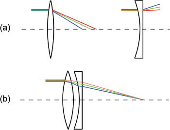
FIGURE 8.3. (a) The refraction of light by positive and negative lenses; (b) The combination of a positive lens with a negative lens having a higher index of refraction to produce an achromatic compound lens.
An achromat is a lens that has been corrected so that it has the same focal length at two wavelengths, usually in the blue and red regions of the spectrum. Lenses that have been corrected, perhaps with three elements, to give identical focal lengths at three wavelengths, and to provide some spherical correction as well, are called apochromats. However, the best color corrected lens is the superachromat, which gives perfect focus simultaneously at four wavelengths of light and often into the infrared region as well. This near perfect correction requires the use of expensive low dispersion optical materials.
8.3 The Petzval Sum
The great lens designer Rudolf Kingslake said, “The design of any photographic lens is dominated by a certain mathematical expression known as the Petzval sum.” He was referring to the specification of the image curvature that is produced by any simple or compound lens. This curvature, illustrated in Figure 8.4, is such an obvious characteristic of a simple lens that some opticians do not even regard it as an aberration.
This curvature is, in fact, a unique kind of aberration because it does not depend on the aperture or other characteristic distances in compound lenses. It does, however, depend on the focusing powers of the optical surfaces, and in 1839 Joseph Petzval (1807–1891) derived an equation for the field curvature expected from a compound lens with a number of optical surfaces in the absence of other aberrations. He used the fact that the inverse of the image curvature (1/Rp) resulting from the ith surface of an optical element is proportional to the focusing power of the surface defined as Pi = (ni – ni–1)/Ri where ni and ni–1 are the refractive index before and after the surface and Ri is the radius of curvature of the surface. Petzval showed that the curvature for the image plane resulting from all the lens surfaces is given by the summation

FIGURE 8.4. An illustration of image curvature.
where na is the refractive index of the last medium.1 When one says that the Petzval sum for a lens is large, they are just saying that the image curvature is large. Of course, the aim is to make the Petzval sum as close to zero as possible by a combination of positive and negative surface powers.
8.4 Optical Materials
Agood material for a lens must not absorb light in the visible region, but it also must have a refractive index greater than one – and the higher, the better. Of course, all materials absorb some light, and, if the thickness is great enough, the absorption will be evident. The normal situation in optics is for the refractive index to increase as the wavelength of light decreases so that the index of blue light is greater than that of red light. This effect was modeled by the mathematician Augustin-Louis Cauchy in 1836, and in 1871 his empirical equation was improved by W. Sellmeier to obtain the equation still used to characterize optical materials.5 This equation relates the refractive index to the wavelength by means of empirically determined constants:
| (8.1) |
Here n(λ) indicates that n depends on the wavelength of light λ, and the B and C coefficients are used to describe optical glasses in the standard (Schott) catalog of glasses.
Optics catalogs also characterize the dispersion of materials by means of a standard parameter known as Abbe’s number, vD.6, 7, 8 This parameter is widely used although it is a rather crude measure of dispersion. The definition is
| (8.2) |
where nD, nF, and nC are the indices of refraction at the wavelengths of the Fraunhofer lines helium D (yellow, 589.2 nm), hydrogen F (blue, 486.1 nm), and hydrogen C (red, 656.3 nm), respectively, that are found in the spectrum of the sun. In some treatments mercury (Hg) lines and cadmium (Cd) lines are substituted, but the wavelengths are not much different. In the definition of vD the numerator is a measure of the refractivity while the denominator is proportional to the dispersion.9
The most commonly used optical glasses are crown (vD ~ 60, n ≈ 1.5) and flint (vD < 55, n ≈ 1.7). The problem is that the dispersion tends to be large for glasses that have large refractivities. This is evident from the Sellmeier equation. Absorption wavelengths are usually in the UV part of the spectrum; and, when an absorption wavelength is close to the visible region, both the value of the refractive index and the rate of change of the index with wavelength tend to be large. The Schott glass company has published plots of refractive index versus the Abbe number so that lens designers can select appropriate glasses. Basically, one can easily get high refractivity or low dispersion, but not both.
As with the problem of spherical lens shapes, one must live with the limitations imposed by nature. As previously noted, one way to minimize color fringing (chromatic aberration) is to play off different kinds of glass against each other. Another possibility is to search for natural and synthetic materials that push the limits of the Sellmeier equation by providing low dispersion with acceptable refractive indices. This could result from a fortunate set of absorption frequencies. For example, crystals of fluorite (CaF2), which has vD = 95 and nD = 1.43, occur naturally but can also be grown for use in lenses. Ernst Abbe was the first person to use fluorite to enhance chromatic correction in microscope lenses in the 19th century. Fluorite is unfortunately difficult to work with, and its refractive index is so low that lens elements must be thick and heavy. So lens makers have turned to proprietary engineered glasses that are claimed to have low dispersion and fairly high refractive indices. For example, we find Hi-UD (Canon), ED (Nikon), AD and LD (Tamron), and SLD (Sigma) low dispersion glasses advertised for new lenses.
A discussion of corrections for chromatic aberration would not be complete without mentioning diffractive optics. The diffraction effect from a concentric lattice of transparent plates, as in a Fresnel lens, disperses red light more than blue – exactly the opposite of a glass prism or lens. So the idea is to use both diffractive and dispersive lens elements in a compound lens to compensate for chromatic and possibly other aberrations. Thus a lens element is introduced that has a diffraction grating etched into it. Early work in this area was delayed by problems with excessive diffraction based flare, but now Canon has developed multilayer diffraction optics, or Diffractive Optics (DO), that are competitive at least for telephoto lenses. The primary advantage appears to be more compact and lighter lenses. For example, the Canon 400 mm F/4 DO IS lens is claimed to be reduced 37% in length and 31% in weight from a comparable lens designed only with refractive optical elements. Nikon has a competitive technology known as Phase Fresnel (PF) that appears to be similar to diffraction optics. At this time, only Canon and Nikon offer lenses incorporating diffraction or Fresnel optics. Now, on the horizon we see thin optical components that promise thin lenses with no chromatic aberrations. This depends on an engineered wavelength-dependent phase shift provided by an achromat metasurface (see Section 9.7).10
8.5 Anti-Reflective Coatings
It turns out, with current technology, that compound lenses incorporating many elements are required to correct the various aberrations; and commercially available modern lenses bear witness to this requirement. Samples from lens catalogs show lenses with large numbers of elements. Also, low dispersion glass and aspheric elements are used in crucial positions to improve performance. For example:
Canon EF 100–400 mm f/4.5–5.6 L IS II, 21 elements in 16 groups (fluorite and Super UD-glass elements)
Sigma 120–300 mm f/2.8 DG OS HSM | S, 23 elements in 18 groups (SLD and FLD elements)
Nikon 80–400 mm f/4.5–5.6 ED AF VR AF-S Nikkor, 20 elements in 12 groups (4 ED and 1 super ED element)
The modern multi-element lens is only possible because of a technological breakthrough that I have not yet discussed. In the 19th century, lenses with more than four air/glass surfaces suffered from low contrast. Some lenses with six glass/air surfaces were considered acceptable; but the eight air/glass surface lenses, while better corrected for aberrations, were found to yield images with very low contrast. The problem was the reflection of light at the surfaces. When light passes from a region with the refractive index n1 to a region with the refractive index n2 a fraction R of the intensity is reflected. Equations for R were worked in the early 19th century by Augustin-Jean Fresnel. In the limit that the incident light is normal to the surface, he found that:
| (8.3) |
Here r and R are associated with the amplitude and the intensity of the reflected light, respectively. (The amplitude r refers to the electric field of light, and it will be needed to explain the effect of lens coatings.) For example, at an air/glass interface with n1 = 1 and n2 = 1.5, the fraction of reflected intensity is R = 0.04 or about 4%. This fraction is lost at every air/glass surface, so with four surfaces about 15% is lost and only about 85% of the incident intensity is transmitted. This was, indeed, a serious and disabling problem for lens technology. Light was not only lost, but the reflected light bounced around inside the lens, producing ghosts, flare, and a general loss of contrast in the focused image.
The solution to the problem lies in sophisticated anti-reflection coatings. Everyone with a camera has, of course, observed the beautiful violet and pastel shades that are reflected by several elements in the lens. The reflections from lenses manufactured in different time periods are shown in Figure 8.5.
The colors reveal coatings that are themselves colorless. Nevertheless, these coatings increase the transmission of a broad range of frequencies in the visible spectrum while reflecting a small amount of light that has not been completely cancelled by interference. The discovery of the effects of lens coatings has an interesting history. Isaac Newton observed the “colours of thin transparent bodies” in 1672–1675 and reported his finding in the second book of Opticks (1704). He knew about missing reflections associated with half-wavelengths, but his ideas are very hard to follow, and there were no practical applications. However, in the nineteenth century, with the invention of photography and advances in optics, the time was right for anti-reflective optical coatings. The early days of optical coating has been reviewed in a delightful article by Angus Macleod.11 The beneficial anti-reflecting property of coatings was accidentally discovered several times by famous scientists. For example, in the early 19th century Joseph von Fraunhofer observed the reduction of reflection from glass that was tarnished by acid treatment. Lord Rayleigh (1886) noted that old lenses (aged glass) transmitted light better than new (clean) lenses, and suggested the presence of a surface layer with a lower refractive index than the glass. So the idea that “age coated” as well as intentionally tarnished lenses were preferable to those with bare air/glass surfaces was floating around by the 1890s. Apparently, the first person to attempt the commercial use of coated glass was Dennis Taylor, who patented the use of various chemicals to deliberately tarnish optical surfaces in 1904. Unfortunately, Taylor’s results were inconsistent, and coating development lagged until the 1930s.
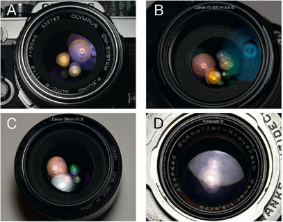
FIGURE 8.5. Reflections of a 5000K lamp from various lenses. (a) Olympus 50 mm f/1.8 (1972), (b) Canon 70–300 mm f/4–5.6 (2006), (c) Canon 50 mm f/1.8 (1987), and (d) Schneider-Kreuznach 75 mm f/3.5 (1953).
The next breakthrough occurred in 1935 in Germany when Alexander Smakula at the Zeiss company developed a method for coating lens surfaces in a vacuum with an evaporated layer of low index material. At about that time optics research became part of the war effort, and developments were classified. By 1941 the transmission of light by multi-element lenses had been improved by about 60%; and anti-reflection coatings were being ordered for periscope and binocular lenses. Macleod notes that coated binoculars permitted an extra 30–45 minutes of viewing time at dusk and dawn. Also, multi-layer coatings were being developed in Germany, and by the end of the war optical coating was a big business.
Since World War II, multilayer coatings have been developed to both enhance and diminish reflection, select wavelengths for transmission or reflection, polarize light, split beams, etc. A major driving force for the improvement of optical coating technology has been the development of lasers. Gas lasers, e.g. the He-Ne laser, especially require highly reflective multilayer coatings for mirrors. Of course, photographers benefit greatly from the availability of multilayer coated lenses. To quote Rudolf Kingslake, “The discovery of antireflection coating of lenses opened up the whole field of multi-element optical systems, so that now almost any desired number of air spaced elements can be used without danger of ghosts and flare. Without such coating all of the modern zoom and other complex lenses would be impossible.”
Now for the science.12 How do anti-reflection coatings work? Suppose a thin transparent coat with a refractive index of n1 = 1.25 is applied to a glass lens that has the refractive index n2 = 1.5. According to Equation (8.3), the fraction of intensity reflected at the air/coat surface is 1.2%, and the fraction reflected at the coat/glass surface is 0.83%. Now the important question is how to obtain the total transmission, and the numbers we have calculated are not helpful at all! Experiments show that the total reflection depends critically on the thickness of the layer. Transmission and reflection from thin layers are interference phenomena, and amplitudes of the electric fields must be combined before squaring. The amplitude of a reflected wave, which should be thought of as the length of an arrow (vector), is given by r (not R) in Equation (8.3) and each arrow has an orientation. This idea is discussed in Appendix B. A single layer anti-reflective coating is illustrated in Figure 8.6. (The arrows in this figure indicate the directions of light rays and the associated amplitude arrows denoted by the r’s are different things.)
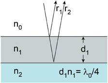
FIGURE 8.6. Single layer anti-reflective coating with exaggerated angle of incidence.
Suppose that n0 = 1 (air) and n2 = 1.5 (glass). The coating layer must have a refractive index less than 1.5 (for there to be the same change in phase angle or turn of the amplitude arrow at the two surfaces); and, for effective cancellation of reflection, it is necessary that r1 = r2 and that their orientation be exactly opposite. This condition can be combined with the equation for r to show that the optimum refractive index for the layer is n1 = √n0 n2, or in this case 1.22. We have a situation in which there are two ways for a photon to get from the source to the observer, and according to the ideas in Appendix B each of the paths can be represented by an arrow with a length and an angle. These arrows must be determined, added together, and the resultant arrow length squared in order to determine the intensity of the reflected light.
The lengths of the arrows are essentially equal because of the choice of n1, and the difference in orientation (angles) depends only on the difference in the optical path lengths. The orientation of the arrow associated with r1 (path 1) is arbitrarily set at 12 o’clock, and the orientation of the arrow for path 2 is different only because of the time required for the photon to traverse the layer of thickness d1 twice with the effective speed c/n1. A complete rotation of the arrow through 360° occurs each time the path length increases by one wavelength; and with our choice of layer thickness, the arrow for path 2 is oriented at 6 o’clock or 180° out of phase with the arrow for path 1. The two arrows, when placed head to tail, add to zero; and there is complete cancellation of the reflected light at the wavelength λ0. Since the sum of the intensities of the reflected and transmitted light must equal the intensity of the incident light, this coating permits 100% of light at λ0 to be transmitted. I have simplified things here by assuming that the angle of incidence is close to zero, the amplitudes of reflection are very small, and by neglecting multiple reflections in the layer. Corrections for these simplifications do not change the qualitative picture.
Of course, things are far from perfect, because the single layer is only efficient at cancelling reflection at one wavelength. With a two-layer coating it is possible to zero out reflection at two wavelengths, a three-layer coating can be designed to cancel reflection at three wavelengths, etc. Approximate analyses of these situations are quite easy with the vector method summarized here.
However, there is still a serious problem, because multi-coated surfaces begin to lose their effectiveness for light at large angles of incidence. Accordingly, reflections from high curvature lenses produce flare and ghosting. Reflections from the surface of sensors also contribute to this problem. One way to ameliorate this problem is to turn to lens coatings that mimic the surface of the corneas of some insect eyes. In particular, the cornea of a moth eye shows low reflectivity because of patterned microstructures on its surface. The idea is that subwavelength structures with cone or pyramid shapes can form a layer with much lower average density at its surface than at its base. One can picture a forest of tapered needles. This provides a refractive index gradient ranging from perhaps 1.0 to 1.5 that gives a smooth transition from air to a glass lens element.13
Subwavelength structure coatings (SWC) are now available on some lenses from Canon, Inc. The coating of large curved surfaces with microcrystalline alumina (Al2O3) films is possible through the use of sol-gel solutions. After drying, the films are random and complex; but they have the necessary thickness and properties. If the maximum refractive index does not equal that of a glass lens element, an intermediate layer may be necessary. Tests show that SWC lenses have lower reflectivity over a wider wavelength range than conventional multi-coated lenses. Also, ghosting is largely eliminated in demonstration photographs.
8.6 Conclusion
Iset out to show why modern lenses are so complicated. That should be evident by this point. But, it should be noted that the discussion thus far applies to fairly simple “prime” or non-zoom lenses. Also, most modern lenses contain autofocus mechanisms and in some cases vibration isolation systems based on the movement of a lens element to counteract low frequency vibrations. These important technological refinements are beyond the scope of this book, but some of the optical characteristics of compound lenses, e.g. primary surfaces and nodal points, will be considered in later chapters.
Futher Reading
Kingslake, R. (1951). Lenses in Photography. Rochester, NY: Case-Hoyt Corp., chap. 4.
http://en.wikipedia.org/wiki/Main_Page. Gateway to most of the terms used here. For the most part it is reliable for scientific information, but use with a critical eye. When in doubt check other sources.
Notes
1. Kingslake, R. (1989). A History of the Photographic Lens. New York: Academic Press, Inc. chap. 1.
2. Klein, M. V. (1970). Optics. New York: Wiley, chap. 4.
3. Photographic optics with illustrations of Seidel aberrations: http://www.vanwalree.com/optics.html
4. Canon, Inc. (2003). EF Lens Work III, The Eyes of Canon.
5. The Sellmeier equation was given a reasonable theoretical foundation by the Dutch physicist Hendrik Lorentz in 1892 (Drude-Lorentz theory) in terms of oscillating electrons in the electric field of light rays. Of course, our view of light and matter changed completely with the discovery of quantum mechanics. The translation of Lorentz’s equation into quantum language was performed by John van Vleck (1925) and by Hans Kramers and Werner Heisenberg (1926). The latter paper, co-authored by Heisenberg, is credited with leading directly to his discovery of quantum mechanics (matrix mechanics), which was published shortly thereafter. The modern interpretation of the Sellmeier equation is as follows. The major dependence of the index function n(λ) on wavelength λ results from absorption of light at the wavelengths λ1 = √C1, λ2 = √C2, and λ3 = √C3. The contributions to n(λ) of the absorptions at λ1, λ2, and λ3 are determined by the coefficients B1, B2, and B3 respectively. These coefficients are related to the strengths of the absorptions and can, in principle, be computed by the methods of quantum mechanics. Each absorption is associated with the transition of an electron from its ground energy state to a higher energy state. For example, in the transition at λ1, a photon of light with energy hv1 is absorbed by an electron to produce the energy change ∆E = hv1 = E1excited – E1ground.
6. Glossary and Optics Guide: www.mellesgriot.com, http://www.astro.caltech.edu/~lah/ay105/pdf/Fundamental-Optics.pdf
7. Innovation 15, Magazine from Carl Zeiss, A tribute to Ernst Abbe: http://www.science.marshall.edu/dneff/nobel_etc/earnst%20abbe.pdf
8. Dispersion and other things: http://hyperphysics.phy-astr.gsu.edu/hbase/geoopt/dispersion.html
9. The lens maker’s equation shows, that for a given lens, the quantity f(n – 1) is a constant. The application of differential calculus immediately relates the fractional change in focal length f to the change in refractive index n: δf / f = –δn/(n – 1). Here δf and δn represent the changes in the focal length and the refractive index, respectively. The right-handside of this equation is known as the dispersive power of the material and the Abbe number is just an approximation to the inverse of this quantity.
10. Aieta, F., Kats, M. A., Genevet, P., and Capasso, F. (2015). Multiwave Achromatic Metasurfaces by Dispersive Phase Compensation. Science, 347(6228), pp. 1342–1345.
11. Macleod, A. (1999). The Early Days of Optical Coatings. Journal of Optics A: Pure and Applied Optics, 1, pp. 779–783.
12. Heavens, O. S. (2011). Optical Properties of Thin Films, 2nd Ed. New York: Dover Publ.
13. Okuno, T. (2010). Development of Subwavelength Structure Coating (SWC) and its Application to Imaging Lenses. Proceedings of SPIE-OSA 7652, 765203-2.