APPENDIX B
What Is Behind the Rules of Optics?
You will have to brace yourselves for this—not because
it is difficult to understand, but because it is absolutely
ridiculous: All we do is draw little arrows on a
piece of paper—that’s all!
—R. P. FEYNMAN
A lways in science we look for unifying concepts and general theories. Light is an electromagnetic wave, so it should be described by Maxwell’s theory of electromagnetism. But now we can go beyond that description and predict light intensity and the interaction of photons with electrons by means of quantum electrodynamics (QED). QED is a model of the world that is totally unfamiliar to most of us, but it is easy to see how it works without using advanced mathematics. R. P. Feynman, one of the founders of QED, explained in detail the basic ideas and how to use them in his beautiful little book QED, The Strange Story of Light and Matter. This brief appendix is an introduction to Feynman’s ideas. It is thinly disguised graduate level physics. I hope it will motivate serious science students to explore this topic through further reading.
What we want to know is how light gets from a source to a detector such as those in the sensor of a digital camera. We know it has to do with waves and their interference. Fortunately, it turns out that a light wave can be represented by a rotating arrow (vector)—think of the hands of a clock. The important things to keep up with are the length (amplitude) and turn (angle) of the arrow. Each way that a photon can go from place to place is described by a single rotating arrow. Feynman proposed a set of rules for dealing with these arrows that permit us to compute the outcome of any optics experiment. He tells us not to worry about understanding them, just learn to use them, because they describe the way nature behaves. So here they are:
1. If an event can happen in alternate ways, determine the arrows for each way and then add them by placing them head to tail. The “sum” is obtained by drawing an arrow from the tail of the first arrow to the head of the last arrow.The length of this final arrow is called the “probability amplitude.”
2. The probability of the event is determined by squaring the probability amplitude.
What this says is that photons take every possible path, not just those specified by Hero’s law of reflection, Snell’s law of refraction, etc. However, when the little vectors for all of the paths are added up and the sum is squared, there is little probability that a photon will violate the well-known laws of optics. This is known as Feynman’s sum-over-paths quantum theory, and it is consistent with the rules of optics and much more. The procedure, not why it works, can be understood by looking at some examples. First, consider photons of red light going from a Source at S to a Detector at D as shown in Figure B.1. The wall between the source and the detector has two very small holes (slits) that are located at A and B. The holes are so small that the normal laws of optics do not work (diffraction effect). We start the clocks when the photon leaves the source and the clock hands (little arrows) rotate at the frequency of light until the photon reaches the detector. A photon moves at the speed of light, so the orientation of the arrow will depend on the length of the path if nothing else happens along the way. Since the two paths have different lengths, the travel times and the rotation angles will be different.
FIGURE B.1. The two slit experiment.
Here is what happens. When the hole at B is blocked, the detector measures some light intensity, e.g. 100 photons per second. This is perhaps 1% of the photons that leave the source. The arrow representing this path has some direction, say 2 o’clock, and the length 0.1. With only a single arrow, the direction does not matter and the length squared gives 0.01 as the probability of detecting a photon. If B is open and A is blocked, the same intensity is detected as when only A was open. The arrow for the path through B has a direction, say 3 o’clock, and the length is again 0.1. Now for the good stuff. When both holes are open, the intensity can be anything between 0% and 4%; and it depends on the separation of the holes as well as the frequency of the light. The exact number must be computed from the arrows. According to the rules, we connect the arrows and determine their sum. (See Figure B.2.)
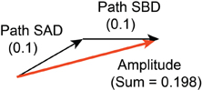
FIGURE B.2. The sum of arrows (vectors) for two paths.
In this case, with arrows at 2 o’clock and 3 o’clock, we find that the amplitude squared is 0.1982 or about 3.9%. This procedure can be repeated for different heights (vertical position) of the detector to map out the intensity pattern for the double-slit experiment.
The reflection of light from a mirror, discussed in Chapter 6, provides another illustration of the sum-over-paths method. As shown in Figure B.3, light from the source can reach the detector by reflecting from any point on the mirror - though here we only consider a thin strip of mirror sticking out of the page. The length of each path is given by Equation (6.2), and the time required for the journey can be obtained by dividing the path length by the speed of light, c = 2.997 × 10⁸m/s. The result of this calculation is shown at the bottom of Figure B.3 for each reflection point. In this illustration the length of the mirror is L = 10 cm and a small section centered on x = 5 cm has been greatly magnified to show the clock angles for a region about 600 µm long. When the small arrows are added, the length of their sum is found to be determined by a few arrows in the center. It would not change significantly if more arrows were added at the ends because they would only continue to go in circles. Note that the spiral formed by the arrows is just the Cornu spiral found in optics textbooks. So the probability is nonzero for reflection from the vicinity of the point where the angle of incidence equals the angle of exit. This agrees with Hero’s law and Fermat’s principle of least time. It is, however, more general, since it correctly handles cases where the maximum time path is chosen, e.g. reflection from an elliptical concave mirror.
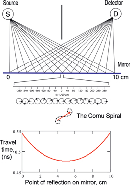
FIGURE B.3. Reflection of light with wavelength λ = 550 nm from a mirror. The length of the mirror is 10 cm and the source and detector are located above the left and right ends of the mirror, respectively.
There is still more to recover from the sum-over-paths analysis of reflection. Suppose we chop off all of the mirror except the piece from x = 0 to x = 2 cm. We know that no light from that region is reflected to the detector, but it is still worthwhile to look at it in detail. If we take the angle of the arrow for reflection from x = 1 cm as the reference angle and examine the other angles for reflection in that vicinity, we find the result shown in Figure B.4. Every 0.4 µm (400 nm) the orientation changes by 180°, and so the amplitude for reflection completely cancels out for that region, i.e. the arrows add up to zero. However, the diagram suggests how the reflection can be recovered. All we have to do is to scrape away the mirror at the positions where the arrows are aimed down! Actually, 3 o’clock to 9 o’clock. When we add up the remaining arrows and square the sum, we find that the probability is large for reflection of 500 nm light to the detector. What we have done is to create a diffraction grating. When white light is used as the source, each wavelength (color) diffracts strongly at a different angle as shown by reflection from the CD in Figure 2.4.
These examples show the origin of the rules of optics at a fundamental level including, when appropriate, Fermat’s principle of least time. However, there are still some questions about the interaction of light with matter that results in reflection, transmission, and refraction. The angle for each rotating vector depends on the total transit time through a lens or collection of lenses including the time inside glass where the refractive index differs from unity. Other things can happen along the way, as well, and the interaction of light with matter (more precisely photons with electrons) requires a few more rules. To handle reflection from a sheet of glass, when some of the incident light is transmitted, the arrow for the reflected light must be reduced in length so that its square equals the probability of reflection. Also, the process of reflection (from air back to air) reverses the direction of the arrow, i.e. gives a phase shift of 180°. This reversal of direction also applies to the mirror we considered above, but in that case the reversal did not affect the result since it applies to every arrow. The phase reversal is essential, however, for dealing with sheets of glass where light can reflect from more than one surface, and the arrows for paths with different numbers of reflections have to be added. Another rule, apparent from previous comments, is that light appears to require a longer time to pass through a piece of glass than through the same distance in air, and the time in glass is approximately equal to the time in air multiplied by the refractive index.
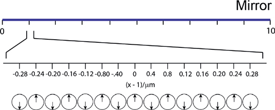
FIGURE B.4. Reflection from the end of the mirror far from the path of least time.
But now the number of rules is growing, and it is not clear where they are coming from. Actually, things are not as bad as they might seem. The phase shift on reflection and the refractive index are, in fact, the results of calculations involving all the atoms in the glass. A single rule specifies the scattering of a photon by an atom. The arrow shrinks by an amount that depends on the kind of atom and also turns by 90°. I am not going to complete these calculations, but simply tell you that when the arrows for the photons, scattered from all the atoms, in the direction of reflection, are added, the result is a wave at the surface of the glass that can be described by an arrow appropriately reduced in length and with a reversed direction. This same model of scattering of photons by atoms also produces a transmitted light wave that can be described by an arrow with exactly the same orientation as would be calculated by assuming that the velocity of light inside the glass is reduced by the factor n. A detailed discussion of these calculations can be found in the Further Reading references.
All of this stuff about rotating arrows is just a way to approximate the final quantum mechanical wavefunction. Of course, quantitative calculations require the summation of very many closely spaced paths and, in fact, integral calculus must be used. The simplified diagrams and computations presented here are designed to reveal the basic ideas rather than to provide tools for exact computation.
Futher Reading
Feynman, R. P. (1958). QED: The Strange Story of Light and Matter. Princeton: Princeton University Press
Taylor, E. F., Vokos, S., O’Meara, J. M., and Thornber, N. S. (1998). Teaching Feynman’s Sum-Over-Paths Quantum Theory. Computers in Physics, 12(2), pp. 190–199.