Chapter 10: Rendering Sculptures for Your Portfolio
We've worked hard to learn many interesting sculpting tools, tips, and techniques, and now we've got some awesome sculptures to show off in our portfolios! But before we upload any images of our artwork for the world to see, we should make sure that our sculptures can be seen in the best light – literally! We should add lights to the scene and set up materials for the sculptures so that they look amazing! Once we have our lights in place, we can render the artwork.
Rendering is what our computers do to calculate the appearance of 3D objects in the scene. Rendering can be done with varying quality, depending on our needs. Technically, our computers are always rendering our sculptures into the 3D Viewport. Viewport rendering is usually done with relatively low-quality settings so that our computers' processing power can be dedicated to the sculpting tools instead of the rendering process.
We learned a little bit about how Blender draws objects in the 3D Viewport in the Exploring the viewport shading modes section of Chapter 1, Exploring Blender's User Interface for Sculpting. We know that Solid mode with MatCap shading works well while we sculpt because this mode prioritizes fast sculpting performance over visual quality. However, this shading mode doesn't look the best for presenting a finished piece of art. This is where the Rendered shading mode comes in.
When we use the term render, we typically aren't referring to the solid viewport shading mode. Instead, we use the term to refer to the highest quality type of rendering that is used for producing the final image after we've created all of the 3D objects. This is the type of rendering that we will learn to do in this chapter.
The main topics in this chapter are as follows:
- Setting up Rendered mode
- Adding three-point lighting to the scene
- Lighting up the environment with an HDRI
- Creating a clay material for the sculpture
- Using a camera to render the sculpture
- Setting up a turntable for a 360-degree render
- Exporting the final render
Technical requirements
For general requirements, refer back to the Technical requirements section laid out in Chapter 1, Exploring Blender's User Interface for Sculpting.
You can download the files to follow along with this book at the GitHub link here: https://github.com/PacktPublishing/Sculpting-the-Blender-Way.
This chapter will rely more heavily on your graphics card than any of the previous chapters because rendering is a task typically performed by the graphics card. The Blender Foundation has made efforts to support as many graphics cards as possible. However, some rendering settings are limited by your operating system and graphics card manufacturer. GPU rendering on macOS is currently not supported, so you will have to use CPU rendering instead, which tends to be slower. GPU rendering support on macOS is in the works, with a target release in Blender 3.1; you can follow the development of this feature here: https://developer.blender.org/T92212.
Another small limitation is that some denoising features such as the OptiX AI denoiser are only available on NVIDIA graphics cards. For a better understanding of which rendering features your computer supports, you can read more here: https://docs.blender.org/manual/en/latest/render/cycles/gpu_rendering.html.
You will be able to follow along with this chapter with most computers, but some parts of the rendering process may take much longer than normal if your computer doesn't support GPU rendering and denoising.
Setting up Rendered mode
Rendering is the highest-quality way to view our sculptures, but it is also the slowest way for our computers to draw 3D objects. This trade-off is worth it as long as we choose the appropriate settings that will make our renders look good.
The first thing we need to understand is that the process of rendering is performed by a render engine. Blender is not a render engine; we use Blender to sculpt and model our 3D objects, but when it's time to render, we need to choose which render engine to use. This is typical of all 3D software; it's not a problem for us because there are many render engines to choose from. Blender includes two render engines out of the box, Eevee and Cycles.
- Eevee is a real-time rasterizing render engine that prioritizes fast speed over realistic lighting. A render from this type of render engine usually takes less than one second to process. This is most closely comparable to high-quality video game graphics. The results from this type of render engine can look really fantastic. However, certain shortcuts are taken to keep the render engine working fast, which means the lighting isn't as realistic as other engines. You can read more about the Eevee render engine here: https://docs.blender.org/manual/en/latest/render/eevee/introduction.html.
- Cycles is a path tracing (a type of ray tracing) render engine that prioritizes realistic light calculations over speed. A render from this type of render engine usually takes a few minutes or sometimes hours to process. This type of render engine is typically used in professional animated movies. If you want the absolute best quality possible and you want precise artistic control over the quality of the lighting, this is the best type of render engine to use. You can read more about the Cycles render engine here: https://docs.blender.org/manual/en/latest/render/cycles/introduction.html.
Important Note
At the time of writing this book, the Blender Foundation is preparing to release Blender 3.0. This upcoming version of Blender includes an updated version of Cycles (internally known as Cycles X). Render times are much faster in this updated version. We recommend using this new version of Blender if you choose to render your sculptures in Cycles. You can read about the Cycles X improvements here: https://code.blender.org/2021/04/cycles-x/.
Both of these render engines are fairly easy to get started with. In this section, we will learn how to tell Blender which render engine we want to use and how to set up the render settings to take advantage of our graphics card.
Getting ready
For this section, we're going to use one of our previous example files to help demonstrate the difference in visual quality between the Eevee and Cycles render engines. The skin, eye, and hair materials from the old monk example can be rendered in either engine, but the resulting image will be different in each engine. We'll use the realisticEyebrows_End.blend file to demonstrate these differences. You can download the file here: https://github.com/PacktPublishing/Sculpting-the-Blender-Way/blob/main/Chapter09/realisticEyebrows_End.blend.
Launch Blender and open the .blend file. Once the file is loaded, we can set up our render settings.
How to do it…
Let's start by enabling our graphics card as a Cycles render device in the user preferences:
- Open the Edit menu from Blender's Topbar and choose Preferences.
- Once the Blender Preferences window appears, click on the System tab.
- Find the Cycles Render Devices section.
Important Note
These settings will be different, depending on your computer's operating system and graphics card. There are several computation backend options here: None, CUDA, OptiX, and OpenCL.
The None option means that rendering will be performed on your computer's Central Processing Unit (CPU) instead of the Graphics Processing Unit (GPU). This will still produce high-quality results, but rendering will take much longer.
The CUDA option is a computation backend for rendering with NVIDIA graphics cards; it has a wide range of compatibility for many graphics cards.
The OptiX option is a newer backend for rendering with NVIDIA graphics cards. It has less compatibility with old graphics cards, but it renders faster than CUDA.
The OpenCL option is primarily used for AMD graphics cards. It is slower than the NVIDIA backends, but it's still faster than CPU rendering. OpenCL will no longer be supported in the upcoming Blender 3.0 release. Implementation of an alternative backend (HIP) is in development to support AMD graphics cards. Other implementations are in the works to support Intel graphics cards in the future.
If your hardware doesn't support these backends, you will see this warning: No compatible GPUs found for path tracing Cycles will render on the CPU.
- Choose the computation backend that works for your computer; we will use Optix in our example.
- Enable the checkbox for your commute device (NVIDIA GeForce GTX 1660 Ti in our example):

Figure 10.1 – The Cycles Render Devices section of the Blender Preferences window
These settings are part of Blender's user preferences, so they will be automatically saved and retained between Blender projects. You should only have to set up these options one time. You can close the Preferences window when you're finished. Once these settings are enabled, Blender will be able to use your graphics card for GPU rendering in the Cycles render engine.
Now, let's try rendering the old monk character in Eevee and Cycles to see the difference between the two render engines:
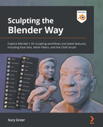
- Navigate to the Render tab (represented by the gray camera-back icon) in the Properties editor.
- Make sure that Render Engine is set to Eevee:
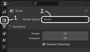
Figure 10.2 – The Render Engine option in the Render tab of the Properties editor
- Now that we've told Blender which render engine to use, we can activate the viewport render mode. Let's see what the old monk looks like when rendered in Eevee.
- Change the viewport shading to Rendered mode by clicking the fourth shading mode sphere icon in the top-right corner of the 3D Viewport:

Figure 10.3 – Rendered shading mode in the Viewport Shading options
This will tell Blender to use our choice of render engine to draw the objects in the 3D Viewport. Since we chose Eevee, the old monk will now be rendered with Eevee, as you can see in the following screenshot:
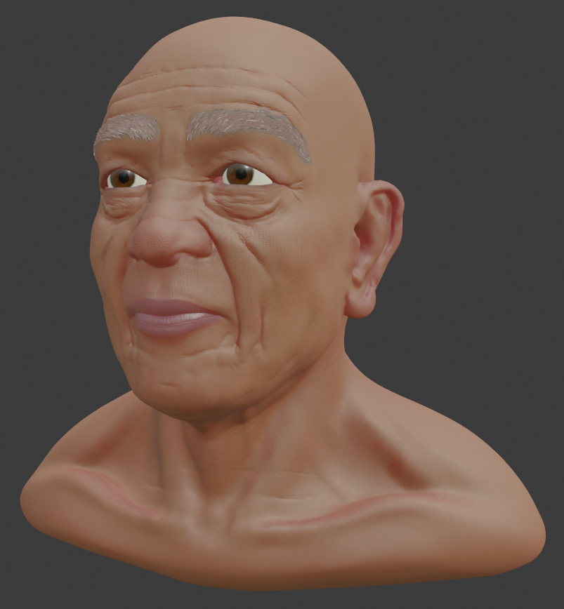
Figure 10.4 – The old monk character rendered in Eevee
If you're thinking that this looks the same as the Material Preview shading mode, you are correct. The Material Preview shading mode always uses Eevee under the hood to render the objects in the viewport without needing to switch to Rendered shading mode. This means that the render results will look the same between Material Preview and Eevee's Rendered shading mode unless we use custom lighting in the Rendered mode. However, custom lighting has been disabled for this example file, so the results are identical.
Let's try changing the to the Cycles render engine to see some very different results:
- Change Render Engine to Cycles in the Render tab of the Properties editor.
- Change the Device to GPU Compute. (The GPU Compute option will only work if you have a compatible graphics card set up in the Cycles Render Devices section of the preferences that we set up at the beginning of this section. If you do not have a compatible graphics card, you can leave the Device setting set as CPU.)
Important Note
The first time you use the OptiX rendering backend, viewport rendering might take a few minutes to start. You will see a message in the top-left corner of the 3D Viewport that says Loading render kernels (may take a few minutes the first time). This can take around five minutes to process the first time. If you don't want to wait, you can use CUDA instead of OptiX.
Once rendering begins, you will notice that the image starts off looking really pixelated and noisy, but over time, the image becomes clearer as long as you don't move the camera or any of the objects in the scene. An example of the rendering progress can be seen in the following screenshot:

Figure 10.5 – The noisy render of the old monk in Cycles
Important Note
As this is a graphically intense process, you will likely hear your computer's fans spin up to full speed. This is expected and completely normal; it will not damage your computer.
If you are using CPU rendering, your computer may slow down considerably. Basic tasks such as using an internet browser have to share resources with the rendering process, so they will likely slow down as well. It is recommended that you don't use other applications at the same time as rendering.
This slow rendering progression is a downside to using a path tracing render engine such as Cycles. The rendering has to start over each time the camera, objects, or lights are moved. However, the final result of a Cycles render is almost always of a higher quality than that of an Eevee render, as you can see in the following screenshot:

Figure 10.6 – The old monk character rendered in Cycles
Note that this render has much more accurate lighting across the surface of the character's skin. The reflections in the eyes are more realistic, the eyebrow hair has more depth, and the crevices of the skin are more appropriately dark. Other subtle details come through more clearly, such as the light penetrating the rim of the ear to give it a subtle red glow.
Both of these render engines can be tweaked to produce very pleasing results, but realistic materials and lighting are more easily achieved with Cycles. Most of the rest of the information throughout this chapter will be helpful for using both render engines; you may choose whichever engine suits your needs. We will be focusing on Cycles because it does a better job with accurate lighting, which is really important for rendering sculptures.
How it works…
Rasterizing engines such as Eevee are most common in video games. They work by converting the 3D models to pixels on our screen and running simplified shading algorithms to color each pixel. Extra features like shadows, bloom, and ambient occlusion can be added for a more complete image. However, each of these features uses shortcuts that sacrifice accuracy in order to keep the rendering happening in real time.
These days, rasterizing engines have come a long way and can produce very high-quality results. You may be completely satisfied with the renders that Eevee can produce, especially because the renders are instantaneous. However, Eevee does have some shortcomings and isn't always the best choice.
Path-tracing engines such as Cycles are considered to be the most accurate high-quality way to render. They work by casting rays of light into the scene from the camera, and then tracing the path of the light as it bounces off of each surface. The path each ray of light takes is dictated by the qualities of the materials of each surface that the light hits.
Each ray of light is calculated similarly to the way light works in real life, so the lighting looks very realistic in this type of rendering engine. However, tracing these paths of light takes a long time and a lot of processing power. Unfortunately, light that scatters around the scene often leads to image noise. Many materials have complex surfaces that require more than one path to be traced for each pixel in the final image. This means that we need additional samples to reduce image noise. This is why the image starts off really noisy and clears up over time.
We can watch as Cycles renders each path tracing sample in the top-left corner of the 3D Viewport. The more samples, the less noisy the image will be; 256 samples are used in our example file. This setting can be adjusted in the Sampling subsection of the Render tab of the Properties editor.
There's more…
Material Preview mode is closely related to Rendered mode. This mode ignores the scene lights and the environment lighting (aka the scene world) so that we can focus on developing the look of the materials before we render. A default set of environment lighting is used instead to evenly light the scene so that the objects can be seen. This can be controlled from the Viewport Shading pop-over menu by enabling the Scene Lights and Scene World settings.
It is important to know that Rendered mode requires us to set up our own lights and environment lighting settings. If we do not set these up, our renders will be very dark and not very appealing. This did not affect our example file because the Scene World setting under the Viewport Shading pop-over menu was disabled for this file ahead of time. Because of this, Blender used the default environment lighting from Material Preview mode to render instead of using the scene's custom environment lighting, which has not been set up for this file.
We will learn how to set up lights for the scene as well as environment lights in the next two sections of this chapter.
Adding three-point lighting to the scene
A major part of rendering is lighting. Without lights, our render would be completely dark, and it would be impossible to see anything. Up to this point, we've been working in Viewport Shading modes such as Solid, MatCap, and Material Preview, each of which gives us default lighting so that we don't have to worry about lights while we work on our sculptures. But now is the time to be more creative with our lighting and customize the look and feel of our finished sculpture by placing our own lights in the scene instead of using default lighting.
We can use a classic setup for lighting called three-point lighting. This type of lighting is an easy way to get started and produces high-quality results. A diagram of this lighting setup can be seen in the following screenshot:

Figure 10.7 – The typical three-point lighting setup
This involves a Key Light that lights the subject from the front; this is the primary source of light for the subject. This light is typically placed slightly above the subject, but its position can be adjusted as needed to produce alternative moods. A secondary Fill Light is used to soften the image and fill in the harsh shadows of the subject that are created by the Key Light. This light usually needs to be placed 90 degrees off from the Key Light so that it can add light to the shadowy areas. Lastly, a bright Rim Light is used from behind to help separate the subject from the background. This light is sometimes known as a back light or hair light. Without it, the subject's silhouette tends to blend into the background and feel less pronounced.
In this section, we will learn how to add lights to the scene to create this setup.
Getting ready
For this section, we can use any finished sculpture. However, some of the example files provided with this book already have lights added and render settings adjusted. Since we will be focusing on how to set up render settings from scratch, we recommend using either your own creation or the orc from stylizedEyebrows_End.blend, which you can download here: https://github.com/PacktPublishing/Sculpting-the-Blender-Way/blob/main/Chapter09/stylizedEyebrows_End.blend.
Launch Blender and open the .blend file. Once the file is loaded, we can set up our lights.
How to do it…
Let's start by adding the first light in the three-point lighting setup – the key light:
- Open the Add menu in the top-left corner of the header of the 3D Viewport and choose Light | Area.
- Rename the new light Key Light.
- Use the Move tool to place the light in front and slightly to the side of the sculpture:

Figure 10.8 – The key light in front and to the side of the sculpture
Now that we have the light in position, let's aim it at the sculpture. We could use our Rotate tool, but this light comes with a gizmo that we can use to aim it at the sculpture. There is a yellow dot in front of the area light; this dot can be dragged onto any surface to aim the light at the target surface. Let's try it now.
- Click and drag the yellow dot gizmo onto the sculpture to aim the light:

Figure 10.9 – The key light aimed at the sculpture
We can't see the effect of this light in the viewport until we switch to the Rendered viewport shading mode. You can use either Eevee or Cycles for this, but we'll use Cycles in our example.
- Navigate to the Render tab (represented by the gray camera-back icon) in the Properties editor.
Change Render Engine to Cycles.
Change Device to GPU Compute if your computer supports it.
- Change Viewport Shading to Rendered mode:

Figure 10.10 – The key light in Rendered mode
Great – now we can see the effect of the light on the surface of the sculpture. However, the light is very dark. The intensity of a light source is affected by several factors: the distance of the light to the subject, the power of the light, and the size of the light's area. In our example, the light is at a far distance, which means we need to increase the power and the size.
- With the area light selected, navigate to the Object Data tab (represented by the green lightbulb icon) in the Properties editor.
Increase the Power setting to 1500 W.
Increase the Size setting to 2 m.
Excellent – because we are mimicking studio lights, we can use really high wattage values like this to add a lot of brightness to this main source of light. The size of the light has a big impact on the sharpness of the shadows. Small lights produce hard shadows and large lights produce soft shadows:

Figure 10.11 – The key light with more power and a larger size
While we're making adjustments to the key light, we can add some color to it.
- Click on the Color swatch and use the color picker to choose a color for the key light. For our example, we went with a subtle greenish color with the hex code 9DFFD8.
Here's how our example looks so far with the colored key light:

Figure 10.12 – The orc rendered with the key light
This light acts as the main light for the three-point lighting setup. It will control the general mood of the lighting.
Tip
Feel free to try positioning this light at other angles. Moving the key light below the sculpture is a great way to make things look sinister.
The key light has left behind some dark shadowy areas. Our next step is to add a fill light to fill in these areas:
- Open the Add menu in the top-left corner of the header of the 3D Viewport and choose Light | Area.
- Rename the new light Fill Light.
- Use the Move tool to place the light in front and slightly to the side of the sculpture, opposite of the key light.
- Aim the fill light at the sculpture either with the Rotate tool or the aim gizmo.
Increase the Power setting to 500 W.
Increase the Size setting to 5 m.
- Click on the Color swatch and use the color picker to choose a color for the fill light. For our example, we went with a complimentary purple color with the hex code D495FF:
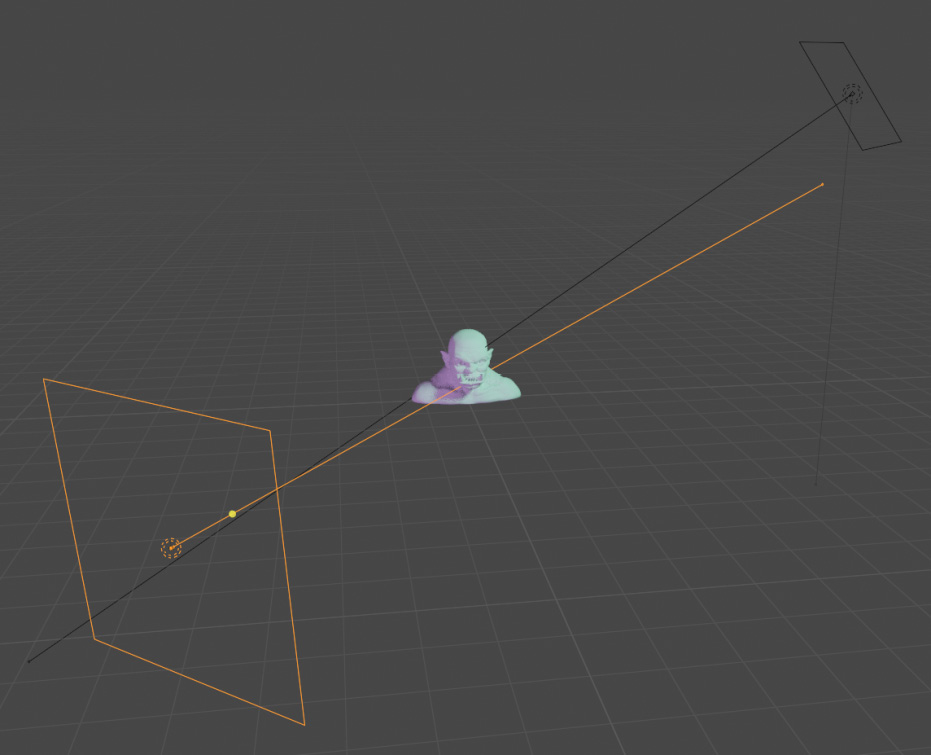
Figure 10.13 – The fill light positioned to the side of the sculpture
Here's how our example looks with the fill light added:

Figure 10.14 – The orc rendered with the key light and fill light
The fill light is much less bright than the key light. It's meant to be complementary; it shouldn't upstage the key light. Because of its large size, the fill light produces soft shadows, and it does an excellent job at filling in the hard shadows from the key light.
The final light we should add is the rim light:
- Open the Add menu in the top-left corner of the header of the 3D Viewport and choose Light | Area.
- Rename the new light Rim Light.
- Use the Move tool to place the light behind the sculpture.
- Aim the rim light at the sculpture either with the Rotate tool or the aim gizmo.
Increase the Power setting to 3000 W.
Leave the Size setting set to 1 m.
- Click on the Color swatch and use the color picker to choose a color for the rim light. For our example, we went with a strong deep blue color with the hex code 3400FF:

Figure 10.15 – The rim light positioned behind the sculpture
Here's how our example looks with the rim light added:

Figure 10.16 – The orc rendered with the key light, fill light, and rim light
The rim light is typically the brightest light in the scene; it casts a bright light across the back of the sculpture, creating a rim of light that helps to make the sculpture stand out from the background.
To keep our .blend file organized, let's add all of the lights to a collection:
- Select all three lights.
- Open the Object menu in the top-left corner of the header of the 3D Viewport and choose Collection | Move to Collection.
- A small window labeled Move To Collection will appear under your mouse cursor; click the + New Collection button.
- Name the new collection Lights and click the OK button.
And that's all there is to the three-point lighting setup. This setup can be modified as much as you like to produce a different look for your sculpture.
How it works…
Blender's lights closely mimic real lighting, so we can use real-world techniques to produce lighting for our sculptures. Three-point lighting is one of the most tried and true types of lighting in professional media production. It's far from the only way to light a subject, but it produces high-quality results with ease.
There's more…
In this section, we used only one type of light, but Blender offers four main types of lights:
- Point: A point light is similar to a small light bulb; all of the light comes from a single point in 3D space and emanates outward in all directions.
- Sun: This is a directional light; its position in 3D space is ignored. All light from this type of light is parallel and closely simulates the light from the sun; it is useful for filling the scene with light the way the sun does in real life.
- Spot: This light produces a cone of light exactly like the lights used in theater. It is excellent for creating a dramatic look.
- Area: This type of light emits from a large surface area and closely mimics studio lights. It is excellent for adding lots of light and giving fine control over the hardness of the shadows that it produces.
When you're comfortable with the basics of setting up lights, feel free to experiment with some of these other light types to customize the look of your renders.
See also
The Blender Foundation has an official video showcasing a three-point lighting setup, available here: https://www.youtube.com/watch?v=RDbrOpnIY7Q.
Lighting up the environment with an HDRI
There is an additional type of lighting for our scenes that we need to consider when creating high-quality renders – environment light. This type of light is present in the scene without being tied to a specific light object in the Outliner. There are two main types of environment light that we can use. The first type is known as ambient light. This is a basic type of lighting that adds brightness to the entire scene evenly. By default, Blender has a small amount of ambient light enabled. However, this type of lighting isn't used very often in modern renders because it's not a realistic way to light a scene. The most realistic and popular way to add environment lighting is through the use of a High Dynamic Range Image (HDRI).
An HDRI is a spherical 360-degree image of an environment that contains an incredibly large amount of lighting information in each pixel. These images are usually created with a special photography process that captures what an environment looks like at numerous exposure levels, and then stores all of the data in a single image that we can control with our 3D software. HDRIs are typically stored in the .hdr or .exr file formats. It's important to know that these files are not interchangeable with regular images that have been stored in the following image formats: .png, .jpg, .tga, .tiff, and other non-HDR formats.
In this section, we will learn how to load an HDRI into Blender's world properties, which will allow us to use the realistic lighting information from the image to cast light into the scene and onto the surface of our sculpture.
Getting ready
For this section, we can pick up where we left off in the Adding three-point lighting to the scene section of this chapter. If you have not completed that section, you can begin this section with the threePointLighting_End.blend file, which can be downloaded here: https://github.com/PacktPublishing/Sculpting-the-Blender-Way/blob/main/Chapter10/threePointLighting_End.blend.
We will also need an HDRI to add to the environment. We have provided one for you to use, which can be downloaded here: https://github.com/PacktPublishing/Sculpting-the-Blender-Way/blob/main/Chapter10/phalzer_forest_01_4k.exr.
Launch Blender and open the .blend file. Once the file is open, we can set up the environment lighting for the scene.
How to do it…
Environment light is part of the World properties tab of the Properties editor. However, controlling the HDRI is done through the Shader editor. This is a special type of editor that will allow us to connect nodes together to control the lighting and materials. This editor is not present in the current workspace, so let's start by changing over to the Shading workspace:
- Click on the Shading tab at the top of the user interface:

Figure 10.17 – The Shading workspace tab
Important Note
The available workspaces will be different depending on how the file was created. Our example file was created from the sculpting preset, so it includes the Sculpting and Shading workspaces. If you do not see the Shading workspace tab, you can add it by clicking + and choosing General | Shading.
Clicking on this tab will rearrange the entire user interface with new editors and a layout that is suited for setting up the environment lighting. This workspace includes six editors, as you can see in the following screenshot:

Figure 10.18 – The six editors in the Shading workspace
There are several new editors available to us in this workspace:
- The File Browser will allow us to browse for texture files, such as the HDRI that we've downloaded for this project. Alternatively, you can use your operating system's file browser, but Blender includes this editor so that you never have to leave Blender's UI to browse for files.
- The Image editor gives us a preview of our image and texture assets that we've loaded into Blender. We can also use this editor to paint textures, but that's beyond the scope of this book.
- The Shader editor is our main focus for this section. This allows us to create a network of nodes to customize our environment lighting and materials for our sculptures.
This workspace also includes three editors that we have used previously in our other workspaces:
- The 3D Viewport.
- The Outliner.
- The Properties editor.
Changing to this workspace has also changed the shading mode of the 3D Viewport to Material Preview mode. Material Preview mode is meant for exactly the opposite of what we're trying to achieve here; it provides us with a default set of lighting so that we can focus on creating materials without having to worry about adding lights to the scene and without having to set up the environment light. As you can see, Material Preview includes a colored background for the viewport, which is actually a built-in HDRI. Unfortunately, this built-in HDRI is only for preview purposes and can't be used in Rendered mode.
Since we're here to learn about rendering and setting up the environment light ourselves, Material Preview mode will not be helpful now.
Let's switch to Rendered mode and learn how to set up a custom HDRI:
- Change Viewport Shading to Rendered mode.
The Shader editor's default mode allows us to edit materials for the selected object in the scene. This can be seen in the top-left corner of the header of the Shader editor. In order to set up environment lighting, we need to change this mode to work with the World settings.
- Change the shader type from Object to World using the drop-down menu in the top-left corner of the header of the Shader editor:

Figure 10.19 – The Shader Type drop-down menu
Excellent – now we can see the nodes that are responsible for the environment lighting. There are currently two nodes, a Background node and a World Output node, as you can see in the following screenshot:

Figure 10.20 – The Background node and World Output node
The Background node is a shader node that tells the render engine what Color the environment should be as well as how much Strength the environment light should have. The default Color value is a dark gray with the hex code 404040. It may be difficult to see, but there is a color swatch to the right of the word Color; clicking on this color swatch will open a color picker, which can be used to pick an alternative color for the Background node.
The World Output node has a slot for Surface and a slot for Volume, which each take information from other nodes in the node network. The Background lighting information from the Background node is currently hooked up to the Surface slot of the World Output node.
The connection between these two nodes is often referred to as a noodle. Nodes only contribute to the render results when their noodles are hooked up.
At the moment, this scene is using the most basic type of environment lighting – ambient light. A single color is being used to add some brightness to the entire scene. It is difficult to visualize the contribution of this light because of the three area lights present in the scene. Let's disable these lights for now so that we can more easily see the environment light.
- Hide the Lights collection by clicking on the eyeball icon next to its name in the Outliner.
Now, let's try adjusting the Color value of the Background node and see what happens to the ambient light.
- Click on the dark gray color swatch of the Background node to open the color picker and pick a different color. Don't forget that you can adjust the brightness slider along the right side of the color picker. For our example, we've picked an orange color with the hex code C76315:
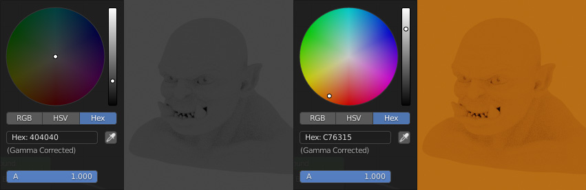
Figure 10.21 – The ambient light color changed from gray to orange
Note that the color of the background in the 3D Viewport changes. More importantly, colored light is being cast onto the sculpture from the environment. Evenly lit environments like this aren't very realistic or visually pleasing, so it's time to replace this singular ambient light color with an HDRI. We can do this by adding a node in the Shader editor.
- Open the Add menu in the top-left corner of the header of the Shader editor and choose Texture | Environment Texture. This will make a new Environment Texture node; this new node will immediately begin moving around with your mouse movements.
- Move the new node to the left of the Background node and left-click to place it:

Figure 10.22 – The Environment Texture node placed to the left of the Background node
This new node is a type of texture node. It requires an image texture to work correctly. In our case, we will be loading the HDRI into this node.
- Click the Open button on the Environment Texture node. This will open a file browser window.
- Navigate to the directory where you downloaded the phalzer_forest_01_4k.exr file. Select it and click the Open Image button to load it into Blender.
Now that the texture is loaded into the node, we need to hook up the Environment Texture node's Color output into the Background node's Color input.
- Click and drag from the yellow dot on the right side of the Environment Texture node to begin creating a noodle from the Color output.
- Drag the noodle to the yellow dot on the left side of the Background node to make a connection between the nodes:
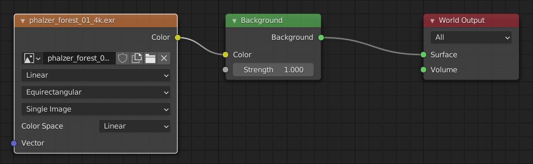
Figure 10.23 – The Environment Texture node hooked up to the Background node
Now that the connection has been made, the lighting information stored in the HDRI texture will be used to color the background and cast light onto the sculpture. Note that the color swatch on the Background node has been replaced by this connection because the swatch is no longer needed. Instead, the color value of each pixel in the HDRI is sampled by the Environment Texture node and passed into the Color slot of the Background node. This simple setup creates very pleasing results, as shown in the following screenshot:

Figure 10.24 – The orc sculpture lit with the HDRI
Note that this is not just a background image. The most important aspect of this environment texture is the realistic light that it casts into the scene. The results can be subtle, but there's no better way to make a render look realistic.
We can re-enable the Lights collection to bring back our area lights now.
The lights in this collection are looking a lot more subtle now because their brightness is very low relative to the brightness of the sun in the HDRI. Feel free to either increase the power of these lights or remove them altogether to suit the visual style you want for your render.
How it works…
HDRIs are very large texture files; each pixel contains values of color and light. Unlike regular images, there is a very high dynamic range that can be represented by each pixel. The vast difference in brightness between a light source and a regular surface can't be properly represented in a regular image. These brightness values are key to illuminating a 3D render.
There's more…
We can control the rotation of the HDRI if we add a Vector | Mapping node and an Input | Texture Coordinate node. Hook up the Vector output of the Mapping node into the Vector input of the Environment Texture node. Then, hook up the Generated output of the Texture Coordinate node into the Vector input of the Mapping node. This setup can be seen in the following screenshot:

Figure 10.25 – The Texture Coordinate and Mapping nodes added to control the rotation of the HDRI
The coordinates needed for sampling the texture are being generated by the Texture Coordinate node. Now, you can control the rotation of the HDRI by adjusting the Rotation Z value of the Mapping node.
If we don't want to use the HDRI for the background, but we still want to use it for casting light into the scene, we can add a few nodes to replace the background with a solid color. To achieve this, we need to add a Color | MixRGB node and an Input | Light Path node.
The Mix node will be used to blend between two colors. Hook up the Color output of the Environment Texture node into the Color1 slot and use the color swatch to choose a background color for the Color2 slot; we chose solid black (hex code 000000) for our example. Then, hook up the Color output of the Mix node into the Color input of the Background node. To mix the colors properly, hook up the Is Camera Ray output from the Light Path node into the Fac input on the Mix node. The final node setup can be seen in the following screenshot:

Figure 10.26 – The nodes required to use the HDRI for lighting and a solid color for the background
Nodes give us a lot of control over the way the environment is rendered. This finished node network is available in the hdriEnvironmentLighting_End.blend file, which can be downloaded here: https://github.com/PacktPublishing/Sculpting-the-Blender-Way/blob/main/Chapter10/hdriEnvironmentLighting_End.blend.
See also
Creating HDRIs requires specialized camera equipment and software. You don't need to make them yourself because there are many places to download high-quality HDRIs from the internet. The HDRI used in this example was provided by Poly Haven (formerly HDRI Haven), which is one of the most widely used collections of HDRIs available online. The HDRIs from this website are free to use: https://polyhaven.com/hdris.
Creating a clay material for the sculpture
Up to this point, our sculptures have been displayed with a default light gray material. But it doesn't have to be like this! We can create custom materials for our sculptures to make them look like they are made out of wood, metal, dirt, or any other substance we like.
Important Note
While sculpting, we used MatCaps to preview what our sculptures would look like with different colors. However, MatCaps are not the same as materials, and they can't be used for rendering.
Materials for rendering can be created using the Shader editor. Most modern render engines use Physically Based Rendering (PBR), also known as Physically Based Shading (PBS). This means that we can represent an almost limitless variety of materials with different colors, roughnesses, metallic properties, emissive properties, and much more by dialing in properties of the shader nodes using a standardized set of values. These values are based on the properties of materials in real life. All of the properties we need to represent most materials have been compiled together into one large node in the Shader editor known as the Principled BSDF.
For this section, we will stick to a very simple approach to creating materials. We'll hook up a set of image textures from a premade texture set. Texture sets are a collection of image texture files that contain information about material properties, including color, displacement, normal, and roughness. These image textures can be hooked up to their respective slots in the Principled BSDF node to create the material.
Getting ready
For this section, we can pick up where we left off in the Lighting up the environment with an HDRI section of this chapter. If you have not completed that section, you can begin this section with the hdriEnvironmentLighting_End.blend file, which can be downloaded here: https://github.com/PacktPublishing/Sculpting-the-Blender-Way/blob/main/Chapter10/hdriEnvironmentLighting_End.blend.
We will also need a set of textures to use for our material. We have provided a clay texture set for you to use. It consists of four image textures, which can be downloaded here: https://github.com/PacktPublishing/Sculpting-the-Blender-Way/tree/main/Chapter10/Clay004_2K-PNG.
Make sure you have the HDRI from the previous section downloaded as well; otherwise, the environment lighting will not render correctly.
Launch Blender and open the .blend file.
Creating a material from a texture set is fairly straightforward; we saw how to add an image into the Shader editor in the Lighting up the environment with an HDRI section of this chapter. The process for adding textures for materials is very similar, but we have to add one image texture node for each texture in the texture set, which is very tedious. Blender comes with an add-on that makes many node-related tasks easier; we just need to enable it in Blender's Preferences:
- In Blender's Topbar, open the Edit menu and choose Preferences. Once the Blender Preferences window appears, click on the Add-ons tab.
- Use the search bar in the top-right corner to search for Node Wrangler and check the box next to Node Wrangler to enable the add-on.
- Now that this add-on is enabled, several new hotkeys will be available to us in the Shader editor. Close the Blender Preferences window; the settings will be automatically saved.
How to do it…
Now, we can create a clay material for the sculpture:
- If the 3D Viewport isn't already set to the Rendered shading mode, switch to it now.
Our Shader editor is currently set to the World shader type. In order to create a material, we need to switch to the Object shader type.
- Change the shader type from Object to World using the drop-down menu in the top-left corner of the header of the Shader editor.
The World nodes will disappear, and now the Shader editor will display the nodes that belong to the material of the active object. However, no object is currently selected, so we won't see any nodes yet. Let's select the sculpture.
- Click to select the Orc object in the 3D Viewport.
Now that we have an active object, a button will appear in the header of the Shader editor:

Figure 10.27 – The New button in the header of the Shader editor
- Click the button labeled + New in the header of the Shader editor to create a new material for the active object.
The new material's name will be displayed where the + New button used to be. Its default name is Material, which is a terrible name.
- Click on the Material word to edit the name of the material and rename it Clay.
Now that we have a new material, two new nodes will appear inside of the Shader editor, a Principled BSDF node and a Material Output node, as you can see in the following screenshot:

Figure 10.28 – The Principled BSDF node and Material Output node
The Principled BSDF node is huge and contains many options, but don't let that intimidate you. We will leave most of the values at their defaults and only change the few that are needed to customize our clay material. Instead of hooking up our textures by hand, we can use one of the hotkeys that we enabled from the Node Wrangler add-on.
- Click on the Principled BSDF node to select it.
- Hover your mouse over the Shader editor and press the Add Principled texture setup hotkey, which is Ctrl + Shift + T. This will open a file browser window.
- Navigate to the directory where you downloaded the four images in the Clay004_2K-PNG texture set.
- Select all four textures: Clay004_2K_Color.png, Clay004_2K_Displacement.png, Clay004_2K_NormalGL.png, and Clay004_2K_Roughness.png.
- Click the Principled Texture Setup button to load all of the images into Blender.
It might take a moment to load. When it's finished, eight new nodes will be added to the Shader editor and automatically hooked up, as shown in the following screenshot:

Figure 10.29 – The new nodes added by the Principled Texture Setup button
Tip
If your computer is running slowly while editing the shader nodes, you can pause Cycles' viewport rendering by clicking the pause button in the top-right corner of the 3D Viewport header. Just remember to click the button again to resume rendering when you're ready.
Four of these new nodes are image texture nodes, one for each of the textures in the texture set. The Base Color node is set to use the sRGB Color Space since the image texture contains color data. The Roughness, Normal, and Displacement nodes are set to use the Non-Color Color Space since these image textures contain non-color data about their respective properties for the material.
All four of the image texture nodes are receiving their coordinates from the Mapping node, which is hooked up to the UV space output of the Texture Coordinate node. Textures can be sampled from several alternative texture coordinates by using the different outputs of this node.
The final two nodes are the Normal Map node and the Displacement node. Each of these nodes converts their input textures to be compatible with their respective properties.
We almost have everything we need with this setup. However, the textures are currently being sampled with the UV texture coordinate. UVs are special coordinates that we can make for our 3D models so that textures can be precisely mapped onto the surface of the models.
Making UVs is not easy with high-resolution sculptures, so let's use an alternative texture coordinate to automatically project the textures onto the sculpture without needing to make UVs:
- Click and drag from the top purple dot on the right side of the Texture Coordinate node to begin creating a noodle from the Generated output.
- Drag the noodle to the top purple dot on the left side of the Mapping node labeled Vector.
This will replace the previous connection with a new connection between the Generated output and the Vector input. Now, the textures will get their mapping coordinates from the generated coordinate space instead of the UV coordinate space.
One last bit of cleanup to make the Generated texture space behave better is to use Box projection instead of the current Flat projection and add a small amount of blending.
- Find the drop-down list on the Base Color node labeled Flat.
- Open the drop-down list and choose Box.
- A new field will appear below the drop-down list labeled Blend; set this to 0.200.
- Repeat these steps for the Roughness, Normal, and Displacement nodes.
Excellent – our finished node setup can be seen in the following screenshot:

Figure 10.30 – The finished node setup for the Clay material
Almost done; now we need to assign this finished Clay material to the other objects in the scene.
- Open the Select menu in the top-left corner of the header of the 3D Viewport and choose Select All by Type | Mesh.
- Open the Object menu in the top-left corner of the header of the 3D Viewport and choose Link/Transfer Data | Link Materials.
This will copy the material from the active object to all of the other mesh objects in the scene.
Now our sculpture has a clay material that makes it look much more detailed than it used to, as you can see in the following screenshot:
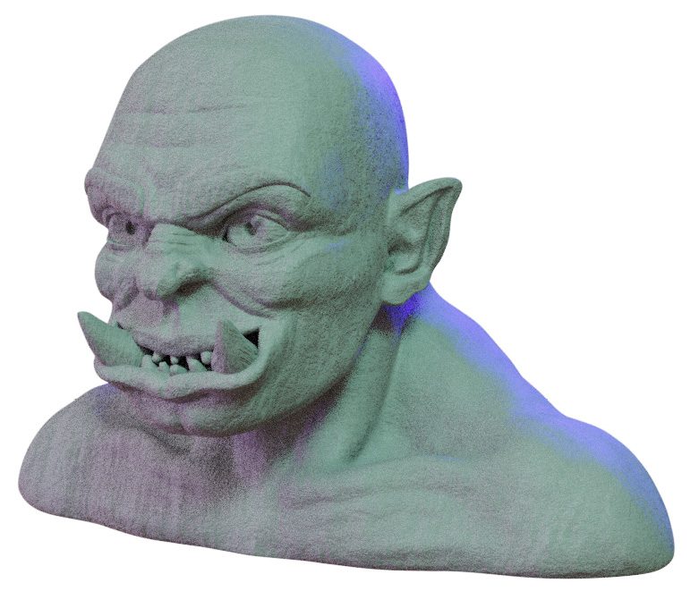
Figure 10.31 – The orc sculpture with the finished Clay material
There are many more ways to customize the materials of our sculptures. Different texture sets can be used to make the sculpture look like it's made from all sorts of materials. We chose this clay material for our example because traditional sculpting is done with clay, and it has a charming look while being easy to set up.
How it works…
PBR is the modern standard for making materials. The great thing about this is that there are numerous libraries of materials that will all be compatible with Blender and many other 3D software packages. The Principled BSDF node is a standard implementation of PBR properties into a single node.
The textures in a texture set are often referred to as maps. Each type of map delivers some type of data to the surface of the object. The Base Color map is the most straightforward type of texture; it supplies the color of the surface. The Roughness map determines how matte or shiny the surface will be; subtle variations throughout the roughness texture make the surface catch the light in a realistic way. The Normal map adds bumpy surface details that make objects look really detailed. The Displacement map raises and lowers the polygons of a mesh to add extra small details. This is very similar to a normal map but much more pronounced. Displacement textures aren't always necessary. At the time of this book's publication, displacement textures don't work in the Eevee render engine. Some texture sets include additional maps to control other properties of the material as well.
Texture sets can be created from source images taken from a camera, or they can be generated from scratch using procedural nodes. Once the texture set has been created, it can be easily hooked up in most 3D software to produce realistic results.
Mapping the texture set onto a model can be done with UVs or by using a box projection. The box projection method is useful because it works for all shapes with no additional setup required. The downside to a box projection is that it tends to produce ugly seams in some areas. These seams can be hidden with a small amount of blending to blur the edges of the projected textures.
There's more…
Materials such as these are easy to reuse across many sculptures and projects. The upcoming Blender 3.0 release will come with the brand-new Asset Browser that will make it easy to create a library of materials and apply them to objects in your scenes. You can read about the Asset Browser here: https://wiki.blender.org/wiki/Reference/Release_Notes/3.0/Asset_Browser.
See also
You can read more about the Principled BSDF node here: https://docs.blender.org/manual/en/latest/render/shader_nodes/shader/principled.html.
There are several free collections of texture sets available online. Here is a short list of excellent resources:
- Poly Haven: https://polyhaven.com/textures
- textures.com: https://www.textures.com/browse/pbr-materials/114558
- cgbookcase: https://www.cgbookcase.com/textures/
- 3DTextures.me: https://3dtextures.me/
- 3Dassets.one: https://www.3dassets.one/
- ambientCG: https://ambientcg.com/
The Clay004 texture set we used in this section was provided by ambientCG, licensed under CC0 1.0 Universal: https://ambientcg.com/view?id=Clay004.
Using a camera to render the sculpture
Modern 3D software allows us to use viewport rendering, which allows us to see nearly instantaneous results directly in our viewport while we work. However, viewport rendering is only intended for preview purposes. When we're happy with our preview render, we can move on to creating the final render. Blender needs to know which angle to create the final render from and which settings to use. Blender gets this information from the active camera.
A camera is a special type of object that contains several settings specific to rendering. Just like a camera in real life, we can position the camera, rotate it, frame our subject, adjust the focal length of the lens, and much more.
In this section, we will go through the basics of setting up a camera so that we can produce a final render of our sculpture.
Getting ready
For this section, we can pick up where we left off in the Creating a clay material for the sculpture section of this chapter. If you have not completed that section, you can begin this section with the clayMaterial_End.blend file, which can be downloaded here: https://github.com/PacktPublishing/Sculpting-the-Blender-Way/blob/main/Chapter10/clayMaterial_End.blend.
Make sure you have all of the textures from the previous section downloaded as well; otherwise, the clay material and environment lighting will not render correctly.
Launch Blender and open the .blend file. Once the file is loaded, we can set up our camera for rendering.
How to do it…
For this part of the process, we don't need to use the Rendered viewport shading mode; it will only slow us down while we set up the camera. You can stay in Rendered mode if you like, but for our example, we will switch to Solid mode.
First things first – we need to add a camera:
- Open the Add menu in the top-left corner of the header of the 3D Viewport and choose Camera.
- Positioning the camera can be achieved the same way as any other 3D object by using the Move and Rotate tools. However, it is easier to snap the camera to the angle of our viewport instead.
- Open the View menu in the top-left corner of the header of the 3D Viewport and choose Align View | Align Active Camera to View.
This will align the camera object to match the current viewing angle of the 3D Viewport, as shown in the following screenshot:
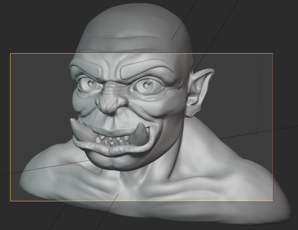
Figure 10.32 – The camera aligned with the 3D Viewport
Notice the yellow border inside of the viewport? This is the framing of the camera; the dark areas outside of this border will not appear in the final render.
We can keep the camera locked to the viewport with a setting in the Sidebar.
- Open the Sidebar by clicking the little < indicator along the right side of the main 3D Viewport or by pressing the N hotkey while your mouse is in the main 3D Viewport.
- Switch to the View tab of the Sidebar.
- Find the View Lock subsection of the Sidebar and expand it if it isn't already expanded.
- Check the box labeled Lock Camera to View.
Now, every time we pan, zoom, or orbit the 3D Viewport, the camera object will stay synchronized to the viewing angle of the 3D Viewport. Now, let's pick a camera angle that showcases our sculpture nicely.
Important Note
Choosing the camera angle is typically done before finalizing the placement of the lights. We already set up the lights earlier in this chapter, but feel free to adjust the positions of the lights as needed to match your preferred camera angle.
Rendering with a camera is very similar to taking a photograph with a camera in real life. Just like in photography, part of picking a good camera angle requires adjustments to the focal length of the camera lens.
- With the camera selected, navigate to the Object Data tab (represented by the green camera icon) in the Properties editor.
- Find the Focal Length setting under the Lens subsection.
The focal length of the camera determines how much perspective distortion the image will have. Low focal length values such as 12 mm will result in an exaggerated fisheye effect. Medium values like 50 mm are considered to be better for general purposes. Slightly higher values up to 115 mm are often used for character portraits. And huge values like 300 mm or higher are used for telephoto landscape photos. You can see the dramatic difference in perspective between 12 mm and 115 mm in the following screenshot:

Figure 10.33 – 12 mm versus 115 mm focal length
- Set the Focal Length setting to match the look you want for your render.
There is no correct setting here; it all depends on the look you want to showcase your sculpture in. The default setting is 50 mm because it is a fairly neutral setting. But we'll use 115 mm for our example since it is closer to what's typically used for characters.
Now that the Focal Length is set, move the camera into position to pick an angle you want to render the sculpture from.
Tip
Photographers often use composition guides such as the rule of thirds to help frame the subject in a pleasing way. We can turn on Composition Guides for the camera under the Viewport Display subsection of the Object Data tab in the Properties editor.
You can see the camera angle we've chosen for our example in the following screenshot:
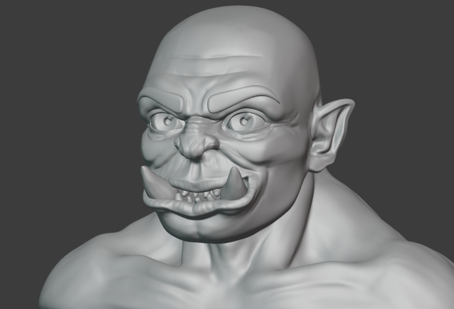
Figure 10.34 – The chosen camera angle to render the sculpture from
Once you're happy with the camera angle, it's a good idea to disable Lock Camera to View so that you don't accidentally move the camera again.
Now, we can render the image to see the results from the camera.
- Open the Render menu from Blender's Topbar and choose Render Image or press the F12 hotkey.
Regardless of the current viewport shading mode, this will render the final image using our chosen render engine – in our case, Cycles. By default, the render will appear in a new window. Our example render turned out like this:

Figure 10.35 – The rendered image of the sculpture
Important Note
Rendering in this way usually takes longer than viewport rendering since it is done with more samples and higher resolution. Expect it to take at least 5 minutes or considerably longer, depending on your computer's processing power.
Once the image finishes rendering, you can save it to your computer:
- Open the Image menu from the header of the Render window and choose Save As...; a file browser will appear.
- Use the file browser to choose a location, image format, and name for the rendered image, and then click the Save As Image button.
And there you have it – your first render is complete!
How it works…
Rendering the final image is slightly different from viewport rendering. Viewport rendering allows us to skip setting up a camera and several other settings, such as render resolution. This is great for preview purposes, but we should be sure to set up everything properly when it's time to do a final render.
We will take a look at how to give our render a final layer of polish using the other render settings in the Exporting the final render section of this chapter.
There's more…
Blender's cameras also support other tools from real-life photography, including depth of field. Depth of field allows us to focus on part of an object while the rest of the object becomes slightly blurry. This is often a desirable effect for artistic reasons. With the camera selected, the Object Data tab in the Properties editor will display a Depth of Field subsection. A Focus object can be chosen, and a low F-Stop value can be set to give the image some blurriness. Try focusing on the Eye_L object with an F-Stop value of 1.4, and then render the final image again.
The results will be subtle if the camera is far away from the subject, but a subtle blur effect like this can make the render feel more realistic, and the blurriness can help direct the audience's attention to the important parts of the sculpture.
Setting up a turntable for a 360-degree render
When we render our sculptures, we need to make a decision about how we want to present our artwork. Sometimes, our goal is to make an artistic composition with a nice camera angle, artistic use of lighting and shadow, and other features such as depth of field. This is what we focused on in the Using a camera to render the sculpture section of this chapter when we rendered the example orc sculpture.
However, artistic renders like this don't showcase the sculpture from every angle, and sometimes the lighting can make it difficult to see the details of the sculpture itself. When it comes to making portfolio pieces, it can be helpful to render your sculpture in a way that shows off your sculpting skills more than your lighting and rendering skills.
For this purpose, it is common to center the sculpture in the camera view, brightly light it, and animate it rotating 360 degrees so that it can be seen from every angle. This is called a turntable.
In this section, we will learn how to set up a turntable so that we can render a short animation of our sculpture rotating 360 degrees.
Getting ready
For this section, we can pick up where we left off in the Using a camera to render the sculpture section of this chapter. If you have not completed that section, you can begin this section with the cameraSetup_End.blend file, which can be downloaded here: https://github.com/PacktPublishing/Sculpting-the-Blender-Way/blob/main/Chapter10/cameraSetup_End.blend.
Make sure you have all of the textures from the previous section downloaded as well; otherwise, the clay material and environment lighting will not render correctly.
Launch Blender and open the .blend file. Once the file is loaded, we can set up our turntable.
How to do it…
Part of setting up a turntable requires the use of the Timeline editor for animation. Our current workspace doesn't include a Timeline editor, so we need to add a new workspace from Blender's Topbar:
- Find the workspaces listed at the top of Blender's user interface. In our example, there are only two workspaces available, Sculpting and Shading, but there is also a + button in the Topbar for adding other workspaces.
- Click the + button to add a workspace and choose General | Animation.
This will rearrange the user interface with a layout that is suited for animation. This workspace comprises editor types that we've seen in our other workspaces. This includes two 3D Viewports, the Outliner, Properties editor, and a Timeline, as you can see in the following screenshot:

Figure 10.36 – The Animation workspace
The 3D Viewport on the left is aligned to the camera, while the 3D Viewport on the right gives us a better view of the objects in the scene.
Now that we have a timeline editor available to us, we can set up the turntable. The easiest way to do this is to place an empty object in the center of the scene and animate it spinning 360 degrees.
- Open the Add menu in the top-left corner of the header of the 3D Viewport and choose Empty | Plane Axes.
- Rename the Empty object to Turntable.
Now, we need to place a keyframe on the Rotation Z transform field of the Turntable object:
- With the Turntable object selected, navigate to the Object tab (represented by the orange square icon) in the Properties editor.
- Click on the small dot to the right of the Rotation Z transform field to place a keyframe:

Figure 10.37 – The Rotation Z keyframe indicator
Clicking this dot will have several effects:
- The small dot will turn into a diamond shape, indicating that there is an animation keyframe on this field for the current frame of animation.
- The Rotation Z field will turn yellow, indicating that the field is controlled by animation data.
- Orange dots will appear in the Timeline editor underneath the blue current frame indicator to show where the keyframes are on the timeline – in this case, frame 1.
Let's have our turntable make a full revolution over the course of 5 seconds. By default, Blender plays animations at 24 frames per second, so this will require 120 frames of animation:
- Change the End setting in the bottom-right corner of the Timeline editor from 250 to 120.
Now, we need to place a second keyframe at the end of the animation. Animations that loop work best if we give them one additional frame, so our second keyframe should go on frame 121.
- Drag the blue current frame indicator to frame 121.
Changing the current frame will have several effects:
- The small diamond shape next to the Rotation Z field will become hollow, indicating that there is an animation keyframe on this field but not on the current frame of animation.
- The Rotation Z field will turn green, indicating that the field is controlled by animation data but there is no keyframe on the current frame.
Now, let's rotate the Turntable object one full rotation and add a keyframe to frame 121:
- Click to edit the Rotation Z field, type 360, and then press Enter.
The field will turn orange, indicating that the value of the field has been updated but a new keyframe has not yet been inserted.
- Click on the small hollow diamond to the right of the Rotation Z transform field to insert a second keyframe.
Clicking the hollow diamond will have several effects:
- The hollow diamond will become solid, once again indicating that there is an animation keyframe on this field for the current frame of animation.
- The Rotation Z field will turn yellow again, indicating that the field is controlled by animation data.
- More orange dots will appear in the Timeline editor underneath the blue current frame indicator to show where the keyframes are on the timeline – in this case, frame 121.
Excellent – we have our animation keyframes in place; the Turntable object will now rotate 360 degrees around its Z axis over the course of 120 frames. To see this in action, press the Play Animation button in the middle of the bottom of the Timeline or press the spacebar.
When you're finished viewing the animation, press the Esc key to cancel playing the animation and return to frame 121.
There's one remaining issue with our animation keyframes. They have ease-in and ease-out motion curves applied to them. This means that the turntable's rotation will speed up and slow down at the beginning and end of the animation instead of rotating at a constant rate. Let's fix this now:
- Open the Select menu in the top-left corner of the header of the Timeline and choose All.
- Open the Key menu in the top-left corner of the header of the Timeline and choose Handle Type | Vector.
The orange dots on the Timeline will change to squares to indicate the new handle type. Play the animation again and you'll see that the Turntable object rotates at a constant rate and the animation loops seamlessly.
Now, we need our camera and our lights to rotate around the sculpture. This can be done by nesting the camera and the lights inside of the turntable empty as child objects. Children follow the transforms of their parent automatically, so when the turntable rotates, the camera and the lights will too:
- Drag the blue current frame indicator to frame 1.
- Click to select the Camera object.
- Hold the Shift key down and click on the following objects to add them to the selection: Key Light, Fill Light, and Rim Light.
- Lastly, hold the Shift key and click to add the Turntable object to the selection.
- Open the Object menu in the top-left corner of the header of the 3D Viewport and choose Parent | Object.
This will make the Camera object and the three lights children of the Turntable object. Play the animation and you'll see the four objects spinning around the sculpture. We can also see what the animation looks like from the camera's perspective in the 3D Viewport on the left side of the UI.
The current position of the camera is a little awkward for the turntable, so let's center its position and aim it straight at the sculpture.
- Click to select the Camera object.
- With the Camera object selected, navigate to the Object tab (represented by the orange square icon) in the Properties editor.
- Let's adjust some of the transform values to center the sculpture in the camera's framing:
Change Location X to 0 m.
Change Location Y to -11 m.
Change Location Z to 0.825 m.
Change Rotation X to 90.
Change Rotation Y to 0.
Change Rotation Z to 0.
Now that the camera is positioned correctly, the turntable is ready. Play the animation to see how it looks. If you're happy with the animation, we can render it as a video. There are several options and considerations for rendering animations, so we will save that for the Exporting the final render section of this chapter.
How it works…
Turntables are a great way to showcase a sculpture from all angles. We typically want to aim our camera straight at the sculpture and use lighting that avoids dark shadows. Interesting camera angles and artistic shadows can look good for artistic renders, but they tend to hide the details of our sculpture that we're trying to showcase in a 360-degree render.
Choosing where to place our keyframes for looping animations can be a little confusing. For our turntable, we inserted two keyframes – one with 0 degrees of rotation and one with 360 degrees of rotation. 0 degrees and 360 degrees result in exactly the same angle. Because of this, including both of these frames would cause the animation to repeat an identical frame and stutter each time the animation loops. This is why we placed our 360-degree keyframe on 121, even though we end the animation playback at frame 120. Ending the animation one frame early ensures that the extra frame is not repeated, so we get a seamless loop.
Exporting the final render
There are several quality settings to consider when rendering and exporting our work; let's not trip at the finish line. Some of our render settings will be different, depending on the render engine we've chosen. We're going to stick with Cycles for this section. Let's discuss some of the settings we need for a high-quality render in Cycles.
We briefly mentioned the concept of samples and noise in the Setting up Rendered mode section of this chapter. Path tracing engines such as Cycles require multiple samples to create the final image. If we use a low number of samples, the image will render quickly, but the image will also have more undesirable noise. If we use a high number of samples, the image will take longer to render, but the noise will be significantly reduced.
There is no magic number for how many samples we need. Scenes with many lights and complex material properties require more samples than scenes with few lights and simple materials. Our orc example only requires a small number of samples to remove the noise, around 32–128. This is because the clay material is very simple to render. Our old monk example requires a slightly higher number of samples to remove the noise, around 256–512. This is because the old monk's skin and eyes materials have more complex properties such as subsurface scattering and refraction. If we use many lights and introduce other features such as a shallow depth of field and caustics, it will require considerably more samples to clean up all of the noise, sometimes as high as 1,024–4,096.
Reducing noise is important for a high-quality render, but there are a few other things we should set up as well, including resolution and file format.
In this section, we will make some small adjustments to Blender's output settings to make sure that our renders are exported with the highest quality. We'll also learn a little bit about the Blender community and where you can go to share your finished artwork.
Getting ready
For this section, we can use the artistic render that we set up in the Using a camera to render the sculpture section of this chapter, or we can use the 360 setup that we prepared in the Setting up a turntable for a 360-degree render section of this chapter.
If you have not completed either of these sections, you can download the cameraSetup_End.blend file from here: https://github.com/PacktPublishing/Sculpting-the-Blender-Way/blob/main/Chapter10/cameraSetup_End.blend, or you can download the turntableSetup_End.blend file here: https://github.com/PacktPublishing/Sculpting-the-Blender-Way/blob/main/Chapter10/turntableSetup_End.blend.
Make sure you have all of the textures from the previous sections downloaded as well; otherwise, the clay material and environment lighting will not render correctly.
Launch Blender and open the .blend file. Once the file is loaded, we can go over our export settings.
How to do it…
Some of the settings we need to adjust are split between the Render tab and the Output tab of the Properties editor. We'll start with the Render settings.
If you see noise in your render, try increasing the number of samples:
- Navigate to the Render tab (represented by the gray camera-back icon) in the Properties editor.
- Expand the Sampling subsection.
We can independently set the number of samples used in the 3D Viewport render and the number of samples used in the final render. Increase the number of samples in the Render and Viewport fields as needed to reduce noise in the final render and viewport renders respectively. We typically want to keep the Viewport samples low so that we have fast previews in the viewport while we set up our lights and other settings. We can use a higher number of samples for the render since it doesn't need to be fast.
Now, let's set up the resolution and file format for the export:
- Navigate to the Output tab (represented by the gray printer icon) in the Properties editor.
- Expand the Dimensions subsection.
From here, we can set the render resolution. The default 1920 x 1080 setting is the resolution for HD video. If you're exporting to social media such as Instagram, you can change this to a square ratio such as 1080 x 1080. Rendering with high samples takes a long time, so it is common to temporarily lower the resolution to do a pre-final render. We can do this by lowering the % slider to something small such as 25%. Don't forget to bring this back up to 100% when you're ready for the final render.
Finally, we should set our file output settings.
- Expand the Output subsection.
By default, the rendered images will be saved to the /tmp directory on your computer. You can change this using the folder icon to browse for a new output location.
If you're saving a single image, we recommend the following settings:
Set File Format to PNG.
Set Color to RGB.
Set Color Depth to 8.
- With the render settings set, open the Render menu from Blender's Topbar and choose Render Image or press the F12 hotkey.
If you're saving an animation (such as the turntable), you can use the same settings to render out an image sequence, or you can use the following settings to render a video file:
Set File Format to FFmpeg Video.
Set Color to RGB.
- Expand the Encoding subsection and set the following settings:
Set Container to Quicktime.
Set Video Codec to H.264.
Set Output Quality to High Quality.
Using the Eevee render engine to render the turntable animation will save a considerable amount of time since the animation has to render 120 individual frames.
- With the render settings set, open the Render menu from Blender's Topbar and choose Render Animation or press the Ctrl + F12 hotkey.
How it works…
There are many quality settings that can be set up differently between viewport renders and final renders. For example, the Render tab in the Properties editor has a subsection for adjusting the amount of sampling Cycles will use. You'll notice we can set different values for Viewport and Render. It is typical to use a low number of samples (around 32) in the Viewport so that the rendering happens as quickly as possible. A higher number of samples (around 128) is used for the final render because it will improve the quality of the final image and reduce noise, although it takes a lot longer to process the image. Sometimes, it is necessary to use extremely high values for the final render (around 4096). Having a separate setting for the viewport render samples is especially convenient in these extreme cases.
Some other settings are dependent on final renders as well. The Multiresolution modifier can be set to use a low subdivision level in the viewport but a high value in renders. Objects in the Outliner can be set to appear in the viewport but not in the final render, or vice versa.
Customizing these values will allow us to retain the flexibility of a fast viewport rendering while taking full control over the look of the final render.
There's more…
Increasing the number of samples is not the only way of reducing noise in Cycles renders. There are several denoising algorithms that we can use, including the OptiX AI denoiser and Open Image Denoise. Denoising can be enabled under the Sampling subsection of the Render tab of the Properties editor. Denoising can speed up render times. However, you should be aware that high-frequency details (such as skin pores) often get erased by denoising algorithms, as they can be mistaken for noise.
We can also adjust the Color Management settings at the bottom of the Render tab of the Properties editor. Try adjusting the Look option to give the render lower or higher contrast, depending on your artistic tastes.
See also
Incredible – you've made it to the end of the book! Now the only thing left is to share your sculptures with the online Blender community! Although we primarily used our orc sculpture for this chapter, you can go through this process with any of your sculptures that you've made throughout this book.
There are some great places to share your renders online. For professional portfolio work, https://www.artstation.com/ is an excellent place to post. There is an active Reddit page for Blender here: https://www.reddit.com/r/blender/. You can use the #b3d hashtag on Twitter and Instagram to let people know you made your art using Blender. You can also share your 3D models to https://sketchfab.com/ (however, you may need to reduce the polygon count of your sculptures before you can upload; try the Decimate modifier to quickly reduce the polycount).
There is an annual community sculpting event called Sculpt January. Throughout the month of January, there's a new prompt every day, providing you with a sculpting challenge. Check out the official Twitter account here: https://twitter.com/sculptjanuary.
Thank you so much for purchasing this book. I hope you've found it helpful. If you decide to share your work on social media, I would love to see your sculptures; tag me on Twitter @Xury46. It's been a pleasure helping you get started on your sculpting journey!