Chapter 5: Learning the Power of Subdivision and the Multiresolution Workflow
So far, in this book, we have learned how to create the larger forms of a model. However, we haven't had a chance to make any highly detailed sculptures yet. In this chapter, we'll learn about the appropriate workflow for creating highly detailed sculptures.
Before we can create detailed sculptures, we require a high-quality base mesh. We learned about all sorts of interesting techniques regarding how to create a base mesh in Chapter 4, How to Make a Base Mesh for a 3D Sculpture. Additionally, we learned how to use the Voxel Remesher to create a base mesh with our sculpting tools.
However, many of these base mesh creation techniques lack one major thing: a good topology for high-resolution sculpting. We will begin this chapter by learning about topology – in particular, what makes a topology good or bad for sculpting? Also, we'll learn how to use Blender's automatic QuadriFlow Remesher tool to generate a topology that can be used for the next part of the sculpting process.
Following this, we will learn about Subdivision Surfaces. Subdivision is a staple of 3D modeling software. It allows you to quickly create additional polygons for our models and, therefore, makes the model look smoother with a higher resolution.
Once we have a good understanding of how subdivision works, we can move on to the most important topic for highly detailed sculptures: Multiresolution. This is very closely related to subdivision, and it's a keystone element in any high-quality sculpture.
The main topics in this chapter are as follows:
- An overview of topology
- Generating an all-quad mesh with QuadriFlow
- Exploring subdivision surfaces
- Understanding when you're ready for multiresolution
- Using the Multiresolution modifier
- Recapturing details from the previous mesh
- Changing resolution for appropriate details
Technical requirements
For general requirements, please refer back to the Technical requirements section that was laid out in Chapter 1, Exploring Blender's User Interface for Sculpting.
You can download the files to follow along with this book at the GitHub link here: https://github.com/PacktPublishing/Sculpting-the-Blender-Way.
An overview of topology
In Chapter 2, Overview of Blender's Sculpting Workflows, we learned a little bit about topology. In the Creating dynamic topology with Dyntopo section of that chapter, we learned that Topology is a term we use to describe how all of the components (such as vertices, edges, and faces) of a mesh are interconnected. The topology of a model is not the same thing as the shape of the model. The positions of vertices, edges, and faces can move around and deform without changing the topology as long as none of the connecting edges are removed, rearranged, or added. For example, in the following diagram, we can observe two mesh objects with identical topology but different shapes:

Figure 5.1 – Two objects with the same topology but different shapes
In this example, the object on the left-hand side is made out of 16 quadrilaterals (quads). The topology of these quads forms a simple grid pattern. The object on the right-hand side has the same number of vertices (25), edges (40), and faces (16), and the connections between these components are identical. The only difference is that the components have been moved around so that the shape of the object is different.
The opposite is possible as well; we can have the same shape but a different topology, as illustrated in the following diagram:

Figure 5.2 – Two objects with the same shape but a different topology
In the preceding example, each of the objects forms a square with the same dimensions. We can describe them as having the same shape. However, the object on the right-hand side has a completely different arrangement of geometry, along with a different number of vertices (21), edges (37), and faces (17). This second object has a different topology than the first object.
In the Discovering the limitations of the basic sculpting mode section of Chapter 2, Overview of Blender's Sculpting Workflows, we learned that there is a close relationship between the topology of an object and the shape of an object. The shape can be deformed, but only within a small limit. If you push the shape past this limit, the polygons will become stretched out and the topology will no longer support the shape properly. This can lead to bad (or even completely unusable) results in our sculptures.
We briefly looked at how to combat this limitation by using the dynamic topology feature. It produces a topology that looks something like this:

Figure 5.3 – The topology generated by the dynamic topology (Dyntopo) feature
This topology is certainly better than a bunch of stretched-out polygons, as the shapes of the sculpture are being supported by lots of little triangles. However, this type of topology has many issues. For instance, there are no clear patterns to follow, and many areas are jagged and can't be easily smoothed. This surface is prone to shading errors, and it will be nearly impossible to get crisp lines around the eyelids, upper lip, or anywhere else that requires better topology.
Because of these issues, we've avoided using the Dyntopo feature throughout this book. Instead, we've been using the Voxel Remesher to alter the topology of our sculptures and quickly generate new polygons to support the shapes we want to sculpt. The topology from this workflow appears similar to the following:
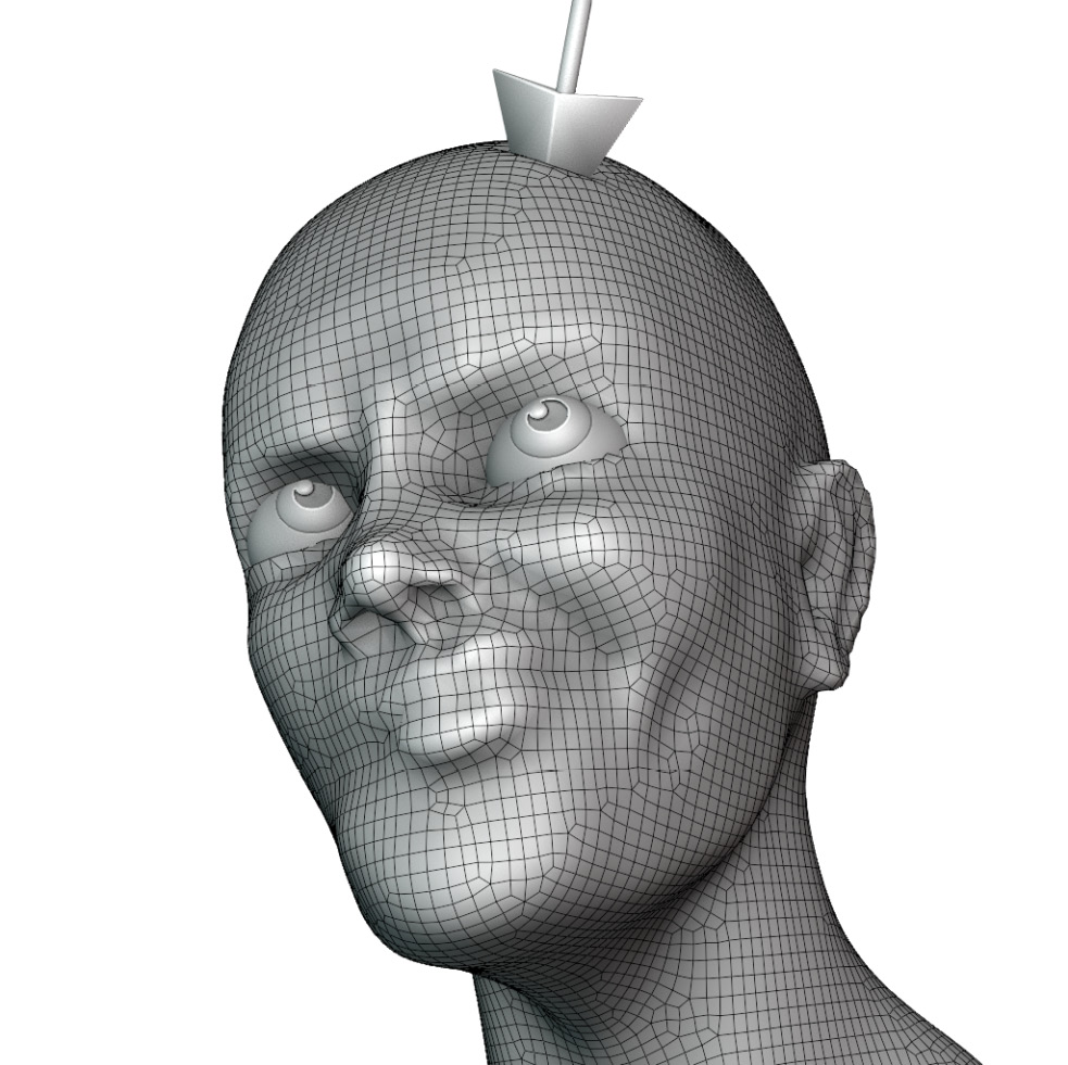
Figure 5.4 – The topology generated by the Voxel Remesher
This cleans up many of the issues that we had with our previous example, but it still has problems. The Voxel Remesher works based on a 3D grid – the generated topology always follows the grid. This is excellent for getting quick results, but it doesn't make the best topology for highly detailed sculptures.
In the Creating a base mesh with box modeling section of Chapter 4, How to Make a Base Mesh for a 3D Sculpture, we briefly touched on the idea of Edge Loops. Edge Loops are a crucial part of topology. Edge Loops are naturally formed in between the quads in a grid pattern. In a good topology, the edges are guided through the surface of the model giving it good edge flow. In the preceding example, we have a grid pattern, but we do not have a good edge flow. The edges follow the voxel grid pattern instead of flowing through the facial features of the character.
When we're ready to add details to a model, we need to rearrange the topology so that it follows the contours and details of the sculpture instead of blindly following the voxel grid patterns. A better result for high detail sculpting should look similar to the following example:

Figure 5.5 – The topology that is ready for the detail stage of the sculpting process
In the preceding example, notice how the polygons follow the contours of the lips, jaw, eyelids, brow, and other features. While this example might not be perfect (there's no such thing as perfect), it is much cleaner than either of the previous examples, and it will work well for us when we get into sculpting the highly detailed parts because the topology is reinforcing the contours and shapes of the model.
One downside to this type of topology is that it requires us to nail down the shape of the sculpture first. If we wanted to add new larger features to this character, such as a pair of horns, this topology wouldn't allow for those additions. That's why we use the Voxel Remesher and our other base mesh creation methods for the early stages of the sculpting process. When we're ready to sculpt the high-resolution details, we need to upgrade the model to this better type of topology and stop using the Voxel Remesher.
For the best results, we need to learn about the topology arrangements that will create the most efficient sculptures and how we can achieve these results. There is a lot to learn about topology. However, we're just going to focus on several of the simple ideas because this is a book about sculpting, and we want to get you back to sculpting instead of spending too much time reading about technical subjects.
In this section, we'll explore the topology of a character model and highlight some of the key features that we need to look for in a good topology.
Getting ready
Download the example highResCharacterTopology.blend character file from https://github.com/PacktPublishing/Sculpting-the-Blender-Way/blob/main/Chapter05/highResCharacterTopology.blend.
Launch Blender and open the highResCharacterTopology.blend file. Once you've opened the file, we're ready to explore the topology of this sculpture.
How to do it…
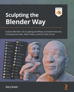
The character in this .blend file is named Lilly. Lilly is made up of many individual pieces. Each of these pieces have been given an appropriate topology to represent their shapes. Turn on the Wireframe display in the Viewport Overlays pop-over menu so that we can view her topology. With this display turned on, grid patterns will be laid on top of the character, as shown in the following screenshot:

Figure 5.6 – The high-resolution character Lilly with the wireframe overlay turned on
Take a look at the polygons on Lilly's sweatshirt – they work together to form a very clean grid pattern that follows the sleeves, torso, hood, pull strings, and other areas appropriately. Instead of thinking about the Edge Loops of this mesh, it can be helpful to look at the Face Loops. Face Loops are almost the same thing as Edge Loops, but they are made of faces instead of edges – who would have guessed?
Face Loops are always formed when quads are adjacent to each other. Triangles and n-gons do not contribute to Face Loops. If we place enough quads together, we will end up with very clean grid patterns that are made up of Face Loops. To visualize the Face Loops, let's hop into Edit Mode to explore Lilly's sweatshirt:
- Select Lilly's sweatshirt.
- Press the Tab key to enter Edit Mode.
- Hover your mouse over one of the quads around the midsection of the sweatshirt.
- Hold down the Alt key and click to select a face loop:

Figure 5.7 – A face loop around the midsection of the sweatshirt, highlighted in orange
All 3D software comes with shortcuts with which we select entire Face Loops like this. These loops are crucial for creating high-quality models. For now, we're just exploring the existing topology in this model. Notice how the face loop flows all the way around the character's midsection to form a complete loop. There are many loops exactly like this one that work together to form the entirety of the midsection. Try holding the Alt key and clicking on more faces of the model. Notice how the quads wrap around the sleeves, the hood, and the other areas to support the shape of the sweatshirt. This is a good topology.
Up next, let's explore the character's face:
- Press the Tab key to exit Edit Mode.
- Select Lilly's head.
- Press the Tab key again to enter Edit Mode for the head mesh.
- Zoom in on Lilly's head.
- Hold down the Alt key and click to select a face loop near her mouth:

Figure 5.8 – A face loop around Lilly's mouth, highlighted in orange
Notice how the quads form a circle around Lilly's mouth area. There are several Face Loops just like this one surrounding her mouth. These concentric circles will help to reinforce the details of her lips during the high-resolution sculpting process. We can view a similar arrangement around Lilly's eyes:
- Hold down the Alt key and click to select a face loop near her eye:

Figure 5.9 – A face loop around Lilly's eye, highlighted in orange
Once again, pay attention to how the quads form a circle around the eye. This will help us a lot when we go to sharpen the eyelids. There are other helpful loops in this character's topology as well; for instance, the jaw.
- Orbit the 3D Viewport so that we can observe Lilly's jawline.
- Hold down the Alt key and click to select the face loop that follows the jawline:

Figure 5.10 – A face loop following the contour of Lilly's jawline, highlighted in orange
This is another very common face loop to observe in good topology for a character's head. At least one face loop following the jawline will give us the structure that we need to make a pronounced jawline in the high-resolution sculpture.
Please feel free to keep exploring the topology of this character before moving on.
How it works…
Good topology is not just about grid patterns; it's about good edge flow that supports the shapes of our sculptures. The best way to visualize this edge flow is by highlighting Face Loops and Edge Loops in the topology of the model.
There's no such thing as a perfect topology. The topology just has to be arranged well enough to support the shapes we are trying to sculpt. Generally, it is a good thing to have the mesh be made entirely out of quads instead of using triangles and n-gons because only quads create Face Loops.
The Voxel Remesher does not create good Face Loops. So, next, we will learn about a better way to generate a topology that can be used for the high detail stage of the sculpting process.
Generating an all-quad mesh with QuadriFlow
So far, we've been using the Voxel Remesher to generate new polygons for our sculptures. We learned about this type of remeshing in the Practicing the basics of the Voxel Remesher section of Chapter 2, Overview of Blender's Sculpting Workflows. The advantage of the Voxel Remesher algorithm is that it generates new geometry almost instantaneously, so we can use it while we sculpt. However, the arrangement of the polygons is not ideal for a finished base mesh.
As we learned in the An overview of topology section of this chapter, the polygons of a base mesh should flow through the details of the model, supporting things such as the mouth, eye sockets, bridge of the nose, and more.
In this section, we will try using the QuadriFlow remesher to convert a model into a base mesh with good edge flow that can be used in high-resolution sculpting.
Getting ready
In this section, we need to start with a sculpture that we can remesh. You can follow the instructions in this section using a sculpture of your own. If you would rather start this section using our example, download and open the voxelCharacterHead.blend file at https://github.com/PacktPublishing/Sculpting-the-Blender-Way/blob/main/Chapter05/voxelCharacterHead.blend.
Launch Blender, and open the .blend file for your sculpture. The provided example has already been set up correctly; however, if you're using your own sculpture, switch to Object Mode. Open the Viewport Overlays pop-over menu and turn on Wireframe. Then, set the wireframe value to 1.000 so that we can view all the edges of the sculpture.
Once this has all been set up, we'll be ready to use QuadriFlow to remesh the sculpture.
How to do it…
Because we are in Object Mode, we have a variety of options available for making adjustments to the whole object, including the QuadriFlow remesh settings. With the sculpture selected, several colored tabs will appear in the Properties editor:
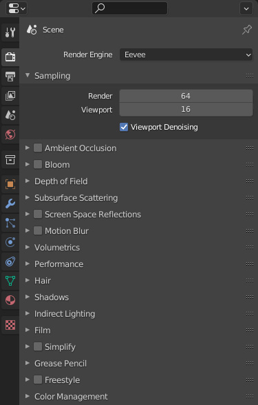
Figure 5.11 – The Properties editor with colored icons along the left-hand side
Each of these colored tabs contains settings and information about our model. To remesh this model with the QuadriFlow remesher, we need to turn our attention to the green triangle-shaped Object Data Properties tab:
- Click on the green object data tab to view the settings related to the geometry of the model.
- Scroll down to find the Remesh subsection of the Object Data Properties tab.
- Click on the drop-down arrow to the left-hand side of Remesh to expand this subsection:
Figure 5.12 – The Remesh settings in the Properties editor
Note that the current Mode setting is set to Voxel – this should look familiar. These are the same settings that we've used to voxel remesh our sculpture. So far, in this book, we've accessed these settings via the 3D Viewport header while in Sculpt Mode. Now that we've switched to Object Mode, we can access some additional settings right here in the Properties editor.
To generate a base mesh with a good edge flow, we need to change the remeshing from Mode to Quad.
Important Note
The QuadriFlow remesher is a relatively recent addition to Blender. As of writing, the user interface for this feature is awkward to use, but it might be improved for future releases of Blender.
Once we've switched to Quad mode, we can access the QuadriFlow remesh settings by clicking on the QuadriFlow Remesh button. The settings pop-up menu will appear, which you can view in the following screenshot:
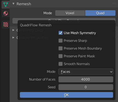
Figure 5.13 – The QuadriFlow remesh options as displayed in the Properties editor
We can adjust the target number of polygons we would like the QuadriFlow algorithm to generate. Let's try 9,000:
- Change the Number of Faces setting from 4000 to 9000.
- Click on the OK button.
This could take a few seconds to process. You can observe the progress in the status bar at the very bottom of Blender's user interface. When the QuadriFlow remesher is finished, your sculpture will be updated to have a clean arrangement of quadrilateral polygons:

Figure 5.14 – The remeshed character before and after using the QuadriFlow remesher
Sometimes, the Use Mesh Symmetry option in the QuadriFlow remesh settings can leave behind holes along the symmetry line of the remeshed object. If this happens to your sculpture, you can try fixing it by performing these steps:
- Click on the Modifiers tab in the Properties editor (it's the blue wrench-shaped tab).
- Click on Add Modifier, and choose Mirror underneath the Generate column.
- Click on the X toggle next to Bisect so that we don't introduce any unwanted geometry across the symmetry line.
- Set the Merge value high enough to seal all of the holes along the symmetry line. In our example, 0.03 m works well.
- Click on the drop-down arrow in the upper-right corner of the Mirror modifier and choose Apply.
Our example character turned out as follows:

Figure 5.15 – The final topology after using the QuadriFlow remesher and fixing the holes
You might be thinking that this result looks worse than the previous version of the sculpture. However, that is to be expected for a finished base mesh. This is actually a good start. It's not supposed to have all of the details – it just needs to have a topology that supports the major shapes. By the end of this chapter, we'll have understood how to use a base mesh such as this in the multiresolution workflow to create the high-resolution details that we have been unable to create with previous methods.
How it works…
The Quad remesher uses the QuadriFlow algorithm to analyze the model and identify contours and major shapes. This type of remeshing will take a lot longer than voxel remeshing. However, when it's finished, the topology should follow the contours of the sculpture.
We can use QuadriFlow to convert almost any model into a base mesh that is ready for the next stages of the sculpting workflow. Many of the base meshes that we learned to create in Chapter 4, How to Make a Base Mesh for a 3D Sculpture, will need to be remeshed in this way. The QuadriFlow remesher works best if the input geometry has been completely merged before running the remeshing algorithm. If your input geometry is made from non-contiguous parts, you might need to run the Voxel Remesher once with a small voxel size in order to merge all of the pieces together before using QuadriFlow to generate a good edge flow for the base mesh.
There's more…
Some of the details of the original sculpture might have been lost during this remeshing process. If we keep a copy of the original sculpture around, we can reproject the details from the old sculpture onto the newly remeshed sculpture so that we get the details back. We will learn how to do this in the Recapturing details from the previous mesh section of this chapter.
See also
Blender's built-in option for quad remeshing uses the QuadriFlow algorithm. You can read more about the differences between the QuadriFlow remesher and the Voxel Remesher at https://docs.blender.org/manual/en/latest/modeling/meshes/retopology.html.
QuadriFlow is not the only option available for automatic quad remeshing. There are several premium options that are available as add-ons. An excellent place to shop for resources is the Blender Market: https://blendermarket.com. Here, there are several remeshing tools available for various use cases. The Blender Market is organized by the Blender community, so new tools are available all the time.
One of the highest quality automatic remeshing tools is the Exoside Quad Remesher, which is available at https://exoside.com/quadremesher/. This tool is not a particularly affordable option for hobbyists. However, if you require the best results possible from a one-click solution, the results of this tool are excellent.
Exploring subdivision surfaces
The Catmull–Clark Subdivision Surface algorithm was invented by some of the very talented engineers at Pixar. It has been a very important innovation in the 3D industry, as it provides you with a way in which to make models look smoother. This is achieved by taking input geometry and dividing all of the polygons into smaller polygons. Then, the spacing between the vertices of these new polygons is averaged to create a smooth result.
This algorithm works especially well with quadrilaterals. Each quad can be divided vertically and horizontally at the same time, which turns a single quad into a small grid of four quads. This algorithm can be repeated for multiple levels of subdivision. A second iteration on a quad will result in 16 small quads in a very clean grid pattern, as you can view in the following diagram:
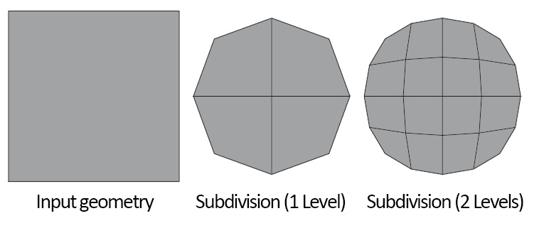
Figure 5.16 – A quad with various levels of subdivision
Generally, two levels of the subdivision are enough for good results. This can be somewhat expensive for our computers to calculate because of the exponential nature of this algorithm. When working with subdivision surfaces, we tend to work with input geometry that has relatively few polygons and good edge flow.
In this section, we will take a look at what subdivision can do for our models. Later in this chapter, we will learn how subdivision is relevant to the sculpting workflow.
Getting ready
Download the example subdivisionExamples.blend file from https://github.com/PacktPublishing/Sculpting-the-Blender-Way/blob/main/Chapter05/subdivisionExamples.blend.
Launch Blender, and open the subdivisionExamples.blend file. Once you've opened the file, we're ready to try subdividing some models.
How to do it…
The example file has six example models, as you can see in the following diagram:
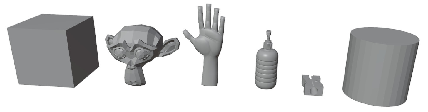
Figure 5.17 – Six example objects, from left to right: Cube, Suzanne, Hand, Bottle, Sharpener, and Cylinder
Some of these objects will work better with subdivision than others. Let's work our way from left to right and add subdivisions. We'll start with the cube:
- Click on the Cube object to select it.
- Open the View menu in the upper-left corner of the 3D Viewport and choose Frame Selected. This will zoom in and center the cube so that we can see what we will be doing in the next steps.
Tip
It is useful to use the Frame Selected option each time we work on a different object or when we work on a different piece of the same object. If you have a numpad on your keyboard, you can use the period hotkey (.) on the numpad to frame the selection. Alternatively, you can press the tilde key (~) to open the View pie menu and choose View Selected in the lower-right corner of the pie menu.
- If the viewport ends up zoomed in too far, use the scroll wheel to zoom out until you can view the whole cube.
Now we're ready to add subdivision to the model. In Blender, subdivision is available as a modifier. We learned a little bit about modifiers in Chapter 4, How to Make a Base Mesh for a 3D Sculpture. We will use the Properties editor to add a Subdivision Surface modifier to the cube.
- Click on the blue wrench tab in the Properties editor to switch to the Modifiers tab.
- Click on Add Modifier and choose Subdivision Surface from the Generate column in the list of modifiers.
- Increase the Levels Viewport value from 1 to 2.
Excellent! The cube has gone from 6 quads to 24 quads, to 96 quads. The extra vertices of the cube have their positions averaged to create a smooth surface, as you can see in the following diagram:

Figure 5.18 – A cube with no subdivision, one level of subdivision, and two levels of subdivision
Important Note
The Subdivision Surface modifier adds polygons to the model at an exponential rate. Two levels of subdivision are enough for most models – anything higher will usually take a long time to process. You will most likely never need to go higher than six, as subdivision levels past this point will almost always cause your computer to run out of memory and crash Blender.
The cube looks a lot smoother now because of the subdivision algorithm. The rigid corners have smoothed out and the end result is a Quad Sphere. The way in which these objects become smoother is completely dependent on the topology of the input geometry. Models with good edge flow will be better at retaining their original shapes when subdivision is applied. Let's repeat this process for each object in the scene and watch what happens to their shapes.
Tip
There is a hotkey for quickly applying a Subdivision Surface modifier to the selected object. While in Object Mode, press Ctrl + 2 to add a Subdivision Surface modifier with two levels of subdivision.
When subdivision is applied to Suzanne (the monkey), she goes from being very blocky to looking very smooth. Her original shape has been a lot better retained than the shape of the cube. We can view a before and after comparison in the following diagram:
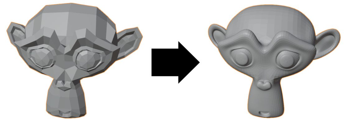
Figure 5.19 – Suzanne with no subdivision (on the left-hand side) and two levels of subdivision (on the right-hand side)
This is an excellent use case for subdivision; look at her ears, brow, and nose. Each of these shapes has had its structure defined by the topology of the input geometry – we can clearly see the polygons supporting these areas. Subdivision has emphasized each of these features by adding polygons and smoothing.
However, Suzanne is still looking a little bit faceted. A bit like a diamond, each face is catching the light, and she doesn't look very smooth yet. Instead of adding more levels of subdivision, we can request the edges of the model to blur together by applying a different type of shading to this geometry. Right now, Suzanne is using Flat Shading. Let's change this to Smooth Shading:
- Make sure Suzanne is still selected.
- Open the Object menu in the upper-left corner of the 3D Viewport and choose Shade Smooth:

Figure 5.20 – Suzanne with flat shading (on the left-hand side) and smooth shading (on the right-hand side)
There, she's looking very smooth now. Smooth shading makes the edges between the polygons appear smoother without adding any additional geometry. This feature is not part of the subdivision surfaces algorithm, but it does work very well when used alongside subdivision.
Now, let's take a look at the hand model. Select the hand, frame it in the viewport so that we can get a good look at it, then give it two levels of subdivision. The result can be viewed in the following diagram:

Figure 5.21 – The hand model with no subdivision and two levels of subdivision
The blocky fingertips have been completely rounded out by subdivision. Additionally, all other areas of the hand have been given extra smoothness. We can visualize this better by turning on the wireframe overlay:
- Open the Viewport Overlays pop-over menu and activate the Wireframe overlay.
- Observe the settings for the Subdivision Surface modifier in the Properties editor, and toggle off the Optimal Display setting:

Figure 5.22 – The wireframe of the subdivided hand with and without the Optimal Display setting enabled
Notice that the original topology of the hand model has a direct influence over the resulting topology of the subdivided hand. All of the original Edge Loops and Face Loops are still there; subdivision simply added divisions between these loops. It is important for our models to have good topology when we use the subdivision algorithm.
Turn off the wireframe overlay before moving on. Following this, we can look at the other examples. Select the bottle, frame it in the viewport so that we can get a good look at its spout, then give it two levels of subdivision. The result can be viewed in the following diagram:

Figure 5.23 – The bottle model with no subdivision and two levels of subdivision
Here, the effect is subtle. The original model already looked pretty smooth, in part because it had smooth shading applied to it. However, in this scenario, adding subdivision is still helpful for the extremely high-level detail. This model goes from looking good to very refined and polished. We can no longer make out any jagged edges along the spout; even the smooth shaded edges look crisper.
We need to understand that subdivision is only as good as the input geometry. If the geometry doesn't have a topology that works well with subdivision, then we're going to get bad results. Let's see what happens to the sharpener model when we try to add subdivision. Select the sharpener, frame it in the viewport, then give it two levels of subdivision. The result can be viewed in the following diagram:
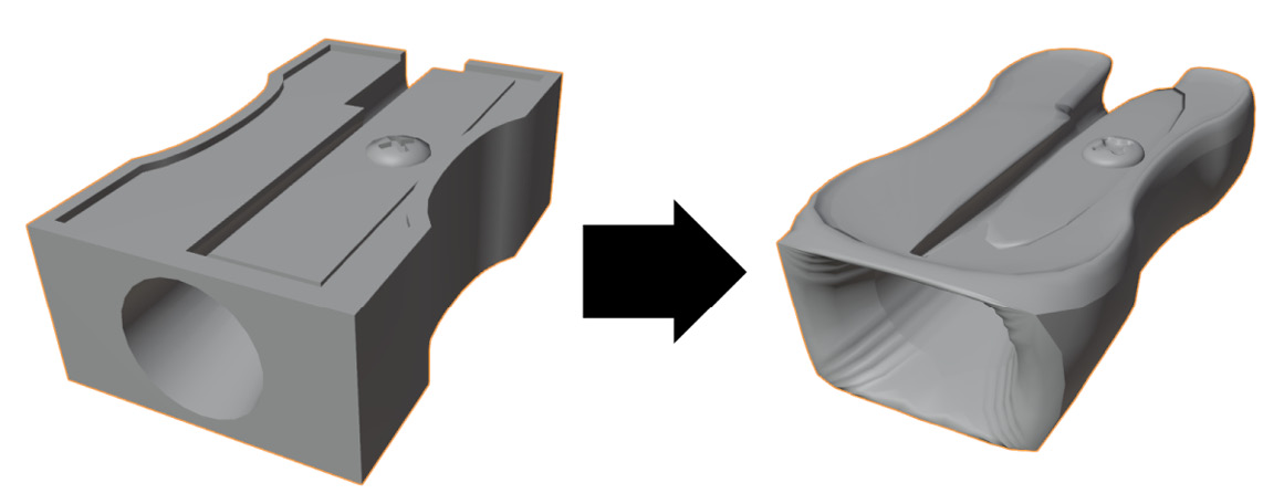
Figure 5.24 – The pencil sharpener model with no subdivision and two levels of subdivision
Oh, no! This model did not hold up well under subdivision. This is because the topology of this model was not created with subdivision in mind. Let's take a look at the problems within this model:
- Turn on the wireframe overlay again so that we can view the topology of the sharpener.
- Remove the Subdivision Surface modifier by clicking on the X toggle in the upper-right corner of the modifier settings in the Properties editor.
Good, now we can view the topology of the sharpener:

Figure 5.25 – The pencil sharpener's topology
It has lots of triangles and a lack of grid patterns across its surface. The left-hand side of the top area is made out of many triangles that have no discernible pattern. Similarly, the front area surrounding the circular hole is made up of many triangles, so there is no grid pattern here either. Subdivision does not work well with this type of topology. This type of model might be useful for other applications such as video games where subdivision isn't necessary. However, for our purposes, we won't be able to use a topology such as this.
Lastly, let's take a look at another problematic example: the cylinder. Select the cylinder object, frame it in the viewport, then give it two levels of subdivision. The result can be seen in the following diagram:
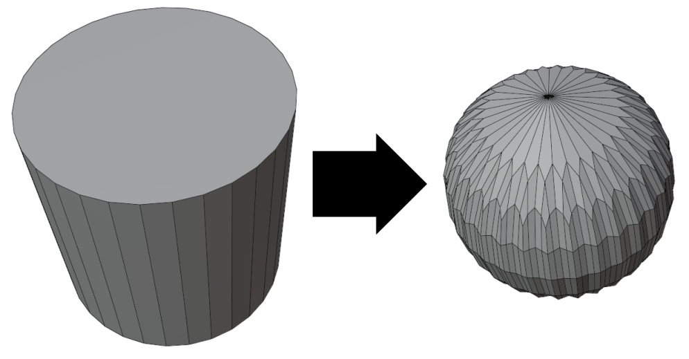
Figure 5.26 – The cylinder with no subdivision and two levels of subdivision
In the preceding example, the top of the cylinder is made from an n-gon. This n-gon becomes subdivided into one of the most infamously problematic types of topology: a high valence pole. There are so many edges connected to this single vertex that we end up with a strange star-shaped pattern with a wavy surface. No amount of smoothing will reduce this problem. Bad topology has ruined this model.
There's a lot more to learn about topology and how it interacts with subdivision. However, this is a book about sculpting, not topology, so it's time for us to move on.
How it works…
The subdivision algorithm is particularly good at making objects look smooth. The underlying structure of the model's topology is still there; it's just been divided and made smoother.
You might already have some guesses as to how subdivision can be useful for us in our sculpting workflow. We understand that in order to sculpt highly detailed models, we require lots of polygons. However, for the surfaces of our models to look really clean and of high quality, we need to have good topology.
Subdivision is the first part of the solution for making high-quality sculptures; the second part is multiresolution, which we will learn about shortly.
See also
There are some excellent examples of topology that are well suited for subdivision. They are available at https://graphics.pixar.com/opensubdiv/docs/mod_notes.html.
Understanding when you're ready for multiresolution
We took a brief look at the multiresolution workflow in the Exploring the most powerful sculpting mode – multiresolution section of Chapter 2, Overview of Blender's Sculpting Workflows. We learned that multiresolution is the best way to create highly detailed sculptures. Of course, there is a problem with multiresolution; it requires us to commit to a particular shape and create a topology that supports this shape.
The earliest stages of the sculpting workflow are all about deciding what that shape is going to be. However, it can be difficult to know when you've gone far enough and whether you're ready to start the multiresolution stage. If you switch to multiresolution too early, you might end up being unable to add large additional details to the model. However, if you switch to multiresolution too late, then some of the details that you've already sculpted could be lost in the transition.
In this section, we'll take a look at some examples that will give you a good idea regarding when you're ready to make the switch to multiresolution.
Getting ready
Download the example voxelVSQuad.blend character file at https://github.com/PacktPublishing/Sculpting-the-Blender-Way/blob/main/Chapter05/voxelVSQuad.blend.
Launch Blender and open the voxelVSQuad.blend file. Once you've opened the file, we'll be ready to start.
How to do it…
In this file, you'll find three vampire character heads. Let's take a look at the one on the left-hand side:
- Click on the head_voxelRemeshed object on the left-hand side to select it.
- Open the View menu in the upper-left corner of the 3D Viewport and choose Frame Selected.
Take a look at the model for a moment. Once you're used to the way it looks, take a look at it again with the wireframe turned on.
- Open the Viewport Overlays pop-over menu and activate the Wireframe overlay.
Excluding the teeth and the eyes, this vampire character has been created using the Voxel Remesher. This should be obvious to you by now given the grid pattern that can be observed in the following diagram:
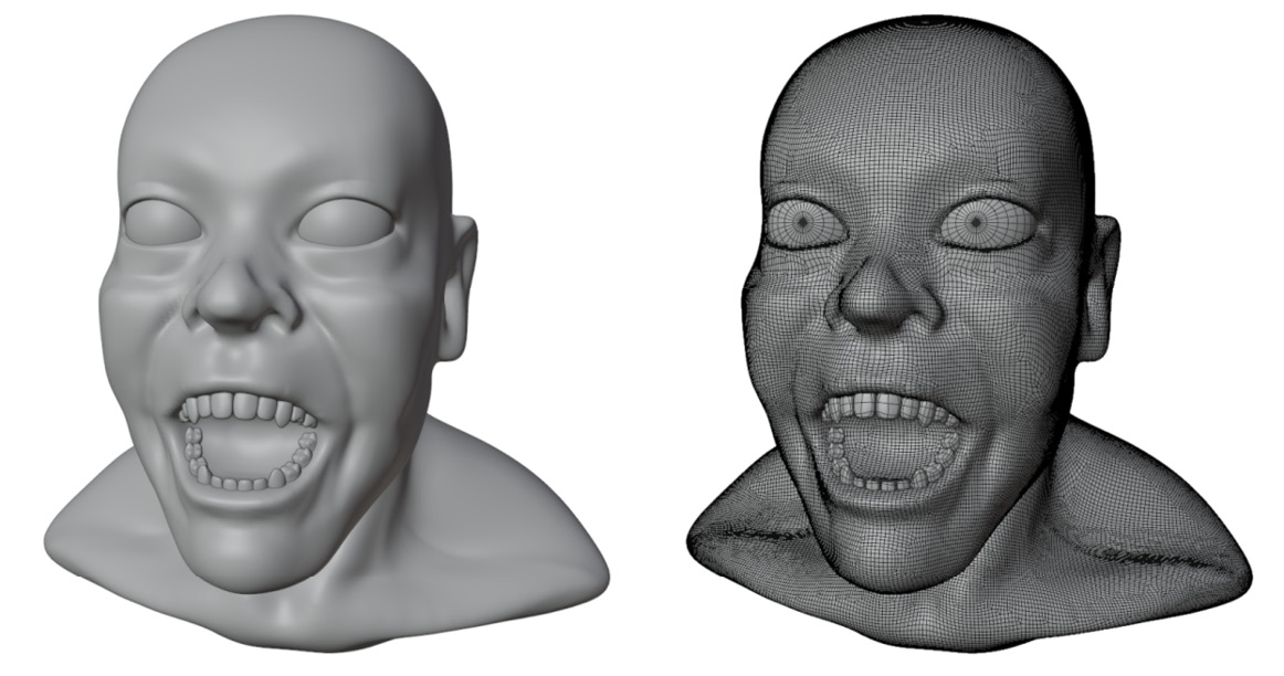
Figure 5.27 – The vampire character with the Voxel Remesher topology
This character has just the right level of detail for us to begin the multiresolution phase. But how do we know that? We're starting to bump up against the limits of what the Voxel Remesher can do. The polygon density is very high on this model and it's starting to create issues. The eyelids have been sharpened with the Pinch brush, which creates a very crisp edge. However, because of the way the Voxel Remesher works, these crisp edges will be erased if we run the Voxel Remesher again. Crisp details won't be properly preserved in the sculpting process unless we begin using multiresolution.
Additionally, there are other problems present in this model. In some areas, the topology is creating a very lumpy surface. Observe the perimeter of the upper lip; additionally, take a look at the ridge between the nostril and the corner of the mouth. These diagonal areas are fighting against the current topology, so it is not possible to create a smooth surface here until we begin multiresolution.
Some details are always lost when we convert from our old topology into our multiresolution-ready topology. For this reason, we want to avoid putting in too much detail prior to multiresolution. Don't bother trying to sculpt wrinkles, skin pores, small scars, or other little details yet. Even the sharpened eyelids are a little bit too detailed at this stage.
Before we move on to the multiresolution phase, we need to determine whether all of the major forms are in place. Do we need to add anything while we're still in the Voxel Remesher stage: horns? Elf ears? A third eye? A body? These things must all be added before entering multiresolution.
This vampire character isn't going to have a complete body, and all of the shapes we want to capture are here. All of the other details, such as the teeth and eyeballs, can be done as separate objects. So, everything is properly in place, and we can generate a better topology for the model. We already learned how to do this in the Generating an all-quad mesh with QuadriFlow section of this chapter.
The result from this process can be viewed on the middle vampire head in the example file. Select the middle head and frame the selection. Take a look at it with and without the wireframe overlay:

Figure 5.28 – The vampire character with multiresolution-ready topology
The difference in shape between these two versions of the model is subtle; that's a good thing! This means that most of the details were captured in the new topology. The benefit to this new topology is that it flows with the details of the sculpture. We won't get the jagged lines around the corner of the mouth or the lip anymore.
One thing worth mentioning is that we can still deform the character after this stage; facial expressions and general contortions are completely acceptable. Take a look at the third head example on the far right, as shown in the following screenshot:

Figure 5.29 – The vampire character after being smeared around relentlessly
This is the same vampire base mesh that we looked at a moment ago. The topology is exactly the same, but the shape has been smeared around like some kind of strange modern art piece. Distortions like this are acceptable even after we begin multiresolution; however, new limbs and details can't be added. In fact, the three blobs coming off the back of the vampire's head aren't part of the original topology; they had to be added as separate objects. At this stage, we can't cut holes, tear off pieces, or add new, larger forms to the sculpture.
We need to make good decisions about which shapes to capture in our topology before we begin multiresolution; surface details can be added back in later, and some distortion of the shape is acceptable.
How it works…
The shift from using the Voxel Remesher to using multiresolution can take a little bit of practice to get used to. It's a careful balance of sculpting enough detail to inform our final shapes, but not sculpting too much detail that it will then be lost in the transfer.
There's more…
If you sculpted too many details prior to multiresolution, we can recapture the details using a method laid out in the Recapturing details from the previous mesh section of this chapter.
Using the Multiresolution modifier
Here it is – the moment we've been hyping up for the entire book – the Multiresolution modifier! This is perhaps the single most important part of the high-resolution sculpting workflow.
Through the use of this modifier, we will be able to get all the benefits of a low-resolution base mesh with good topology, but we also get the benefits of a high-resolution mesh that has enough polygons to support highly detailed sculptures.
Oddly enough, we've already learned about the key ingredients of how to make multiresolution work: good topology and subdivision surfaces. The Multiresolution modifier uses the exact same algorithm as the Subdivision Surface modifier. The key differences are that multiresolution allows us to sculpt on top of each level of subdivision, allowing for higher and higher levels of detail as we increase the resolution. This is the primary way in which 3D sculptures are created in professional work.
In this section, we will try using the Multiresolution modifier on a base mesh and, finally, see the workflow come together.
Getting ready
Download the example multiresolutionVampireHead.blend character file at https://github.com/PacktPublishing/Sculpting-the-Blender-Way/blob/main/Chapter05/multiresolutionVampireHead.blend.
Launch Blender and open the multiresolutionVampireHead.blend file. Once you've opened the file, we'll be ready to use the Multiresolution modifier.
How to do it…
We'll start by adding the Multiresolution modifier to the base mesh:
- Click on the Vampire head object to select it.
- Click on the blue wrench tab, in the Properties editor, to switch to the Modifiers tab.
- Click on Add Modifier and choose Multiresolution from the Generate column in the list of modifiers:

Figure 5.30 – The Multiresolution modifier settings as observed in the Properties editor
Just like the Subdivision Surface modifier, the Multiresolution modifier allows us to adjust the number of subdivision levels. This can be controlled separately between Object Mode, Sculpt Mode, and the final render by adjusting the Level Viewport, Sculpt, and Render settings, respectively. Currently, all three of these settings are set to 0. Unlike the Subdivision Surface modifier, we can't simply type a different number in these fields. Instead, we have to explicitly create each new subdivision level by clicking on the Subdivide button.
- Click on the Subdivide button to create a new level of subdivision.
Notice the current subdivision level for the Viewport, Sculpt, and Render settings were all incremented by 1. This uses the same algorithm for subdivision that we learned about in the Exploring subdivision surfaces section of this chapter. The difference here is that once we create a subdivision level, we can sculpt details onto the new level. Also, we learned that subdivision works well when we use at least two levels, so let's add another level to our Multiresolution modifier.
- Click on the Subdivide button a second time to create a second level of subdivision.
That will be enough to get us started. The vampire's head is looking much smoother now. We should try sculpting our new details at this subdivision level before subdividing further.
- Switch to Sculpt Mode.
- Choose the Pinch brush from the Toolbar.
- Use the Pinch brush to tighten up areas such as the eyelids, eyebags, lips, philtrum, cheekbones, and more.
Using the Pinch brush is an excellent way to make a model look extra crisp. The last time we attempted to use this brush, it didn't work very well because there weren't enough polygons to pinch together. However, with the extra polygons added by the Multiresolution modifier, the Pinch brush excels. With just a little bit of creasing over the details, we can make a huge difference to the sculpture. You can have a look at our example in the following diagram:

Figure 5.31 – The multiresolution sculpture before and after pinching the facial details
Of course, not every model needs to be sharpened this much, but the extra resolution will open the door to create the highest quality of art without slowing down our computers' performance to an unusable state.
Once we have entered multiresolution, we can't use the Voxel Remesher or Dyntopo. However, we should still try to work on the lowest resolution details first before increasing the resolution. For the sake of this example, let's skip ahead to a higher resolution and try making some extremely high-resolution details:
- Click on the Subdivide button until the Sculpt level reaches 4.
- Choose the Draw Sharp brush from the Toolbar.
- Set the Strength value of the brush to 1.000.
- Draw some kind of detail or pattern on the vampire's skin:

Figure 5.32 – A lovely vampire
How lovely! Drawing a pattern similar to this on a low-resolution mesh would not have been possible. One of the cooler aspects of this feature is that the details we sculpt at the higher levels of subdivision will be propagated back to the lower levels of subdivision. Try lowering the sculpting level to observe what happens to the pattern when there aren't enough polygons to support it. When you're done playing around with the sculpt level, set it back to 4 so that we can try one more brush before we end this section.
Tip
There are hotkeys that you can use to quickly toggle the Multiresolution modifier's sculpting subdivision level. While in Sculpt Mode, hold Ctrl and press the number key that corresponds to the number of subdivisions you want. For instance, Ctrl + 2 will set the subdivision to level 2.
The details that we sculpt onto each subdivision level are known as displacements. Displacements are an efficient way for our computers to handle high-resolution sculpting, but they also allow us to do some pretty unique things. For instance, we can erase parts of the displacement to return the sculpture to its original subdivided shape:
- Choose the Multiresolution Displacement Eraser brush from the Toolbar.
- Draw over any areas that you want to erase, such as the pattern we drew with the Draw Sharp brush earlier.
Isn't that neat? And this is just the tip of the iceberg. We can do far more interesting things with multiresolution. In the remaining recipes of this chapter, we will explore some of the other features of multiresolution.
How it works…
Multiresolution uses a combination of subdivision and displacement to achieve extremely high-resolution details that would otherwise be impossible to create without crashing our computers. Through the use of the Multiresolution modifier, we can create details such as wrinkles in our character's skin, seams and stitching in their clothing, and more tiny details that require millions of polygons.
Important Note
Multiresolution is not interchangeable with the Voxel Remesher or Dyntopo. If you attempt to change the topology of the sculpture after beginning the multiresolution workflow, you will cause errors in the displacement and ruin the model.
Recapturing details from the previous mesh
Sometimes, we lose details during the transfer between the Voxel Remesher stage and the multiresolution stage of the sculpting process. As you practice sculpting further, you'll become a better judge of which details will transfer and which ones will be lost.
Ideally, we would always make perfect decisions about when to make the switch and no details would be lost at all. However, sometimes, it would be nice if we could recapture the lost details without having to redo any of our sculpting work. As it turns out, this is actually possible using a Shrinkwrap modifier and a special feature of the Multiresolution modifier called Reshape.
In this section, we'll try using this workflow to recapture specific details.
Getting ready
Download the example recaptureDetails.blend character file from https://github.com/PacktPublishing/Sculpting-the-Blender-Way/blob/main/Chapter05/recaptureDetails.blend.
Launch Blender and open the recaptureDetails.blend file. This file contains two versions of a tortoise sculpture: one that was created with the Voxel Remesher and one that has a clean topology that is compatible with the multiresolution workflow. The original voxel version contains lots of detail in the shell, toes, and head. Sadly, many of these details were lost in the new version when the new topology was created, as you can observe in the following diagram:

Figure 5.33 – A tortoise sculpture with bad topology but lots of details (on the left-hand side) and a tortoise with good topology but missing details (on the right-hand side)
That's a lot of detail to lose. It would be a shame to have to sculpt all of those details over again. So, instead, let's attempt to recapture the details into the displacement of the Multiresolution modifier.
This process is going to get a little tough for our computers to handle, so you should expect your computer to slow down a little bit during some of the steps. Essentially, we're going to require three copies of the tortoise sculpture: the original highly detailed sculpture, the one with a good topology that will be receiving the details, and a copy of this model that can be shrinkwrapped to the surface of the detailed sculpture. Additionally, we need to perform this process once for each of the objects that make up the sculpture. In this case, that means repeating the process once for the shell and once for the body.
How to do it…
Currently, we can only view the highly detailed version of the tortoise in the scene. This is because the other tortoise is part of a different collection that is currently inactive. Let's fix this by deactivating the detailed sculpture and activating the one with good topology:
- Find the Tortoise_Voxel collection in the Outliner and click on the checkbox to the right-hand side of the collection to deactivate it.
- Click on the checkbox to the right-hand side of the Tortoise collection to activate the tortoise sculpture that has a good topology:
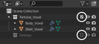
Figure 5.34 – The two tortoise collections in the Outliner with their checkboxes circled
Now that the tortoise base mesh is visible, let's add a Multiresolution modifier to the shell.
- Click on the Shell object to select it.
- Click on the blue wrench tab, in the Properties editor, to switch to the Modifiers tab.
- Click on Add Modifier and choose Multiresolution from the Generate column in the list of modifiers.
- Click on the Subdivide button twice to increase the subdivision level to 2.
Now, here's where things get tricky and a little bit confusing. We're going to duplicate the shell and shrinkwrap the duplicate onto the highly detailed tortoiseshell.
- Open the Object menu in the upper-left corner of the 3D Viewport and choose Duplicate Objects. This will duplicate the shell and begin moving the duplicate.
- Press the Esc key or right-click to cancel the movement of the duplicate shell, leaving it in its original position.
- Either double-click on the name of the duplicate shell in the Outliner or press the F2 hotkey to rename it to Shell_Shrinkwrapped:
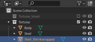
Figure 5.35 – The duplicate shell object as displayed in the Outliner
Perfect. Now we have the duplicate shell with a good topology that we can shrinkwrap to the surface of the highly detailed shell.
- Hide the original Shell object by clicking on the eyeball icon to the right-hand side of its name in the Outliner.
- Select the Shell_Shrinkwrapped object.
- Click on Add Modifier and choose Shrinkwrap from the Deform column in the list of modifiers.
Now we just need to adjust the Shrinkwrap modifier settings.
- Change Wrap Method to Project.
- Activate both the Negative and Positive projection direction checkboxes.
- Click on the drop-down list labeled Target and choose Shell_Voxel.
The final Shrinkwrap settings can be seen in the following screenshot:

Figure 5.36 – The Shrinkwrap modifier settings
We're almost there. Now we have the shell with all of the details projected onto it. This last step is a little bit awkward – we need to be able to reshape the original Shell object to match the shrinkwrapped shell. However, to do this, we need to be able to view both shells at once. Let's apply the modifiers to the Shell_Shrinkwrapped object, then we can move it to the side and unhide the original Shell object.
- Click on the drop-down arrow in the upper-right corner of the Multires modifier and choose Apply.
- Click on the drop-down arrow in the upper-right corner of the Shrinkwrap modifier and choose Apply.
- Use the Move tool from the Toolbar to move the Shell_Shrinkwrapped object off to the side.
- Unhide the original Shell object by clicking on the eyeball icon next to its name in the Outliner.
Now we should be able to view both shells at the same time. The Shell_Shrinkwrapped object will be off to one side, and the Shell object will be visible on top of the tortoise's body. This arrangement can be seen in the following diagram:

Figure 5.37 – The Shell_Shrinkwrapped object next to the Shell object
Perfect. With these two versions of the shell side by side, we can request the original Shell object's Multiresolution modifier to reshape itself to match the Shell_Shrinkwrapped object.
- First, select the Shell_Shrinkwrapped object.
- Hold Shift and click on the Shell object to add it to the selection.
- Expand the Shape subsection in the Multiresolution modifier settings.
- Click on the Reshape button.
And we're done! The shape of the shrinkwrapped shell has been transferred to the displacement of the shell's Multiresolution modifier. If you're happy with the result, we can delete both the Shell_Shrinkwrapped object and the Shell_Voxel object, as they are no longer needed.
Repeat these steps for the body of the tortoise and we'll be done.
How it works…
This takes a lot of steps, but the end result is worth it so that we don't have to resculpt any of our details. All of the details have been successfully recaptured and stored in the displacement of the Multiresolution modifier. From here, we can continue sculpting, adding more levels of subdivision, and sculpting even more details into the sculpture.
It is likely that some of the unwanted jagged edges will be captured from the original voxel version of the sculpture into the new multiresolution sculpture. If this happens, you can use the smoothing brush to clean up those areas.
This is by no means a necessary part of the process. You might even prefer to sculpt these details into the multiresolution version of the sculpture by hand instead of trying to salvage the details from the pre-multiresolution version of the model.
Either way, this model is now ready for sculpting extremely high details such as scales, skin wrinkles, sharp edges around the nostrils and mouth, and more.
There's more…
The latest version of Blender added a simplified way of applying the shrinkwrapped details to the Multiresolution modifier's displacement. The new way does not require you to create a duplicate of the object, nor does it require you to use the Reshape button. Simply, add the Shrinkwrap modifier directly to the multiresolution object and set the appropriate shrinkwrap settings that we learned about earlier. Then, click on the drop-down arrow in the upper-right corner of the Shrinkwrap modifier and choose Apply. That's all there is to it.
Changing resolution for the appropriate details
One of the hidden benefits of sculpting with the Multiresolution modifier is that we can sculpt on any level of subdivision whenever we want to. In the Voxel Remesher workflow, we have to be very strict about working from areas of low detail up to areas of high detail. However, with multiresolution, we can simply change the sculpting subdivision level and we're ready to work on a different resolution.
This doesn't come up terribly often, but it's great for fixing larger aspects of our models such as proportions, even if we've already sculpted high-resolution details. Additionally, we can take advantage of this feature to pose the character with the Pose brush.
In this section, we will try toggling between the subdivision levels to work on appropriate details and wrap up the chapter by creating a sculpture that poses.
Getting ready
Download the example tortoiseMultiresolution.blend character file at https://github.com/PacktPublishing/Sculpting-the-Blender-Way/blob/main/Chapter05/tortoiseMultiresolution.blend.
Launch Blender and open the tortoiseMultiresolution.blend file. Once you've opened the file, we can try sculpting at multiple resolutions.
How to do it…
In this file, the sculpture is a tortoise with lots of high-resolution details such as wrinkly skin and scales:

Figure 5.38 – The high-resolution tortoise sculpture
The level of detail present in this sculpture is possible because of the Multiresolution modifier. If we want to change the proportions and positions of the large forms of this character, we will have a difficult time doing so because there are nearly four million triangles at the current resolution. Let's attempt to move the front leg using the Grab brush:
- Activate the Grab brush from the Toolbar.
- Increase the radius of the brush so that it covers the majority of the tortoise's front leg:

Figure 5.39 – The Grab brush with a large size covering the front leg of the tortoise
- Press your pen to the tablet and drag to stretch the tortoise's front leg outward:
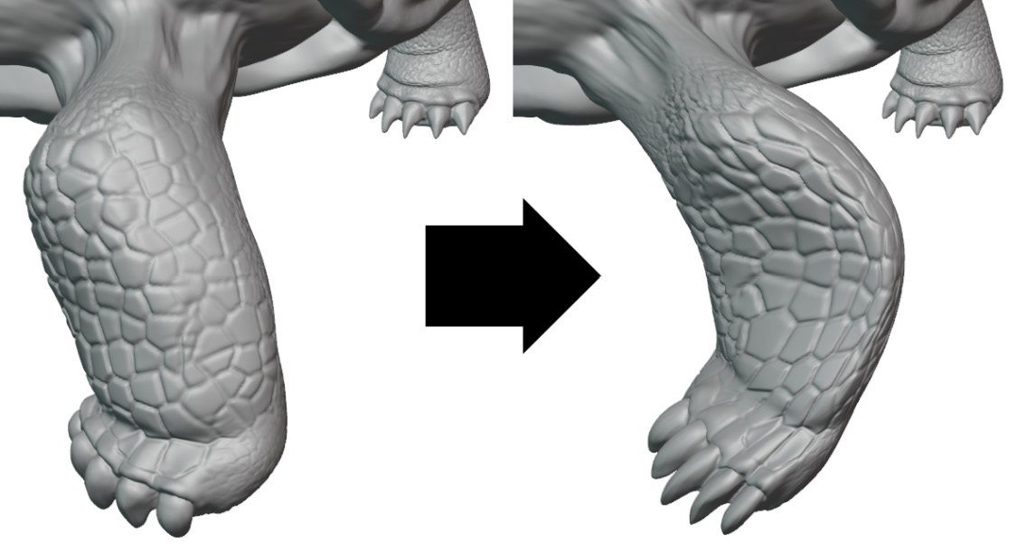
Figure 5.40 – The tortoise's leg before and after being stretched to the side via the Grab brush
Well, that didn't work very well, did it? The Grab brush has a hard time operating at this resolution because there are too many polygons. The leg didn't move uniformly, and the Grab brush put a kink in the leg's shape. Maybe we can try smoothing it out with the Smooth brush.
- Hold the Shift key to access the Smooth brush.
- Draw over the leg's surface to attempt to smooth out the kink in the leg:

Figure 5.41 – A failed attempt to fix the kink in the leg
Unfortunately, this did not work very well at all. Because of the high resolution, the smoothing brush is only able to smooth out the surface details. The scales on the leg have been erased, but we are unable to smooth out the kink in the leg's shape.
This is a job for a lower resolution! Let's restart and try again.
- Open the File menu and choose Revert to reset this file back to its previous state.
- Take a look at the settings for the Multires modifier in the Properties editor and set the Sculpt value to 0.
Most of the details have disappeared from the sculpture, but now we can sculpt on the tortoise as if the high-resolution details don't exist. Feel free to use your sculpting brushes to change the proportions of the tortoise. Try Grab, Smooth, Inflate, or any other brushes you like (it doesn't have to look good; we're just experimenting right now). In our example, we've morphed the tortoise's legs into some sort of sea turtle. Once you're happy with the new shape, change the Sculpt value in the Multires modifier back up to 3. You can view our example as follows:

Figure 5.42 – Sea turtle legs with scales intact
Isn't that fascinating? Because we did all of the sculpting on the lower resolution version, we were able to utilize our sculpting tools more freely to distort the large shapes. Then, when we toggled back up to the high-resolution version, all of the details such as the scales stayed intact. Do you feel the power of the multiresolution workflow now?
Let's try a more practical example with the same workflow. We can pose the tortoise's limbs while using the lowest resolution. Blender includes an excellent brush designed specifically for this purpose – the Pose brush:
- If you don't want to keep the changes you've made so far, open the File menu and choose Revert to reset this file back to its previous state.
- Set the Multires modifier's Sculpt value to 0.
- Activate the Pose brush from the Toolbar.
- Turn off the X axis symmetry setting by clicking on the X toggle next to the butterfly icon in the header of the 3D Viewport.
- Hover the brush over the tortoise's head.
- Do you notice the small white line extending outward from the brush? This is a unique feature of the Pose brush. It indicates where we can pivot the sculpture from.
- Increase the brush radius until the white line reaches the base of the tortoise's neck:
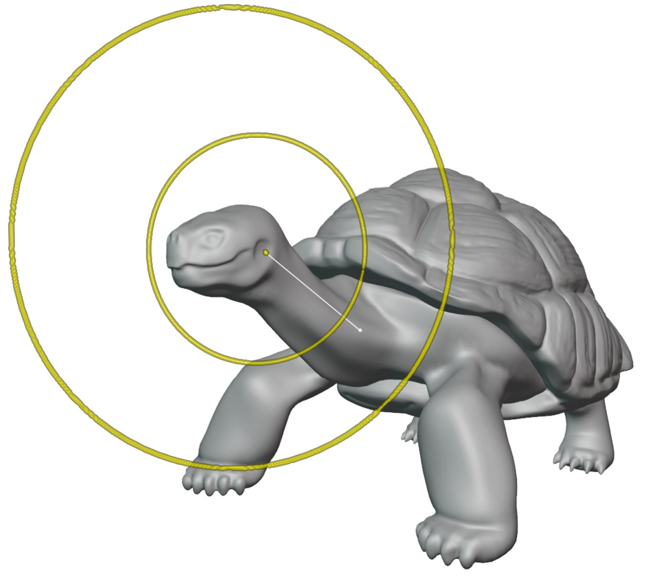
Figure 5.43 – The Pose brush reaching from the head down to the base of the neck
- Press and drag with your pen to pose the tortoise's neck.
To curve the neck, we can make a small adjustment with the current brush radius. Then, we can reduce the brush radius to make a small adjustment again. Keep repeating this until you've curved the neck into a pose that you're happy with.
- When you've got the tortoise posed the way you like, set the Multires modifier's Sculpt value back up to 3:

Figure 5.44 – The tortoise in its final pose with zero subdivision levels (on the left-hand side) and three subdivision levels (on the right-hand side)
Posed characters look a lot more natural than stiff characters do, but we often save our poses for one of the final steps in the process. This would not have been easy without the multiresolution workflow.
How it works…
The Multiresolution modifier stores all of the high-resolution details in displacements that are relative to the base mesh's topology. If we reduce the resolution, any changes we make to the lower resolutions will be propagated back up to the higher resolutions.
There's more…
Because the displacements are based on the topology of the lower resolutions, we can also slide the topology around using the Slide Relax brush. It's easier to see what you're doing if you turn on the wireframe overlay. However, this tool will allow you to slide the topology from one area to another. In the case of this turtle, we could toggle down to the lowest resolution, slide relax the topology from the lower leg up to the upper leg, then toggle back up to the high resolution to find that the high-resolution scales have moved to the upper leg.
There are numerous other great features related to multiresolution. However, this chapter should have given you the boost you need to be able to effectively create high-resolution sculptures.