
CHAPTER
Spanning Tree Attacks |
5 |
INFORMATION IN THIS CHAPTER
![]() Understanding the Spanning Tree Protocol
Understanding the Spanning Tree Protocol
![]() How Spanning Tree Attacks Work
How Spanning Tree Attacks Work
![]() Dangers of Spanning Tree Attacks
Dangers of Spanning Tree Attacks
![]() Defending against Spanning Tree Attacks
Defending against Spanning Tree Attacks
![]() The Future of Spanning Tree Attacks
The Future of Spanning Tree Attacks
In November 2002, the staff at Beth Israel Deaconess Hospital in Boston, Massachusetts, had to be retrained to use paper records. Starting on November 13, and lasting almost 4 days, the hospital’s network failed. The hospital had backup generators, second backups for those, and even batteries. They clustered their servers and performed parallel backups. They also had redundant network links, and that, sadly, caused some of the problem.
Hospitals generate and consume a lot of data in their daily operations. During this period, hospital staff, in addition to usual duties, had to ferry a quarter-million sheets of paper around the hospital. Lab results were written down, dumped in plastic bins, and delivered by runners. So, what caused this crash? It wasn’t terrorism; it wasn’t even malicious hackers in this case.
“The problem had to do with a system called Spanning Tree Protocol (STP), which finds the most efficient way to move information through the network and blocks alternate routes to prevent data from getting stuck in a loop.”1
On November 13, a researcher was uploading a large volume of data, and that triggered the underlying problem. When traffic on an Ethernet link increases, packets begin to be dropped. Among the dropped packets are those used by the STP; it starts to see the network link as “dead” and enables previously disabled links to correct the problem. A loop results, data travels around and around the loop indefinitely, and the network fails. In this case, the failure was made possible because network administrators had misconfigured their network as it had grown. The STP allows a maximum of seven “hops,” or connections, between network bridges. In some cases the hospital had 10.A
LAYERS OF THE INTERNET
Networks are built-in layers to separate concerns. Each layer hides all the details of the levels below it, so engineers working at a particular level do not have to concern themselves with the levels below. At the lowest levels, engineers work with electrical or optical fields to transmit bits between hardware units. At the highest levels application programmers send complex messages between machines. Web developers don’t want to understand Faraday rotators,B and the engineers don’t want to understand SOAP.C Who could blame either one?
The Open Systems Interconnection (OSI) Reference ModelD provides a seven-layer model for networks, ranging from transmitting bits at the physical layer to transmitting arbitrary data at the application layer. The seven layers of the OSI model are shown in Figure 5.1. We can broadly divide these layers into two classes: the ones that deal with the transmission medium (the “media” layers) and those that deal with messages being sent (the “host” layers). Ideally, each layer provides services to the layer immediately above it, and uses the services of the layer immediately below it. Examples of particular protocols in each layer are given on the right-hand side of Figure 5.1.
Of course this is all too organized and regimented, and in the world of the Internet this isn’t actually how things work. In fact, the technical document that sets forth much of the Internet’s architecture and philosophy contains a section titled “Layering Considered Harmful,” in which the authors argue that rigid layering leads to inefficiency and duplication of functionality.E It is still necessary to know a bit about the OSI reference model to understand local area network (LAN) standards such as IEEE 802.F Further, the literature will often refer to the data link layer as “layer two,” which makes little sense unless you know about the OSI reference model (and count from the bottom).
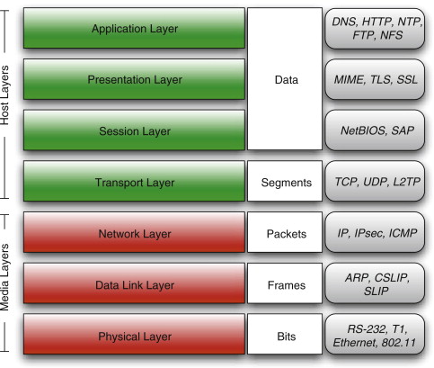
FIGURE 5.1
OSI Reference Model
The actual conceptual layering of the Internet is shown in Figure 5.2.G Note that even though some of the labels are the same, the layers aren’t perfectly analogous. At the bottom level is the link layer concerned with physical connections between hardware devices (this corresponds to the combined OSI physical and data link layers).
The link layer is responsible for transmitting frames, well-defined collections of bits. Frames contain a preamble and a start of frame marker to allow devices to synchronize correctly. They also contain a cyclic redundancy check (CRC), a checksum to allow for error detection. When a frame is received the CRC is computed and compared to the value stored in the frame. If they do not match, the receiver requests that the frame be retransmitted. The frame has a source address and a destination address, but these are not Internet host names, or even the somewhat familiar Internet Protocol (IP) addresses. This level of the Internet uses Media Access Control (MAC) addresses, 6-byte addresses uniquely assigned to hardware.H An Ethernet frame contains between 46 and 1,500 bytes of actual data, along with 26 bytes of overhead.
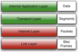
FIGURE 5.2
The Internet Protocol Suite Layers
The Internet layer is home to the IP. This is where the more familiar IP addresses are found, and where internetwork routing occurs.I The fundamental unit of communication at this layer is an IP packet. IP packets contain an IP header, specifying the source and destination IP address, and some amount of data. The packet itself is transmitted as the data component of a frame.
At the transport layer we find the Transaction Control Protocol (TCP) and User Datagram Protocol (UDP). Again we have a header for the protocol followed by the data to transmit. For TCP and UDP, this includes the source and destination ports, the length of the data, and another checksum. TCP provides for large messages to be broken up across multiple packets and reassembled in the correct order without duplication. To accomplish this, it includes a sequence number in every packet that identifies the packet’s position in the overall message.
Finally, the Internet application layer provides protocols that operate on top of the TCP, such as Hypertext Transfer Protocol (HTTP) and Secure Socket Layer (SSL). In general, people working with these protocols do not need to concern themselves with how messages are delivered; since message fragmentation, reassembly, and verification are handled at the transport layer, routing is handled at the Internet layer, and the details of sending bits from one physical device to another is handled at the link layer.
The transmission of data on Ethernet is summarized in Figure 5.3. To transmit the Hypertext Markup Language (HTML) content of a single Web page, the message is broken into chunks to be sent and reassembled by TCP. Each TCP packet becomes the data payload of an IP packet that in turn becomes the data payload of a frame. The multiple frames are then transmitted across physical links on the Internet (across a wire, across fiber, or as a wireless signal). The term “TCP/IP” is often used as a synonym for the IP suite, as these two protocols are the most commonly used.
You start your Web browser and navigate to your Star Trek blog. A ha! Your “friend” Mike has commented on your latest post, a lengthy discussion of the crossover episode from Deep Space Nine and the original Trek. You click the comment to read it. Your browser creates an HTTP request and then opens a TCP connection to send it. This creates a “flood” of TCP packets that are encapsulated as IP packets and finally as frames. The frames travel from your computer to your local network, then through your cable modem or phone line to your home Internet service provider (ISP), then out onto the wider Internet. Traveling from router to router they eventually reach the ISP hosting your blog, where the frame data is extracted and passed to the IP layer, then to the TCP layer where the fragments are reassembled in order and any missing fragments are re-requested, finally resulting in an HTTP request being passed to the ISP’s Web server. Then the process starts all over from the other side.
TIP
You can use a tool like traceroute to see the path your packets take. This utility is available under UNIX operating systems (like Solaris and Mac OS X), Linux, and Windows. On Windows the utility is named tracert and can be run from the command prompt. Watching how packets propagate can help you diagnose whether a problem is on your machine, your local network, your ISPs network, or somewhere else.J
At the time of writing, tracing the route from the University of Maryland to Google gives the output shown in Figure 5.4.K
There are several guides online explaining how to read the output of traceroute or tracert. Essentially what you see at each step is a host name or IP address, followed by “ping” times.L This is the time for a message to be acknowledged by the particular host. Higher times (in general) mean a slower connection, but you cannot always count on this. Traffic on the Internet is shaped and prioritized as it travels, and “ping” traffic may receive a low priority in from some hardware. Thus, at step 7 we see ping times of just over 53 ms, whereas at step 11 (further along) the ping times drop to under 5 ms.
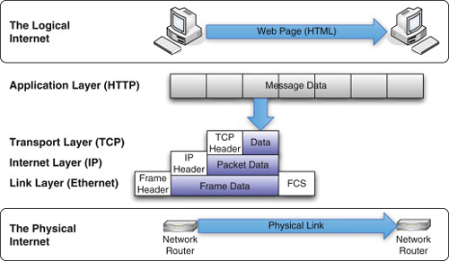
FIGURE 5.3
Sending a Web Page across Ethernet
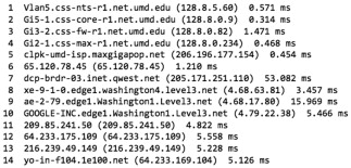
FIGURE 5.4
Traceroute Output
UNDERSTANDING THE SPANNING TREE PROTOCOL
One reason why the Internet is so reliable is that it allows for redundancy. Eventually physical hardware wears out and fails. People trip over power and network cables and “accidentally” unplug things they should not. Earthquakes and other natural disasters can destroy infrastructure. Construction workers dig up fiber-optic cables. Undersea cables are cut.M Despite all this folks, halfway around the world can still receive the wisdom of your latest blog post on six reasons why Gene Roddenberry was right the first time when he wanted to name the starship Yorktown instead of Enterprise.
Redundancy is a fundamental property of networks. Used intelligently, it allows networks to “self-heal” by detecting trouble and routing traffic around the trouble spot. This implies that there may be more than one link between any two pieces of hardware, and more than one route between any two machines. How do we choose the route a particular packet will take at any given moment?
Devices connected to the Internet can move. Are you browsing from your living room? From the coffee shop down the street? From the coffee shop next to the coffee shop down the street? From the coffee shop in an airport in a foreign country? Somehow packets intended for your machine find their way to your machine.
The Problem of Loops
This process of route discovery and packet routing takes place at several levels of the Internet, but we are concerned here with the link layer. Consider Figure 5.5. The machine Alice has MAC address 00:00:00:00:00:01, while the machine Bob has MAC address 00:00:00:00:00:02. Two switches connect these machines: switch X and switch Y. Each switch has three ports, named p0, p1, and p2 on switch X, and q0, q1, and q2 on switch Y. We want to send a frame from Alice to Bob.
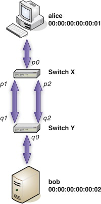
FIGURE 5.5
A Redundant Connection
Router? Switch? Hub? What’s the difference? Hubs allow multiple devices to share a single line. Switches connect machines to form networks. Routers connect entire networks.
A hub connects multiple Ethernet lies to a single line, essentially creating a party line. At most one machine can talk on the line at a time. If two or more machines try to talk at the same time, we have a collision, and both must stop sending, wait a random amount of time, and then talk if the line appears to be idle. Essentially a hub is a dumb backbone that connects multiple lines to a single line.
This situation can be improved using a switch that accepts frames from every port, determines the appropriate output port for each frame, and then transmits the frame on that port. A switch connects multiple lines to each other. Multiple machines can communicate at the same time, an improvement over the hub. Because this situation is more complex, switches require special internal logic to keep track of the appropriate port for each frame. Some switches also provide security and configuration features.
A router connects networks. This is a significantly harder job, and thus routers are more complex (and more expensive) than switches. One side of a router may be an Ethernet cable, whereas on the other side there may be a Ethernet cable, phone line, serial cable, or something else. Routers often provide a rich set of configuration and security options.
To return to the OSI model, we can say that hubs operate at the physical layer (layer one). Switches operate at the data link layer (layer two). Routers operate at the network layer (layer three).
As a final note, be aware that these terms are not always used correctly. Sometimes what someone calls a “hub” is actually a switch or even a router. Fortunately you will never make that mistake.
To simplify this discussion, we will use the machine names instead of the MAC addresses. Keep in mind that the frames contain the MAC addresses, and not the names! When a frame arrives at a switch, we examine the frame’s source and destination addresses. Initially the frame from Alice arrives at switch X, on port p0, with destination Bob. From this switch X learns that Alice is on port p0. It does not yet know where to find Bob, so it sends the frame out on all ports (this is called flooding), except the port on which it received the frame. The frame is sent on p1 and p2.
Now switch Y receives the frame from Alice to Bob, but we have a race condition. The frame might arrive on either port q1 or port q2 first. Switch Y doesn’t “know” that both ports connect to the same switch; they might connect to anything, and these connections might even be changed. Suppose the frame arrives on port q1 first. From this frame switch Y discovers that Alice is on port q1. It doesn’t know where to find Bob, either, so it also floods the frame to ports q0 and q2. Next the same frame arrives on port q2, and the process is repeated.
Meanwhile the frame from Alice to Bob arrives back at switch X on port p2. From this switch X concludes that Alice must be on port p2. It floods ports p0 and p1, and the whole process continues. These frames continue to travel around the loop created by the redundant connection. When Bob finally replies, it is too late; a perpetual loop has been created that causes the switches to constantly update their internal tables with bad information.
To avoid this condition, we need to disable one of the redundant links between the switches. Fortunately, Radia Perlman solved this problem in 1985 with the introduction of the STP,N and this became an IEEE standard in 1990.O This is a combination of an algorithm and a Link Layer Protocol that creates a loop-free view of the network. Certain redundant paths are disabled but can be re-enabled automatically if needed (so the network retains its redundancy).
Solving the Loop Problem With the Spanning Tree Protocol
In mathematical graph theory, a spanning tree of a graph is a subset of the graph such that all nodes are connected and there are no loops. Translated to the world of networks, a network spanning tree is a subset of all the network links such that no loops are formed. Returning to Figure 5.5, one way to create a spanning tree is to disable the link between p2 and q2. Now when a frame from Alice to Bob arrives at switch X, it is sent on the link from p1 to q1. The frame arrives at switch Y, which sends it out on port q0, where Bob receives the frame. Once Bob replies, the switch tables are set as shown in Tables 5.1 and 5.2. Subsequent frames are immediately sent to the correct port (no need for flooding).
It is obvious to us which links to cut in Figure 5.5 to create a loop-free path because we have a small network and we can see it all at once. The individual switches cannot “see” the network, so they need a means to communicate among themselves, determine what paths are redundant, and agree which ones to disable.
When discussing the STP, devices that connect network links are called bridges. They may be routers, switches, wireless access points, or other machines that act as routers or switches. Bridges in a network use special frames called bridge protocol data units (BPDU frames) to exchange information as they try to compute the spanning tree. Three kinds of BPDU frames are typically used:
Table 5.1 Switch X table |
|
Switch X |
|
00:00:00:00:00:01 (Alice) |
p0 |
00:00:00:00:00:02 (Bob) |
p1 |
Table 5.2 Switch Y table |
|
Switch Y |
|
00:00:00:00:00:01 (Alice) |
q1 |
00:00:00:00:00:02 (Bob) |
q0 |
• A configuration BPDU (CBPDU) is used to compute the spanning tree.
• A topology change notification (TCN) BPDU is used to announce changes in the network’s structure (such as when links are added or removed).
• A topology change notification acknowledgment (TCA) BPDU is used to respond to TCN frames and confirms their receipt.
BPDU frames are always being exchanged (usually every 2 seconds, called the hello interval) to keep the network information up to date.
To centralize information about the network, a particular bridge is selected and made the root bridge. This bridge coordinates updates to the network structure. The first task of STP is to select the root bridge. Every bridge has a 2-byte priority assigned to it (a number in the range 0 to 65,535). The network administrator can change this priority. Every bridge also has a unique 6-byte MAC address. The combination of these two numbers is the 8-byte bridge identifier (BID).P This is used to determine the root bridge in the following manner: the bridge with the lowest priority is the root bridge. If two or more bridges have equal priority, then the bridge with the lowest MAC address will be the root bridge.
The implementation of this is simple: every bridge floods a BPDU containing its BID and announcing that it is the root bridge.Q If a bridge receives a frame with a lower BID, then it knows it cannot be the root bridge, and it stops generating these frames. Otherwise it continues, since it may be the root bridge. Ultimately only one bridge is generating frames claiming to be the root bridge: the bridge with the lowest BID.
Every other bridge needs a unique path to the root bridge. Because communication with the root bridge is frequent, this path should be a least-cost path. The cost of traversing a link is determined by the version of the STP protocol in use, the data rate, and the settings applied by the network administrator. Once the root bridge has been chosen, every other bridge computes the cost of each path from itself to the root, and chooses the least-cost path. The port that corresponds to the least-cost path is known as the root port. For each network link the bridges on the ends of the link determine which of them has the least-cost path to the root. The port connecting the least-cost bridge to the network link becomes the designated port for that particular link. After the costs are computed and bridge and designated ports are chosen, all other ports are blocked. At this point, the loop-free network has been created.
Again, the implementation of this is fairly simple. Every BPDU contains an accumulated cost. BPDU frames sent from the root bridge have their cost set to zero. Whenever a bridge receives a BPDU frame, it adds the cost associated with the port to that frame’s cost before passing it along. When BPDU frames are received on multiple ports by a bridge, the ports receiving the highest-cost frames are placed in blocked state, logically disabling them. This process converges (quickly or slowly, depending on many factors, but typically in under a minute) to the loop-free spanning tree.
It is possible to have ties. Multiple paths might have identical (lowest) cost. In this case the path connecting to the lowest BID is chosen. For a particular network link, multiple bridges on the link might have identical (lowest) cost. Again, these ties are broken in favor of the lowest BID. Finally, as in Figure 5.5, there may be multiple links joining two bridges. In this case, the lowest port priority wins (ports on a switch are assigned unique priorities).
From the point of view of a particular port, the process looks something like the following: initially the port is turned off, or disabled. When it is turned on (because its bridge is connected and turned on) it transitions to the blocked state, where it discards all traffic except BPDU frames. The port then listens to the BPDU frames as described earlier to identify the root bridge and build the loop-free network. A port may be learning about the network. In this state data frames are not forwarded, but they are examined to build the routing table. Finally, a port may be forwarding, in which case data frames received are routed along, and the port is “fully open.” Ports transition from listening and learning states to forwarding states after a specified forwarding delay.
After this initial creation of a loop-free network, BPDU frames continue to be exchanged (at every hello interval) to account for updates in the network, such as a port or link failure or the addition of new hardware. It is possible, for instance, that a new switch will be added that has a BID lower than the current root bridge. It is also possible that a network administrator will alter the priorities of existing bridges. In these cases, the spanning tree must be recomputed. It is this process that can be hijacked by an intruder to cause mischief.
Finally, TCN frames are sent whenever a bridge observes a link or port being enabled or disabled. These frames are forwarded to the root bridge (so they are seen by all bridges along the path to the root), and every bridge along the way acknowledges the TCN with a TCA. This allows the necessary reconfiguration of the network when a link fails or is added, and preserves redundancy and resiliency of the network.
In a network that has converged to a loop-free state so that ports are forwarding traffic, the root bridge continues to send BPDU frames at every hello interval. These frames contain an “age” field that is initialized to zero by the root bridge and set to the time of transit of the frame as it makes its way through the network. When another bridge receives one of these frames on a port, it initializes an internal clock for that port to the provided age and begins counting up. For example, if the age is 5 seconds, the port clock will start counting from 5 seconds. If the timer reaches the configured maximum age (typically 20 seconds), then the bridge assumes that connectivity may have failed and restarts the election process for the root bridge by announcing that it is the root (the first step of the election process). After all, it is possible that the old root bridge has failed. Once the boss has left the building someone has to be in charge. Why not you?
HOW SPANNING TREE ATTACKS WORK
An attacker who is physically connected to your network and who has the ability to create BPDU frames with specific characteristics can use the STP to cause various kinds of havoc, from stealing data to disrupting your network (a denial of service, as described in Chapter 1, “Denial of Service”). This section describes how some of these attacks can be accomplished.
“Ah ha!” you may say. “You said ‘physically connected.’ We’re totally secure.” Well, maybe. First, there is always the risk of a malicious insider. That is, someone who routinely has access to your hardware might not be entirely without guile.R Second, wireless access points can broadcast BPDU frames and participate in the STP. By listening for these frames (typically broadcast by a misconfigured wireless access point), an intruder can obtain information about the network and inject their own forged BPDU frames to cause havoc. Third, have you read the rest of this book? If an attacker sitting comfortably in their parents’ basement hundreds of miles away breaks into your network and compromises a machine, then they have a machine physically connected to your network.
Another element to note is that sometimes you have no option but to allow people to physically connect to your network. Hotels and universities, for instance, typically provide direct physical connections for guests and students, respectively. “Guests and students” covers a lot of humanity. It is worth taking steps to protect your level 2 infrastructures, as everything else is built on top of them.
Capturing BPDU Traffic
Some of the attacks described here require capturing some of the BPDU frames and examining them to determine, for instance, the current root bridge’s BID. This section presents two tools to help you do this: tcpdump and Wireshark, both of which were also discussed (very briefly) in Chapter 1, “Denial of Service.” Another tool, Yersinia, is described in the section Forging BPDU Packets.
tcpdump
The workhorse for capturing packets crossing an interface of your computer is a program called tcpdump.S This is a command-line utility for capturing and examining packets on a network interface. While tcpdump is a UNIX/Linux program, it has been ported to Windows as WinDump.T In addition, you can use the packet capture facilities of tcpdump via its companion library, libpcap.
Using tcpdump is a good way to learn about a network. You can watch all the traffic, or select just certain kinds of packets to display. The full details of using tcpdump are beyond the scope of this chapter, but the following is a quick example of using tcpdump to examine STP traffic.
  $ tcpdump -c 1 -i en0 stp
  listening on en0, link-type EN10MB (Ethernet), capture size 65535
     bytes
  02:28:55.673633 STP 802.1w, Rapid STP, Flags [Learn, Forward,
     Agreement], bridge-id 8000.00:01:23:45:67:89.803a, length 47
Here we have told tcpdump to examine traffic on the first Ethernet interface of our OS X-based Mac (-i en0) and to capture just one packet and stop (-c 1). We are only interested in STP-related traffic, so we include the stp filter at the end of the command. The output consists of several pieces of information. The first part of the output is a time stamp (02:28:55.673633) indicating a time of 2:28 A.M. (a good time to be up hacking). Following this we see that this packet is using the STP version defined by IEEE standard 802.1w, otherwise known as the Rapid Spanning Tree Protocol (RSTP). This is a version of the protocol that responds to topology changes (links being added and removed) much faster than the original STP standard. We are told about the port flags (the port is learning MAC addresses and forwarding frames) and the BID. The bridge has MAC address 00:01:23:45:67:89 and hexadecimal priority 8000 (or 32,768 decimal). This is the default bridge priority, and you are likely to see it for most of the bridges you encounter in a network.
Additional switches will cause tcpdump to generate even more detailed information, including a list of the value of every byte of the frame. Depending on where your machine is sitting in the network (you are acting as a switch, or are a PC sitting at an endpoint) you may see traffic from just one or perhaps several bridges.
Wireshark
Although tcpdump is powerful and effective (and you really should know how to use it and read its output), it is a command-line tool with a lot of cryptic switches. Can’t someone package all this up in a nice graphical user interface (GUI)? Formerly known as Ethereal, WiresharkU is a program for capturing and decoding packets on a network interface, just as with tcpdump. Unlike tcpdump, however, Wireshark allows you to perform captures from within a (relatively) comfortable GUI. The Wireshark GUI at startup (running under Linux in this case) is shown in Figure 5.6.
Wireshark is very useful if you are trying to understand a Network Protocol. Figure 5.7 shows a packet capture filtered to just show STP packets (this time running on an Apple Mac). At the top of the window is the list of packets captured, each of which is decoded. In this list, the MAC address is decoded to show the OUI (in this case the MAC is registered to 3com), followed by the unique device address. In the middle section the parts of the frame are broken out hierarchically, and decoded. In the figure, the BPDU flags section is selected, showing how the bits (01111100 in binary) are decoded. At the bottom the raw frame data is shown in hexadecimal. Since the flags section is selected, the byte containing those bits is highlighted (7C in hexadecimal). This kind of information is invaluable if you are trying to observe, understand, and then exploit a protocol.
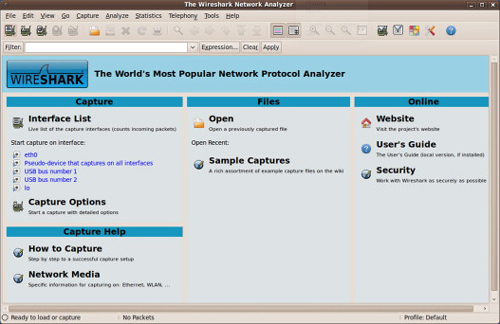
FIGURE 5.6
Wireshark
Taking over the Root Bridge
So what can you do with the STP? One fun activity is to make your machine the root bridge. Doing this is not really hard, you simply need to forge a BPDU frame with BID that will win the root election. Remember that STP uses the bridge MAC address and the bridge priority to determine who should be the root bridge. Thus if you can detect the current root bridge and send a frame with the same priority but a lower MAC address, you will become the new root bridge.
For example, you might fire up Wireshark and observe STP packets for a while. As you see in Figure 5.7, the root bridge is identified, and its priority and MAC address are displayed. Suppose you see that the root bridge has priority 32,768 (the default priority) and MAC address 00:01:23:45:67:89. Now to become the root bridge and win the next election you can broadcast BPDU status frames with a priority of 32,768 and a forged, or “spoofed” MAC address of 00:01:23:45:67:88. This lower MAC address guarantees that you will win the next election to become the root bridge. You should send these frames every 2 seconds (the “hello” interval). Of course, if you are feeling adventurous you might just set the priority to 0 and the MAC address to 00:00:00:00:00:00. In some cases this will work, too.
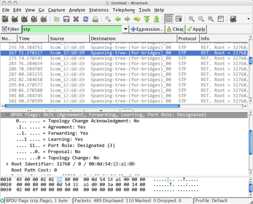
FIGURE 5.7
STP Packet Capture in Wireshark
Denial of Service
Now that you own the root bridge, what’s next? Well, recall that the root bridge is responsible for sending out BPDU frames at every hello interval. One possibility is simply to not do that, and wait for another root bridge election. When the election happens (you receive BPDU frames from a neighbor asserting themselves as the root bridge) you immediately assert yourself as root again, and win. If the maximum age is low enough and you repeat this process, you can keep the network from converging and disrupt traffic, an effective denial of service attack. An alternative is to remain the root bridge, but never send a TCA when a TCN is received. In this case, a switch’s forwarding table ages rapidly and the switch must flood its ports.
There is nothing preventing you from claiming the root role and then sending BPDU configuration frames to surrender the root role. For example, you can claim the root role, then raise your priority to let the prior root win. Then immediately reclaim the root role. Again, this is very disruptive. If you time it correctly (and this depends to some extent on the particular timer values for the network—which you can see using Wireshark), you can keep several of the switches from ever transitioning their ports to a forwarding state.
Since you are lying about your MAC address, you might as well lie often. Watch for a BPDU from the current root, and then start sending BPDU frames with a MAC address one lower at the same priority. You’ll win the election and become the root bridge. Now immediately decrement the MAC address and repeat. You’ll become the root bridge again, but since the MAC address is different it is as if another physical machine were becoming the root bridge. Every switch must recompute its path to root and costs. Now decrement the MAC address and repeat. If you reach the lowest MAC address possible (00:00:00:00:00:00), return to the first value you used and start the cycle over. In this manner, you will keep the network in a state of eternal elections and prevent it from ever converging and transmitting traffic.
Man in the Middle
Sure, denial of service is fun and all, but what you really want to do is steal data. Depending on how much access you have in the network, you may be able to do just that. Remember that STP is responsible for determining which links are blocked and which are active. Since data travels only on active links, you may be able to create a situation in which most or all of the network traffic you care about is routed through your machine. You can then capture it (using tcpdump, Wireshark, or a custom program built using libpcap) and sift through it at your leisure.
Doing this requires having connections to two switches such that the data you want is going to be passing between them. This situation is shown in Figure 5.8. Here traffic between Alice and Bob typically passes between switches A and B (not necessarily a direct link). The intruder connects to the physical network (not necessarily directly to switches A and B) such that he or she has an alternate route between Alice and Bob, and then begins sending BPDU frames so that his or her ports become the designated ports for traffic. This would create a loop, but fortunately STP steps in and all other links between switches A and B are disabled. Now all traffic between Alice and Bob will be routed through the intruder’s machine.
The important thing to realize about this attack is that if the intruder has sufficient knowledge of the network, then they do not necessarily have to have direct access to switches A and B to pull this off. The intruder simply has to generate a configuration that results in the path through it winning over the direct path from A to B. After all, if the intruder did have direct access to the two switches, they might be able to simply physically insert themselves by plugging and unplugging cables.
One way to accomplish this is shown in Figure 5.9. Here the intruder has access to two other bridges: C and D. (It is even possible these could be wireless access points that have been misconfigured to forward BPDU frames.) The attacker claims the root bridge role, and now every bridge computes the least-cost path to the root. The least-cost paths from C and D are most likely the direct links, and thus cannot be blocked. Thus, any other link between A and B and any other link between C and D must be blocked to prevent cycles. Now the intruder is free to watch the traffic.
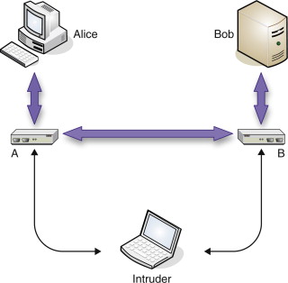
FIGURE 5.8
Man in the Middle Attack
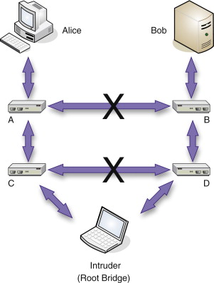
FIGURE 5.9
Alternate Man in the Middle Attack
Forging BPDU Frames
The key to hijacking the STP is forging BPDU frames. If you can construct and send BPDU frames with specific characteristics, you can cause havoc with the protocol because layer two is essentially security-free.
If you are a programmer, you can use the libnet libraryV to construct and send BPDU frames. This is a networking library that lets you programmatically access several protocols. Libnet is a relatively low-level library, allowing you to specially craft and then send packets. For example, you might create and send configuration STP packets (BPDU frames) in an attempt to claim the root bridge role for yourself. Using libnet requires that you write a program. While libnet is a C library, helpful people have created other interfaces to it, including a Perl libraryW and Python library.X In short, the library is highly available.
Of course, this is the twenty-first century, and you’ve got other things to think about. Can’t someone else do the work for you? Of course they can. A whole variety of layer 2 attacks (not just spanning tree attacks) is available using a tool called Yersinia,Y a freely available, open-source tool for launching certain network protocol attacks, including against STP. At the time of writing, Yersinia has a “curses” interface (that is, it has a text-based GUI), but an even nicer GUI is in development. After all, STP is already hard enough, isn’t it? The Yersinia GUI is shown in Figure 5.10. Note that while Yersinia runs under Linux and UNIX (including Mac OS X), it is not available for Windows at the time of writing.
Now that you have Yersinia, you are ready to launch some attacks. Pressing h brings up the quick help, and pressing x brings up the list of available attacks (shown in Figure 5.10). Note that at the bottom of the display is a list of the STP fields. These can be edited directly by typing e, and allow you to craft whatever STP packet you wish. Also note that you can explicitly claim the root bridge role or relinquish it (“claiming other role”) from this interface, as well as launch a variety of denial of service attacks (those attacks with an X in the DoS column). There really isn’t much more to it.
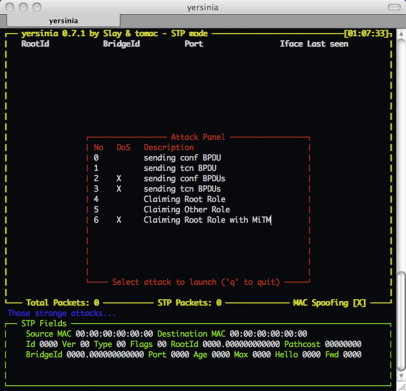
FIGURE 5.10
Yersinia’s Text-based GUI
WARNING
You may be tempted to experiment with these tools on your home network. You might even be tempted to experiment with them on your ISP’s network, or your work network. Unless you are a network administrator or you are performing penetration testing, you might want to be careful. Many networks are monitored for aggressive port scanning, and it probably violates the terms of service. Technologies like BPDU guard (explained later) can actually result in your connection being severed and requiring a manual reset.
Discovering the Network
How does an attacker come to understand your network topology? For that matter, how can you keep track of it? Using libpcap, you can capture network traffic and analyze it to try to deduce a network topology. If that sounds like programming, take heart: someone has built tools to do this for you.
One useful tool is EtherApe.Z If you can collect packets (using tcpdump or Wireshark), you can even use EtherApe offline. The trick is to find machines that give you a good view of the network, and capture packets on those machines. You can then use EtherApe with the captured packet files to see the overall structure of the network and plan your attack (or defense). Figure 5.11 shows EtherApe running. The circles are network nodes (their size is related to the amount of traffic), and the lines are particular directed flows (their width is related to the amount of traffic). Colors are used on the interface to indicate particular protocols.
You can capture traffic using tcpdump and then use EtherApe to visualize this traffic. To do this, you need to run tcpdump with the –n flag (to prevent name resolution) and the –w flag (to specify a capture file). The following is an example.
$ tcpdump -n -c 1000 -w network.pcap
This will capture 1,000 packets and write them to the network.pcap file. You can then tell EtherApe to read this file as input (instead of trying to read network traffic on the local machine) via the –r switch.
$ etherape -F -z -r network.pcap
EtherApe is designed to watch traffic in near real time. The –F indicates that old traffic lines should not fade, and the –z indicates that EtherApe shouldn’t replay the traffic using the time stamps, but just display the diagram. Note that you can configure EtherApe to display only data from a particular protocol layer, such as the link layer (layer two), which is what is being shown in Figure 5.11. EtherApe does not attempt to show you the network topology, per se, but it does show you flows in the network and does help you discover other hosts.
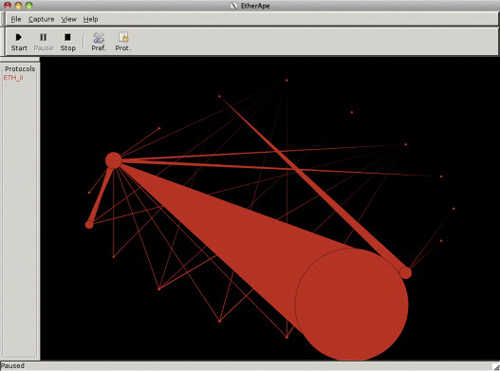
FIGURE 5.11
EtherApe
Nmap is an open-source network-mapping tool. Nmap provides a GUI called Zenmap that can help visualize your network. Unlike EtherApe, you give Nmap a list of hosts to scan, and it builds its data by actively scanning the hosts (instead of passively sniffing packets). This allows you to detect not only what hosts are available, but in many cases what the hosts do, as Nmap gives you a list of interesting ports that are open on the host. The Zenmap GUI provides the “topology” view shown in Figure 5.12. The Nmap tool is described in Chapter 1, “Denial of Service.”
There are other utilities, as well, including commercial utilities like Lumeta’s IPsonarAA and SolarWinds LANsurveyor,BB and freeware applications like LanToplog.CC
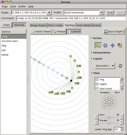
FIGURE 5.12
Zenmap’s Topology View
DANGERS OF SPANNING TREE ATTACKS
Spanning tree attacks can cause havoc at the link level of your network. This is very disruptive; switches can stop sending any packets at all, so it becomes difficult to get information from network monitoring software.
If intruders can insert themselves into your network and capture packets, they can subvert many network security assumptions. Some organizations use unencrypted e-mail connections with clear-text authentication. After all, it is impossible to connect to the mail server unless one is physically connected to the network or connected using an encrypted virtual private network (VPN) connection. Of course, an attacker who can manipulate the spanning tree to observe all packets can then capture e-mail account passwords. Do you use different passwords for all your accounts? Do your system administrators send you certificates and keys via e-mail?
EPIC FAIL |
The Beth Israel Deaconess Hospital failure is a very interesting case study. In particular, it is worth considering the actions of the network administrators as they tried to alleviate the problem. |
When network administrators noticed the network acting sluggishly they decided to act in a very “reasonable” fashion; they would shut down switches one by one until they located the source of the trouble. If the network trouble cleared up, then they would have localized the problem and could diagnose and fix it. |
As they shut down switches, they forced the recalculation of the spanning tree. The switches were now spending all their time recalculating the spanning tree, and never entering the forwarding state. The network stopped routing any traffic except the layer 2 packets. The situation was not simply reversible. Turning all switches back on did not restore the previous network state; it created a situation in which the network would sometimes route traffic, and sometimes not route traffic at all. |
Finally, the network admins diagnosed the problem as a loop in the STP. They began shutting down redundant links in the network to restore order. As they worked late into the night, the network settled down. The problem was fixed…until the next day. |
The network had begun routing traffic, it turns out, because it was late at night and very few people were using it. The next morning as hospital activity increased, the network resumed its chaotic working/slow/dead cycle. As the day went on the network admins kept trying reasonable tactics to restore the network, always feeling they were just about to fix the problem. The hospital had to shut down its emergency room. All over the hospital critical lab reports were delayed. Knowing that the network admins were “just about to fix the problem” wasn’t helping. The hospital management team essentially declared an emergency, and called Cisco Systems. |
Cisco set up a command center at the hospital and began an aggressive plan to solve the problem. From 6 P.M. until 9 A.M. the next day, the Cisco team worked to diagnose the problem, and eventually found the problematic loop. New hardware was delivered, and the network rebuilt, again working late into the night. The problem was fixed—until the next day. |
It took a few more days to restore the network, as more loops were found and fixed. There are many lessons to be taken from this case, ranging from keeping up-to-date physical and logical network diagrams to planning for eating and sleeping arrangements for your network team in the event of a disaster.DD |
DEFENDING AGAINST SPANNING TREE ATTACKS
Unlike the other attacks described in this book, spanning tree attacks require that the attacker have access to a machine physically connected to your network. Thus, the first line of defense is to make sure that all your network hardware is properly configured and that only those people who need access to the hardware have access. Next, you need to take steps to prevent intruders from gaining remote access to your network, as remote access is the next best thing to being there. Finally, it is worth observing your network from time to time to see what is actually happening. You can use the Cisco IOS show spanning-tree command for this purpose.
Disable STP
One simple approach is to disable STP when it is not needed. For example, if you have a physically loop-free network (and thus no redundancy), you have no need for STP. Small networks using a single switch, or just a few switches without any physical loops, can have STP disabled altogether. Of course since your network has no redundant loops, failure of a single link may cause complete failure of some portion of your network.
An alternative is to allow redundant network connections between switches, but to use link aggregation instead of STP. Link aggregation has been implemented by many different vendors, and so it goes by many different names, including network interface card (NIC) teaming, port teaming, link bundling, NIC bonding, and network fault tolerance, to name a few. Fortunately, the IEEE has published a standard for link aggregationEE and modern hardware conforms. Of course, you are restricted in how you connect the network.
Root Guard and BPDU Guard
Cisco supports protection systems called root guard and BPDU guard.FF These allow one to enforce a perimeter around a network to prevent STP attacks.
Root guard is enabled and disabled on a per-port basis. Enabling root guard on a port prevents that port from becoming the root port; it may only be a designated port. When an intruder sends “superior” BPDU configuration frames attempting to claim the root bridge role, the root guard protected port is placed in a “root inconsistent” state, during which it listens but does not forward traffic – it is blocked. Once the superior frames stop arriving, the port transitions to learning and finally to forwarding. If the superior frames start arriving again the port is blocked again.
This assures that the root bridge can never be located off of a port with root guard enabled. By correctly configuring ports with root guard, the network administrator can define the network perimeter and prevent stealing the root bridge role.
BPDU guard is another Cisco technology for defining a network perimeter and protecting against STP attacks. Like root guard, BPDU guard is enabled or disabled on a port-by-port basis. BPDU guard operates in a much more strict fashion than root guard: if a BPDU frame arrives then the port is transitioned to an “error disable” (blocked) state and generates a message about the event. Unlike root guard, the port does not automatically transition back to a forwarding state as soon as possible, but remains in the blocked state until either the state is manually cleared or an automatic recovery timer expires. Automatic recovery requires a minimum of 30 seconds, making denial of service attacks impractical. BPDU guard allows the network administrator to establish the limits of the STP protocol, so that BPDU frames are simply not accepted outside a defined perimeter.
BPDU guard is a good choice for ports where endpoints (workstations, printers and servers) are going to be attacked, since these devices should not be sending BPDU frames at all, unless they are explicitly configured to act as a router. BPDU guard is often combined with the portfast setting, which instructs a port to skip the listening and learning states and move directly to forwarding. Again, this makes sense for ports where endpoints that do not send BPDU frames are going to be located.
THE FUTURE OF SPANNING TREE ATTACKS
Root guard and BPDU guard are both very effective strategies to mitigate STP attacks but are both (at the time of writing) limited to Cisco hardware. These technologies may still allow an intruder to monitor BPDU frames and use these to discover network information. Once you have established a perimeter, the intruder may seek to compromise a device inside the perimeter. By capturing frames, an intruder can obtain the MAC addresses of devices inside the perimeter. By using other layer 2 attacks, the attacker may be able to compromise a device inside the perimeter and then launch an STP-based attack such as a denial of service.
Many different versions of STP exist with proprietary extensions, such as the portfast extension mentioned previously. It may be possible to exploit these extensions in ways not described here. If an intruder can set all ports to forward then they can force cycles and trigger a denial of service. Many switch implementations provide diagnostic settings that copy traffic from all ports to a single port, making it much easier to monitor and steal data.
STP attacks are themselves relatively new, having been initially proposed in PhrackGG magazine in 2002, and investigated at Black Hat EuropeHH in 2005 with the introduction of Yersinia. Because of this it is likely that intruders have not yet begun to take full advantage of STP-based attacks. We can expect this sort of attack to become more prevalent.
SUMMARY
Because layer two in general, and the STP in particular, have no inherent security, layer 2 attacks will continue and pose a serious risk to network security. Other protocols exist at layer two and these can also be exploited; many of these exploits are already implemented in Yersinia. Since layer two creates the foundation for your entire network, any trouble on this level can be difficult to diagnose and can manifest itself in several ways. The incident detailed at the start of this chapter illustrates the trouble that can arise, or that an intruder can cause, using a layer 2 protocol such as STP.
This chapter explained what layer two is and investigated STP in particular. You should understand the basics of how STP operates, and how you can exploit it for denial of service and other attacks. Finally, you should understand the role of layer 2 security and the steps you can take to defend against STP exploits.
Endnote
1. Anne B. Got Paper? Beth Israel Deaconess Copes with a Massive Computer Crash. Boston Globe, November 26, 2002.
AFor a lot of detail on this, see Edwin Hoffman, “All Systems Down – Reprise (Case Study CS401),” Raptor Networks Technology, Inc. At the time of writing this document is available from http://truebit.nl/Raptor/PDF/CS401.pdf.
BYes, it’s a real thing. This is used to prevent light from “leaking” (because of reflection) backward through a link by changing its phase angle, thus creating an optical isolator, or “optical diode.” You’re welcome.
CSOAP is the simple object access protocol that runs (typically) atop HTTP and provides a way to pass structured data to Web services and decode the reply. For more information visit www.w3.org/TR/soap/.
DHubert Zimmermann, “OSI Reference Model – The ISO Model for Architecture for Open Systems Interconnection,” IEEE Transactions on Communications, vol. 28, no. 4, April 1980, pp. 425–32.
ERFC 3439, Section 3. A “requests for comments” (RFC) can be obtained from several sites on the Web, including www.ietf.org/rfc.html.
FIEEE 802 is actually a collection of standards. The Institute of Electrical and Electronics Engineers (IEEE) publishes a variety of standards for LAN and metropolitan area networks (MAN), including the well-known 802.3 for Ethernet and 802.11 a/b/g/n for wireless networks. There are many others in the collection, including specification for cable modems and Bluetooth. Visit www.ieee.org/web/standards/home for more information.
GSee RFC 1122 and RFC 1123.
HYou’ve probably seen these. They consist of strings of the form 01:23:45:67:89:AB. Chunks of this address space are broken out and assigned to device manufacturers and other organizations. For instance, addresses starting 00:1B:63 are assigned to Apple Computer, Inc. The IEEE maintains this mapping. Visit http://standards.ieee.org/regauth/oui/index.shtml.
IIP addresses are those strings of four numbers traditionally separated by periods, such as 127.0.0.1. These are discussed in section two of Chapter 1, “Denial of Service.” Mapping between IP addresses and host names, such as google.com, is handled by the Domain Name Service (DNS), an application-layer protocol.
JYou can run traceroute from other machines and see what route is taken. The site www.traceroute.org/ hosts a collection of links to servers that provide publicly available traceroute functionality.
KSee the University of Maryland’s publicly available traceroute facility at http://noc.net.umd.edu/cgibin/traceroute/trace. A list of public traceroute servers is available from www.traceroute.org/.
LThe actual implementation can use UDP packets or Internet control message protocol (ICMP) packets. The first is more common on UNIX, and the second is the method used by tracert on Windows at the time of writing.
MSeveral undersea cables supplying Internet to countries in the Middle East were cut in 2008. So many, in fact, that suspicion arose as to whether someone was deliberately trying to disconnect these countries. See this article in Wired (retrieved November 3, 2009): www.wired.com/threatlevel/2008/12/mediterranean-c/. Because of the Internet’s redundancy these cuts degrade service, but do not necessarily deny it. Satellite links and alternate routing can be used. See also this article on Engaget (retrieved November 3, 2009): www.engadget.com/2008/02/05/fourth-undersea-cable-cut-near-uae-suspicions-rise/.
NPerlman, R., “An Algorithm for Distributed Computation of a Spanning Tree in an Extended LAN,” ACM SIGCOMM Computer Communication Review, volume 15, number 4, pages 44–53, 1985.
OIEEE 802.1D.
PLike nearly everything in the world of networking, this is all true, except when it isn’t. The introduction of the virtual LAN (VLAN) changes many elements of this, and the protocol itself has undergone revisions and modifications to make it faster and to add proprietary information. Covering all these details would require a much longer chapter. Still, the basic implementation of the algorithm (find a root bridge, compute the lowest-cost paths, etc.) remains the same.
QFrames have a destination and source. The source is the MAC address of the sender, and the destination is a special MAC address reserved for broadcast BPDU. The particular address depends on the particular standard being used, but the IEEE STP standard specifies 01:80:C2:00:00:00.
RVisit www.cert.org/insider_threat/ for CERT’s research on insider threat, and also http://www.thei3p.org/research/insider_threat.html for the Institute for Information Infrastructure Protection.
SSee www.tcpdump.org/ for both tcpdump and libpcap.
TSee www.winpcap.org/windump/.
USee www.wireshark.org/.
VSee http://libnet.sourceforge.net/.
WFor Perl, see www.perl.org/. The Perl interface to libnet is Net::Libnet; see http://search.cpan.org/~smpeters/Net-Libnet-0.01_03/lib/Net/Libnet.pm.
XFor Python, see http://python.org/. The Python interface to libnet is pylibnet; see http://pylibnet.sourceforge.net/.
YSee www.yersinia.net/. For the record, yersinia pestis is the bacterium associated with the bubonic plague. See how network security can be a fun learning experience?
ZSee http://etherape.sourceforge.net/.
AASee www.lumeta.com/ipsonar/.
BBSee www.solarwinds.com/products/LANsurveyor/.
CCSee www.lantopolog.com/download.html.
DDFor a good discussion of the lessons learned, see Scott Berinato, “All Systems Down,” CIO, 11 April 2003. At the time of writing, this article was available online at www.cio.com.au/article/65115/ all_systems_down.
EESee IEEE 802.3 (March 2000) and IEEE 802.1AX-2008 (November 2008), both of which are available from http://standards.ieee.org/.
FFSee www.cisco.com/en/US/tech/tk389/tk621/tech_tech_notes_list.html.
GGSee www.phrack.org/. Archives are available online at this site.
HHDavid Barroso and Alfredo Omella, Yersinia, A Framework For Layer 2 Attacks, Black Hat Europe, 2005. See http://www.blackhat.com/html/bh-europe-05/bh-eu-05-speakers.html.