
9
Understanding SharePoint 2010 Service Applications
By Reza Alirezaei
This chapter is focused on helping you understand services in SharePoint 2010. The objective is to make you familiar with the new services architecture in SharePoint 2010, and how this architecture is used in the platform to offer new or improved functionality. The chapter then covers some of the architectural principals and guidelines that help you understand the topics discussed in the other chapters of this book.
The content presented in this chapter targets architects and administrators planning their SharePoint 2010 farm topologies, but the chapter will also be useful for anyone working with the product.
SERVICE APPLICATION MODEL
SharePoint 2010 presents a significant improvement over previous versions in the manner that its services are deployed and consumed. Simply put, a new model has been designed to improve the scalability of the platform, and to offer tremendously exciting opportunities for the customers and third-party companies to take the core capabilities of the platform to the next level.
Bye-Bye Shared Service Provider
In SharePoint 2010, services are no longer available via Shared Services Provider (SSP). Instead, the infrastructure of hosting services moves into SharePoint Foundation 2010, and all services follow a new model known as service applications.
![]() By itself, the term “service application” has no special meaning, other than being a logical way of referring to a new deployment model for shared services in SharePoint 2010. The new model provides a framework for adding, administrating, and configuring various features in SharePoint 2010.
By itself, the term “service application” has no special meaning, other than being a logical way of referring to a new deployment model for shared services in SharePoint 2010. The new model provides a framework for adding, administrating, and configuring various features in SharePoint 2010.
One caveat with SSP in Microsoft Office SharePoint Server (MOSS) 2007 was that it was an all-or-nothing proposition. You either consumed all of the services that it provided, or none. With SharePoint 2010, you can select the service applications that are needed.
Figure 9-1 shows the new service application model in SharePoint 2010, and compares it with the previous model (SSP) in MOSS 2007.
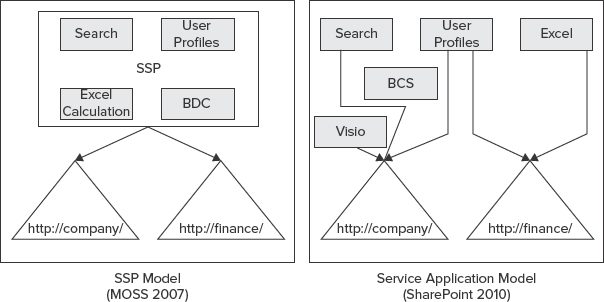
FIGURE 9-1: New service application model in SharePoint 2010
With that cleared up, let's now take a look at what this new model has to offer, and the rationale behind bringing about such a fundamental change in the platform.
Hello Service Applications
The idea with the new service model in SharePoint 2010 is simple. If you don't need a particular service application, you don't deploy it to your farm — period! Additionally, you can deploy multiple instances of the services. In fact, you can create as many instances of a given service application as you like.
The second layer of granular configuration with the new service model comes at the web application level. Unlike the lockdown model in SSP, in SharePoint 2010, web applications can pick and choose which service applications they want to consume, and in which combination.
Once you have an instance of a service application deployed to your farm, it can be shared across multiple web applications in the same farm, or even across different farms. Regardless of the sharing model, you can always modify the association between a web application and service applications at a later time.
Service applications can be deployed to different application pools to support process isolation. You can pick and choose which service applications should be within the same process, or within separate processes.
![]() One possible reason to think about process isolation from performance or security perspectives is when sharing service data across multiple applications.
One possible reason to think about process isolation from performance or security perspectives is when sharing service data across multiple applications.
Figure 9-2 shows how various services are distributed in two application pools.
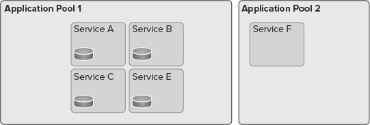
FIGURE 9-2: Distribution of services in two application pools
Although in most implementations, the performance of your farm is best optimized if services exist in one application pool, in some scenarios the highest physical isolation of services is required. Thankfully, the new service application model enables you to create separate instances of service applications, and place them in different application pools.
Another difference between SSP and service applications is a better scalability model. You can select on which servers in the farm a particular service application service will be running by using the “Services on Server” page in Central Administration.
It's worth mentioning that a Search service application is a bit different in terms of how its topology is defined. The Search service application has several underlying components that can run on different servers, which, in turn, offers an extra layer of scale. Figure 9-3 shows the topology page of the Search service application where you can manage its different components, and on which servers those components operate.
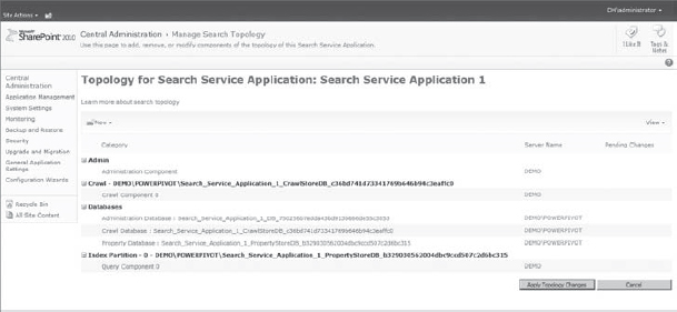
FIGURE 9-3: Topology page of Search service application
To wrap this up, following are the advantages of service applications over SSP:
- Granular configuration and control
- Scalable architecture
- Robust logical architecture
- Flexible sharing and deployment model
Available Service Applications by SharePoint Editions
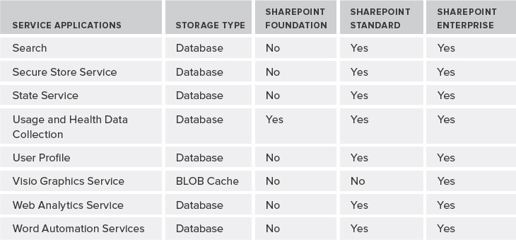
As an architect, it's imperative to know the architectural trade-offs and the service applications each edition of SharePoint offers. Table 9-1 provides quick rundown of all the service applications that ship out-of-the-box with different editions of SharePoint 2010, excluding service applications provided by other Microsoft products such Project Server, PowerPivot service, and so on.
TABLE 9-1: Service Applications Available by SharePoint Editions

Following are descriptions of each service application:
- Access Services — This service application allows for viewing, editing, and interacting with Access databases in a browser.
- Business Data Connectivity Service — The Business Data Connectivity Service (BCS) allows you to upload BDC models that define interfaces of other enterprise line-of-business (LOB) systems, and enables connectivity to those systems. The Application Registry service application is another service application that is a backward-compatible service to support the BDC API from SharePoint 2007.
- Excel Services — This service application allows viewing and interacting with Excel files from within the browser.
- Managed Metadata Service — This service application allows you to manage taxonomy hierarchies, keywords, and social tagging features of SharePoint 2010. This service application also handles content-type publishing across site collections.
- PerformancePoint — This service application supports configuration and monitoring of PerformancePoint as a business intelligence (BI) product integrated with the Enterprise edition of SharePoint 2010.
- Search — As its name implies, this service application (which comes with its own topology management configuration) is used to index content, and serves search queries performed by users or custom code.
- Secure Store Service — This is a credential mapping service to access other enterprise-level service applications or back-end enterprise systems.
- State Service — The State Service is a temporary storage of any data that deals with a user session.
- Usage and Health Data Collection — This service application provides storage usage and health information at the farm level, and provides various reporting functionalities on such data.
- User Profile — As yet another social feature in SharePoint 2010, this service application supports features such as My Sites, My Links, Colleague tracker, profile pages, personal tags and notes, and other social features.
- Visio Graphics Service — This service application enables viewing, interacting, and refreshing of Visio diagrams within a browser.
- Web Analytics Service — This service application provides an overarching solution to collecting and reporting on various analytical metrics at the farm, web application, site collection, and site levels.
- Word Automation Services — This service application allows you to view and edit Word documents in a web browser. It can also be used for document conversions.
Now that you are familiar with service applications in different editions of SharePoint, let's discuss the life cycle of a service application.
SERVICE APPLICATIONS LIFE CYCLE
A typical life cycle for a service application consists of several stages. When you plan your service application, consider each stage of this cycle. For example, you should understand when you must use the Configuration Wizard to provision your service applications or use Windows PowerShell, and when you must create a custom proxy group for your service applications.
Figure 9-4 shows the stages in a life cycle for a service application.
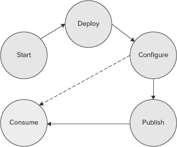
FIGURE 9-4: Life cycle for a service application
Starting Services
Although service applications are different from services, they still confuse many people working with SharePoint 2010.
If you browse to the “Services on Server” page in SharePoint Central Administration, that page lists all services that can be started and stopped on specific servers of the farm, as shown in Figure 9-5.

FIGURE 9-5: SharePoint “Services on Server” page in Central Administration
These services are mostly SharePoint wrappers around Windows services, and may or may not have an associated service application. For example, Central Administration is just a service that can be started on a server of the farm to turn it into a server that can host the Central Administration site — there is no service application associated with it.
As mentioned earlier in this chapter, a service application refers to a new deployment model for shared services. A service application represents a specific instance of a given service that can be configured and shared in a particular way. Service applications are comprised of Windows services, timer jobs, caching, SQL databases, and other stuff. They are just a broader concept than Windows services.
Deploying Service Applications
You can deploy service applications within a farm by using the following methods:
- Selecting the service applications in the Initial Configuration Wizard of your farm
- Adding new service applications or new instances of the existing service application in the Central Administration site
- Using Windows PowerShell
Table 9-2 describes the Windows PowerShell commands that you can use to manage service applications.
TABLE 9-2: Service Application Windows PowerShell Commands
| COMMAND | DESCRIPTION |
| Install-SPService | Installs the services in the farm. It runs once per farm. |
| Get-SPServiceInstance
Start-SPServiceInstance Stop-SPServiceInstance |
Operations related to managing the services instance for a specific server or the entire farm. |
| Get-SPServiceApplication
Publish-SPServiceApplication Remove-SPServiceApplication Set-SPServiceApplication Unpublish-SPServiceApplication |
Operations related to managing service applications deployed to a farm (such as sharing the specified local service application outside the farm). |
| Get-SPServiceApplicationProxy
Remove-SPServiceApplicationProxy Add-SPServiceApplicationProxyGroupMember |
Operations related to managing service application proxies. |
| Get-SPServiceApplicationPool
New-SPServiceApplicationPool Remove-SPServiceApplicationPool Set-SPServiceApplicationPool |
Operations related to managing the logical architecture of service applications. |
Regardless of your deployment approach, service applications can be isolated. To do so, during the provisioning process, you can either specify to use an existing application pool, or create a new application pool and have the service application run in its own worker process.
Configuring Service Applications
Once the service applications are configured at the farm level, they can all be managed in the Central Administration site. When you click “Manage service applications,” you are taken to the “Manage service applications” page, as shown in Figure 9-6.
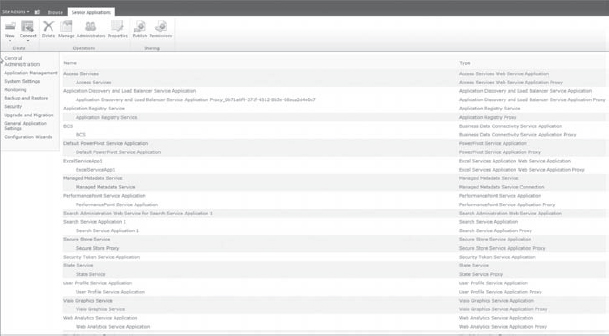
FIGURE 9-6: “Manage service applications” page
In the “Manage service applications” page, you should note three things:
- All deployed service applications are listed.
- All service application connections are listed. (Service application connections are discussed in more detail later in this chapter.)
- You can add new service applications by clicking the New button in the Ribbon.
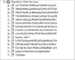
FIGURE 9-7: Identifier for service application
Once service applications are provisioned, if you open up the Internet Information Services (IIS) manager, you'll see that there is a web application called SharePoint Web Services, and underneath that web application are a bunch of virtual directories. Each of those virtual directories is seen by a globally unique identifier (GUID), or its identifier for the service application, as shown in Figure 9-7.
At a service database level, most of the service applications use their own set of databases.
![]() An important point to remember is that a service application may have one or more databases. For example, the User Profile service application has profile, synchronization, and social tagging databases. Another example is the Search service application with crawl, property, and administration databases. The number of databases can quickly add up, and be difficult to manage if you do not properly plan capacity.
An important point to remember is that a service application may have one or more databases. For example, the User Profile service application has profile, synchronization, and social tagging databases. Another example is the Search service application with crawl, property, and administration databases. The number of databases can quickly add up, and be difficult to manage if you do not properly plan capacity.
One issue with configuring service applications using the Configuration Wizard is that the associated virtual directory databases will end up having a lot of GUIDs. For example, the name for one of the User Profile databases could be User Profile Service Application_ProfileDB_899fd696a54a4cbe965dc8b30560dd07.
Though this might be acceptable in some cases, generally, a more intuitive naming convention makes a lot more sense. One way to resolve this issue is to use the “Manage service applications” page in the Central Administration site to add service applications individually, and then specify meaningful database names. The other alternative approach is to use Windows PowerShell to provision your service applications.
The following code snippet shows how you can provision a State Service service application using Windows PowerShell. Note how the SQL Server database and server name are specified in the code.
New-SPStateServiceDatabase -Name “StateServiceDatabase” -DatabaseServer
     “dhsqlsrv” | New-SPStateServiceApplication -Name “State Service Application”
     | New-SPStateServiceApplicationProxy -Name “State Service Application Proxy”
     -DefaultProxyGroup > $null
As mentioned previously, you can create and deploy your own service application. In that case, you can override the previous Windows PowerShell commands and add your own parameters.
Configuring Service Application Proxies
If you deploy your service applications using either the Configuration Wizard or via Central Administration, service application proxies are automatically created for you. If you use Windows PowerShell, then you must also manually create the proxy that goes along with that service application.
So, what's the service application proxy, anyway?
Essentially, the service application proxy is a virtual link that connects web applications to a particular service application. So, when you create your web application, you'll specify your association to a service application proxy, and it's the proxy that will actually manage the communication back and forth.
In addition to linking web applications to service applications, some proxies also include settings that can be modified independently from the service applications. For example, the proxy for the Managed Metadata Service application indicates whether or not the associated service application is the default storage location for corporate taxonomy store (such as keywords and column-specific term sets), as shown in Figure 9-8.
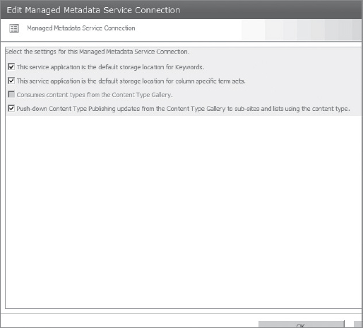
FIGURE 9-8: Managed Metadata Service application
![]() If there are multiple instances of the Managed Metadata Service application, (and, hence, multiple proxies), one of the instances must be specified as the primary, which hosts the corporate taxonomy store. All other instances are then secondary, providing additional data to the primary data. As an exception, the web parts that work with Managed Metadata Service applications work with data from all instances.
If there are multiple instances of the Managed Metadata Service application, (and, hence, multiple proxies), one of the instances must be specified as the primary, which hosts the corporate taxonomy store. All other instances are then secondary, providing additional data to the primary data. As an exception, the web parts that work with Managed Metadata Service applications work with data from all instances.
Configuring Proxy Groups
As its name implies, a service application proxy group is a grouping for service application proxies that are selected for a web application. A single service application proxy can be included in multiple proxy groups, or a proxy group may choose not to include a service application proxy based on the requirements of the target web applications.
When you set up your farm, by default, a default proxy group is created that includes all service application proxies. During the creation of a web application, you can select the default proxy group, or create a custom proxy group. Figure 9-9 shows a custom proxy group that includes only five of the existing service application proxies.
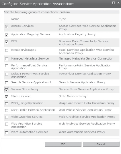
FIGURE 9-9: Custom proxy group
![]() A custom service application proxy group created for one web application cannot be associated with other web applications.
A custom service application proxy group created for one web application cannot be associated with other web applications.
From Windows PowerShell you can run the Get-SPServiceApplicationProxy cmdlet as shown in Figure 9-10, and that will list the service application proxy IDs. You can then use Remove-SPServiceApplicationProxy (which takes the ID as a parameter) and Add-SPServiceApplicationProxyGroupMember to remove a service application proxy, or to add a member to the service application proxy group.
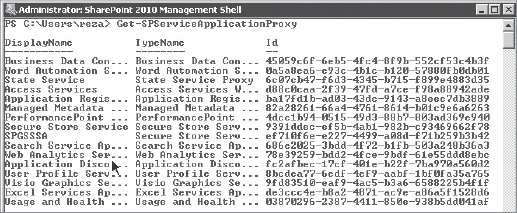
FIGURE 9-10: Service application proxy from Windows PowerShell
Consuming Service Applications
As mentioned previously, by default, all web applications in the local farm are associated with the default proxy group. This means that consuming the services in the local farm is not something that you must worry about, and it's automatically set up for you. If you ever decide to create a custom proxy group, you must decide how you want a specific web application to consume service applications.
To change the default proxy group for a web application, you must select Application Management in the Central Administration site, and click “Configure service application associations.” In the Service Application Association page, you'll see the default text under the “Application Proxy Group” heading. If you click it, you will be taken to a page where you can manage the members of that default proxy group. Additionally, if there were any custom proxy groups for each web application, they would be listed in the same page.
Again, it's worth mentioning that some connections might include settings that can be modified. For example, if a web application is connected to multiple instances of the Managed Metadata Service, you must indicate which service application hosts the corporate taxonomy.
Publishing Service Applications
A service application can be consumed with one or more web applications within the local farm, or it can be consumed by web applications in a remote farm.
Before going into more detail, let's clear up some terminology to ensure that you have a clear understanding:
- Publishing a service application — This means making a service application available for consumption across farms.
- Cross-farm service application — This is a service application that is made available to be consumed by remote farms.
At a high level, three things must happen to deploy service applications across farms:
- You must ensure that the farm that hosts the service application and the farm that needs to consume the service application have exchanged certificates to trust each other.
- You must publish the service application. To publish a service application, you must go to the “Manage service applications” page in Central Administration, and, from the Ribbon, click the Publish button. This will take you to the Publish Service Application page, where you specify a few settings, as shown in Figure 9-11.
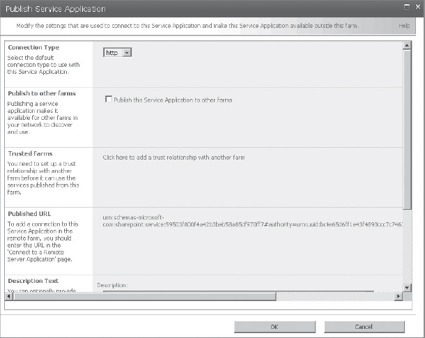
FIGURE 9-11: Publishing a service application
 One thing in Figure 9-11 that must be highlighted is the Published URL. This is the URL that will be used in the remote farm to locate the service application.
 - To consume a published service, go to the “Manage service applications” page in the remote farm and click the Connect button in the Ribbon. Next, choose which type of service you are connecting to, which, in turn, prompts you to enter the URL of the published service, as shown in Figure 9-12. Assuming that the trust has been already set up and properly working, just a service application proxy on the local farm is created to connect to the service application on the remote farm. Once the proxy is there, any web application in the local farm can consume the service application from the remote farm.

FIGURE 9-12: URL of the published service
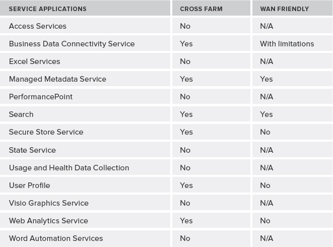
One thing that is important to note, however, is that not all service applications can be shared between farms. For example, BCS is a cross-farm service application, whereas other service applications are not designed to be shared between farms. Some cross-farm service applications are not recommended for use in wide area network (WAN) environments. Simply put, those cross-farm service applications that use Windows Communication Foundation (WCF) endpoints are; the ones that use ASMX web service are not.
Table 9-3 lists current recommendations for deploying service applications across farms or over a WAN.
TABLE 9-3: Recommendations for Deploying Service Applications
ARCHITECTURAL PRINCIPLES
SharePoint and its architecture have grown in evolutionary fashion over the years. While this process of evolution is one of the main reasons for the technology's success, it seems that one of the long-standing challenges in the SharePoint space is still an agreement on what “architecture” is specifically appropriate for a farm, or the applications that are built on the top of this technology. Do you need to start from modest beginnings and let it grow, or should you have a grand plan from the beginning?
As business goals and emphasis change, business requirements change. When the business requirements change, it has an impact on your overall architecture. So, the question is, how do you make your architecture future-proof? The answer is quite easy: you can't! However, with proper analysis and planning, and by following best practices, you can minimize the impact and narrow down possible flaws in your design in the future.
Well, service application architecture is no exception. This section provides general guidance for SharePoint architects working with SharePoint 2010. This section covers a few different implementations of service applications, and several common types of scenarios and technologies that you need to know upfront.
Architecture Examples
Although it's important to know what Microsoft recommends as possible implementations of service applications, keep in mind that each project has different requirements that should be considered carefully when you are doing your design.
With that being said, let's start with the simplest service application implementation, as shown in Figure 9-13. In this implementation, all service applications are deployed and consumed in a single local farm. They're all using the same application pool (no process isolation), and they're all part of the default proxy group. That means all web applications in the local farm are consuming all of the service applications that are available in this farm as well.
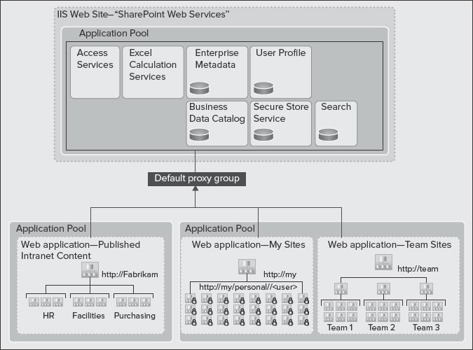
FIGURE 9-13: Implementation of a service application
If you require a simple architecture and most efficient use of farm resources to host a large number of sites, the architecture shown in Figure 9-13 is recommended.
Now, let's look at an architecture for multiple service applications, as shown in Figure 9-14. In this implementation, there are two proxy groups:
- Default proxy group — This is a subset of all of service applications, and it is associated with the Company Web and My Sites web applications.
- Custom proxy group — This is a particular web application (such as http://finance) that isn't associated with all of the service applications. It's using only a small subset of those. Hence, it's using a custom proxy group.

FIGURE 9-14: Implementation of multiple service applications
As you can see in Figure 9-14, service applications are logically isolated by placing them into two different application pools. Also, note that some of the service applications instances are shared between default and custom proxy groups, whereas some are dedicated to a particular web application.
![]() In this architecture, the Finance department is getting its own Excel Calculation Service and Access Services instances to optimize performance for a targeted group, and to isolate sensitive finance data.
In this architecture, the Finance department is getting its own Excel Calculation Service and Access Services instances to optimize performance for a targeted group, and to isolate sensitive finance data.
Obviously, the architecture shown in Figure 9-14 is more complex to configure, and requires far more resources to support multiple instances of some services. However, it's a flexible model that allows isolation of service data, and more granular configuration and control over service applications associated with different web applications.
Figure 9-15 shows an architecture where a farm (Farm A) is built to include a number of service applications to serve multiple farms across the enterprise. It offers centrally managed resources, and contains no web applications that serve content to end users. Hosted service applications are only meant to be consumed by other farms remotely.
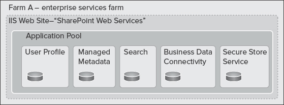
FIGURE 9-15: Enterprise services farm
This architecture is recommended when you want to optimize the resources within a farm for running services, rather than hosting content.
Now, take a look at the content-only farm in Farm B in Figure 9-16. This farm has two characteristics:
- No local service applications
- All service applications are consumed remotely from Farm A
Unlike Farm A, Farm B contains absolutely no service applications. It just contains web applications.
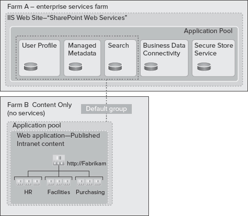
FIGURE 9-16: Farm A versus Farm B
From an implementation perspective, when configuring the web applications in Farm B, there will be a list of service application proxies, and they'll look exactly the same as if those service applications were installed in the local farm (that is, local to Farm B).
This configuration works well if you want to optimize the resources within your farm to host published content, rather than running service applications while consuming organization-wide data and other centrally managed resources from another farm.
Now, look at the combination of local service applications and remote service application consumption, an architecture known as hybrid, as shown in Figure 9-17.
In this architecture, there are two participating farms:
- Farm C — This farm contains a set of service applications locally for its own use. It's also consuming all enterprise service applications from Farm A remotely. The default proxy group contains proxies for the service applications from Farm A, as well as local proxies.
- Farm D — Just like farm C, this farm contains local and remote service applications, but it contains a deployment of services for a specialized department farm.
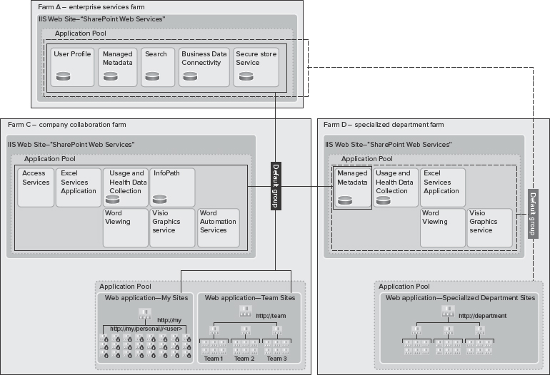
![]() Note a difference between Farm C and Farm D. Farm C consumes the Managed Metadata Service from Farm D. In this implementation, the department self-governs the taxonomy, and other social features of the Managed Metadata Service application, which is then shared with Farm C. Because this implementation contains two Managed Metadata Service applications, one must be designated as the primary, and the other one as secondary.
Note a difference between Farm C and Farm D. Farm C consumes the Managed Metadata Service from Farm D. In this implementation, the department self-governs the taxonomy, and other social features of the Managed Metadata Service application, which is then shared with Farm C. Because this implementation contains two Managed Metadata Service applications, one must be designated as the primary, and the other one as secondary.
The hybrid architecture is recommended if you must host multiple farms across your organization to meet your organizational business needs. This model also works well if you must optimize resources and administrative efforts based on each farm's characteristics and the roles they play in the overall enterprise architecture.
For example, a specialized department farm may not follow the same change-management life cycle that a farm containing a custom-built application follows. Obviously, in this case, process isolation absolutely makes sense. Another example is a published content-only farm that has different capacity and resource requirements from a department farm that comes with a ton of collaboration and less content.
If you decide not to use a dedicated enterprise services farm (Farm A), you can consider using cross-organization farms, as shown in Figure 9-18 and Figure 9-19.
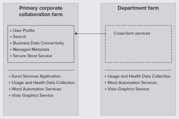
FIGURE 9-18: Cross-organization farms
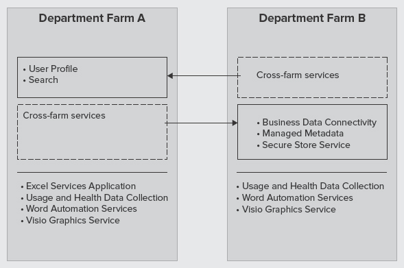
FIGURE 9-19: Cross-organization farms (Farms A and B)
In this architecture, try to share as many services as you can to avoid having a dedicated farm for services. For example, a department farm may choose to consume a subset of services from a primary corporate collaboration farm. Another example is when department Farm A and department Farm B exchange shared services to avoid duplication of services.
Inter-farm SSPs Versus Cross-farm Service Applications
The enterprise services implementation shown in the previous section is most analogous to the inter-farm shared services model in MOSS 2007. This model was used to enable web applications from one farm to use shared services from another farm using a parent/child model.
![]() Inter-farm and intra-farm shared services are not interchangeable terms. Intra-farm shared services mean that a MOSS 2007 farm uses the shared services of an SSP hosted within the farm.
Inter-farm and intra-farm shared services are not interchangeable terms. Intra-farm shared services mean that a MOSS 2007 farm uses the shared services of an SSP hosted within the farm.
There were three primary issues with inter-farm shared service, which have been addressed by cross-farm service applications:
- You could configure one SSP to provide shared services to all the other farms, and you could configure one SSP to consume all its services from a parent farm. However, you couldn't go both ways to publish and consume service applications from within a single farm.
- Child farms could use services only from one parent SSP.
- The child farm level also needed to have access to the parent farm databases, which could be a potential security issue in some implementations.
- Inter-farm SSPs were not supported across a WAN.
With cross-farm service applications in SharePoint 2010, any farm can both publish and consume service applications from other farms. More importantly, remote farms don't need permissions to the parent farm databases. Also, each farm can consume services from more than a parent farm. For example, look at Figure 9-17 again. Note how Farm C was consuming services from both Farm A and Farm D. Also, web applications can also use both local service applications and remote service applications, which is another improvement over the inter-farm shared services model in MOSS 2007.
Multi-tenancy
In implementations where you have multiple clients, one of the first architectural decisions that you may need to make is whether the design should follow a multi-tenant architecture.
Multi-tenancy is a relatively new principle in software architecture that revolves around the concept of the Software as a Service (SaaS) business model. In this model, a single software instance serves multiple client organizations, each known as a tenant. Remember, the multi-tenant architecture is based on a single software instance.
Multi-instance Architecture
A multi-tenant architecture is often contrasted with the multi-instance architecture, where separate software instances (or hardware systems) are implemented to serve multiple client organizations. A typical example of a multi-instance architecture is a hosting model where an authority (person or company) packages software and sells it. The authority provides services and deals with resources, cost, and subscriptions.
Figure 9-20 shows the difference between multi-tenant and multi-instance architectures at a high level. A multi-tenant architecture represents a single logical instance of software shared by many clients. In contrast, a multi-instance architecture follows a separate, logical software instance for each client.
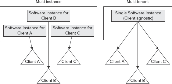
FIGURE 9-20: Difference between multi-tenant and multi-instance architecture
![]() Think of multi-instance architecture in SharePoint 2010 as the traditional model of deploying multiple farms (or a mega parent farm) and smaller child farms (inter-farm services), as explained earlier in this chapter.
Think of multi-instance architecture in SharePoint 2010 as the traditional model of deploying multiple farms (or a mega parent farm) and smaller child farms (inter-farm services), as explained earlier in this chapter.
It's important to note that the single-instance concept in a multi-tenant architecture does not mean that views of the application's data are shared between clients. For example, in Figure 9-20, Client B must not be able to see or modify Client A's application's data. However, whoever owns the application as a whole will have full access to all the data stored in the application for all clients.
Multi-tenant Architecture in SharePoint 2010
In SharePoint 2010, multi-tenancy is not as straightforward as what is demonstrated in Figure 9-20, because a SharePoint farm can be made up of multiple components, each of which should be considered separately in a multi-tenant architecture.
At a high level, multi-tenancy in SharePoint 2010 refers to a specific type of deployment that has the following two characteristics:
- It's on a shared set of resources within a single farm.
- It uniquely separates each tenant in the way they use the product's features (that is, it's on a per-tenant basis).
![]() Customers choose a multi-tenant architecture because it creates a true hosting environment, wherein server farm resources are maximized, and IT and licensing costs are dramatically reduced.
Customers choose a multi-tenant architecture because it creates a true hosting environment, wherein server farm resources are maximized, and IT and licensing costs are dramatically reduced.
Figure 9-21 shows a practical implementation of multi-tenancy in SharePoint 2010. This implementation has one web application with two tenants, each owning a few site collections within the same web application. The web application consumes service applications that are multi-tenant aware, and service data for each tenant is partitioned in the back-end database (that is, data isolation). Although both tenants are using the same service application, they have no visibility to the other tenant's data, because the service data is partitioned.
Two things about Figure 9-21 should be highlighted here.

FIGURE 9-21: Implementation of multi-tenancy in SharePoint 2010
First, not all service applications can be partitioned. That's because some services do not need to store tenant data, so they can be shared across multiple tenants without risk of exposing tenant-specific data. Table 9-4 lists the service applications that don't include the capability to be partitioned. A service application that cannot be partitioned is not a multi-tenant aware service application.
TABLE 9-4: Service Applications that Cannot be Partitioned
Second, this implementation uses one web application for all tenants. Although it's very common for tenants to have one or more site collections within the same web application, in a few scenarios each tenant may need its own web application, including the following:
- A tenant needs to deploy customizations that affect shared resources (such as the web.config file).
- A tenant requires a dedicated application pool (that is, process isolation) for performance or security reasons.
- All authenticated content for each tenant is hosted in one web application, while the other web application contains all publicly available content for each tenant.
If you decide to keep all your tenants in one web application using different site collections, several new or improved site collection features will be at your disposal:
- Additional support is provided for vanity domains using host header site collections (that is, multiple root-level site collections within a web application).
- Host header site collections support managed paths (for example, site collections http://foo.com and http://foo.com/sites/foo for tenant A and http://bar.comand http://bar.com/sites/bar for tenant B can co-exist in the same web application).
- Load balancer Single Sockets Layer (SSL) termination support is included.
- The Windows PowerShell cmdlet New-SPSite accepts a parameter that allows you to target a site collection to reside in a specific content database.
- Pluggable custom code (Site Creation Provider) allows you to enforce database organization across all your tenants. This is basically to ensure that, if a tenant creates a new site collection, that site collection ends up in the database you want, not just following the out-of-the-box round-robin algorithm.
- Sandboxed solutions allow each tenant to deploy custom code to their own site collection(s).
Although partitioned service applications and new features of site collections in SharePoint 2010 play an important role in the overall multi-tenant architecture, in reality, many more features enable multi-tenancy in SharePoint 2010. Following are some of these features:
- Microsoft SharePoint Foundation Subscription Settings Service adds multi-tenant functionality for service applications (available in all editions of SharePoint).
- Feature sets are groups of product Features that are enabled by farm administrators for tenants to activate and use.
- Site subscriptions are a logical group of site collections that can share settings, Features, and service data. Each site subscription has a subscription ID that is used to map Features, services, and sites to tenants, as well as partitioning their service data.
- Centralized and delegated administration allows the delegation of certain Central Administration tasks to tenant administrators using their own administration user interface, while the main Central Administration site is used to administer the entire SharePoint installation.
![]() Many of the multi-tenant features are deployed and managed using Windows PowerShell.
Many of the multi-tenant features are deployed and managed using Windows PowerShell.
Architecture Example
The new multi-tenant architecture in SharePoint 2010 provides more flexibility in the way you architect your services. You can mix multi-tenancy with previous architecture examples to come up with really optimal service application architectures.
For example, you can share some service data across the organization while other service data can be partitioned. Figure 9-22 shows a practical architecture where a combination of shared and partitioned service applications is employed.
In this architecture, all services are offered through the default group. However, three types of service applications exist:
- Service applications that are only shared in the local farm (such as Excel Calculation Services, Access Services, and so on).
- Service applications that can be shared cross-farm (such as User Profiles, Search, and BCS).
- Cross-farm service applications that can also support multi-tenancy. (For example, the Managed Metadata Service is shared cross-farm, which allows a central corporate taxonomy across the organization, while providing each tenant the capability to manage their own taxonomy. This removes the need for each tenant to have their own specialized farms.)
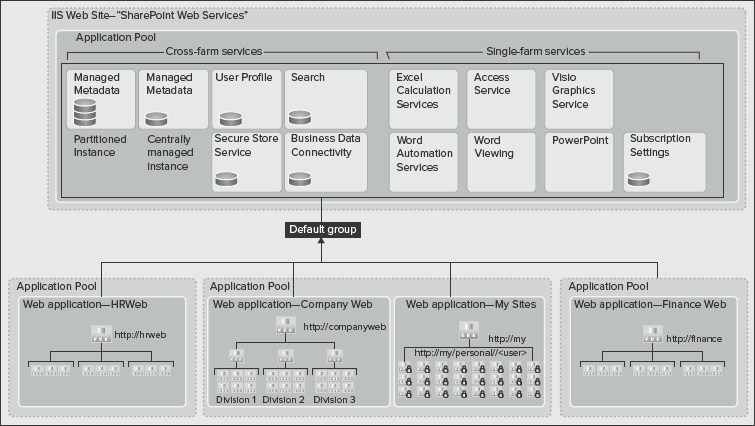
FIGURE 9-22: A combination of shared and partitioned service applications is employed
Load Balancing
SharePoint provides a basic load balancer that uses a round-robin algorithm to send requests to service applications. When a web application requests an endpoint for an associated service application (through proxy), the out-of-the-box load balancer returns the first available endpoint.
The underlying services of the service applications also use the out-of-the-box load balancer. If you click on the “Manage Services on server” page in Central Administration and go to the “Services on Server” page, you will see a list of all services in the current farm. On the top-right corner of the page is drop-down menu allowing you to switch to different machines in the farm, and choose to stop or start services on them. This means that more than one machine can run a particular service.
By default, a round-robin algorithm is used to load-balance SharePoint services, and you do not need to opt to use an external load balancer. Certain services (such as Excel Calculation Services) provide their own software load-balancing feature to ensure that no instance of a given service is overloaded at any time. Obviously, there might be some exceptions.
SUMMARY
Service applications in SharePoint 2010 are a powerful, scalable, and incredibly flexible architecture. They provide lots of new options for designing your farm in SharePoint 2010. Web applications can consume service applications a la carte. They can pick and choose which service applications in the farm or service applications being consumed remotely that they want to use within that particular web application.
Many design choices could be made based on usage, availability, process isolation, hardware, security, and so on. Service applications are really at the center of all SharePoint deployments.
Chapter 10 examines SharePoint 2010 platform architectures.