10
SharePoint 2010 Platform Architectures
By Bill Baer
A properly planned SharePoint topology is of primary importance to delivering a stable, scalable, available, and high-performing SharePoint environment. The process of planning a server farm environment includes many factors — including workload/scenario, business continuity management requirements, demand, and overall business requirements — both for today and in the future. Designing the right server farm environment for your scenario will go a long way toward ensuring that the environment meets the demands of your organization today, and will seamlessly scale in the future.
This chapter discusses the various components associated with a SharePoint 2010 Products topology, their characteristics, and how these components can be implemented to ensure meaningful deployment suitable for meeting existing and future demand.
SERVER FARM TOPOLOGIES
Server farms represent the topology that delivers SharePoint services to end users. A server farm is a collection of server machines acting together to provide a single solution or service.
SharePoint 2010 provides a high degree of flexibility when it comes to planning your topology. The core principle behind implementing a server farm is to enable elastic scale in the event the environment is required to support additional workloads, scenarios, or load. Server farms in SharePoint 2010 are implemented by establishing a base topology.
The core components of a server farm environment include the following:
- Front-end web servers with which users directly interact.
- One or more SQL Server database servers that store both configuration and content.
- Optional application servers that provide services tailored to your scenario (for example, servers that host the Search crawl and query components, or a dedicated server that hosts the SharePoint 2010 Central Administration website from where the server farm is centrally managed).
SharePoint 2010 can be deployed in a number of topology configurations. The basic topologies include small, medium, and large — otherwise known as single-tier, two-tier, and three-tier deployments — that define the placement and purpose of individual server machines that comprise the topology.
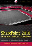
Each tier in a topology represents the purpose of the server machines hosted within it, or the services dedicated to those server machines. As shown in Figure 10-1 the three tiers in a SharePoint topology are classified as the Web, Application, and Database tiers.
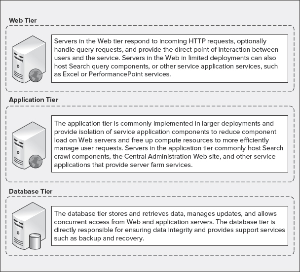
FIGURE 10-1: SharePoint 2010 tiers
Web Tier
The Web tier is comprised of web servers or other servers that receive and respond to HTTP requests. Web servers host SharePoint web applications in Internet Information Services (IIS). They can support additional services such as the Search query component sending requests to database servers in the Database tier, or communicating with application servers in Application tier to consume services hosted on those servers. Servers in the Web tier are exposed directly to end users, and should be secured behind a firewall or within a perimeter network.
Application Tier
The Application tier is an optional tier comprised of servers that are dedicated to the hosting of service applications associated with SharePoint 2010. Examples of servers in the Application tier include dedicated server machines that host the Search service, administration, and/or query components, in addition to services such as PerformancePoint or Excel Services.
The Application tier is most commonly associated with large server farm environments, where dedicated compute resources are required to support high search query volumes, large index corpuses, or to isolate service applications to free up resources on the Web tier to support high concurrency rates.
Database Tier
The Database tier is comprised of servers hosting SQL Server. Database servers in the Database tier respond to requests initiated by web and application servers, and update the underlying databases that support SharePoint 2010. The Database tier can be scaled both vertically (to improve performance) and horizontally (to improve performance and provide additional server farm resiliency).
![]() In Office SharePoint Server 2007, server machines were often referred to as server roles. In SharePoint Server 2010, roles are provided as components to provide the highest degree of flexibility, whereby a server's role is defined by which components are deployed to it. As a result, the terms “role” and “component” are interchangeable.
In Office SharePoint Server 2007, server machines were often referred to as server roles. In SharePoint Server 2010, roles are provided as components to provide the highest degree of flexibility, whereby a server's role is defined by which components are deployed to it. As a result, the terms “role” and “component” are interchangeable.
Small or Single-Tier Topology
A small or single-tier topology commonly consists of a single server deployment in which all components required to instantiate a SharePoint environment are installed on one machine including the database server — either through a dedicated SQL Server installation, or standalone installation using SQL Server Express edition.
Figure 10-2 shows an example of a single-tier topology, which is designed to support development or small businesses where scale and redundancy are not concerns.
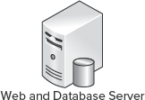
FIGURE 10-2: Single-tier topology
A single-tier topology does not provide any level of redundancy. Therefore, it requires an aggressive backup-and-restore strategy to be implemented, because this is the extent of data protection that can be provided in this deployment topology.
Because all components are installed on a single server, single-tier topologies are the least flexible, and do not support seamless scale. Scaling a single-tier topology requires backup of all content and components, as well as redeployment on a more flexible topology (at minimum, a medium or two-tier topology).
Medium or Two-Tier Topology
A medium or two-tier topology consists of two or more servers that support separation of SharePoint and SQL Server components. This includes one or more web servers installed with SharePoint 2010, and one or more database servers installed with SQL Server. Medium or two-tier topologies benefit from their flexibility in that they can seamlessly scale to meet the changing business needs or the demands of the organization.
Figure 10-3 shows a minimal two-tier topology comprised of one web server running SharePoint Server 2010 in the Web tier, and one database server running SQL Server 2005 or SQL Server 2008 in the Database tier.
Figure 10-4 shows a scaled two-tier topology that includes two load-balanced web servers running SharePoint Server 2010 in the Web tier, and two database servers running SQL Server 2005 or 2008 in the Database tier that can be clustered or mirrored to provide high availability and redundancy.
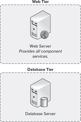
FIGURE 10-3: Two-tier topology

FIGURE 10-4: Two-tier highly available topology
The two-tier topology provides the most flexible deployment type, and is recommended for organizations of all sizes as a base topology. This topology can be both expanded and contracted through the introduction of additional server machines. As such, it is one of the most common deployments of a server farm, providing a flexible and scalable solution. A two-tier server farm enables an organization to seamlessly implement hardware or software load balancing such as Windows NT Load Balancing Service (WLBS) to distribute incoming HTTP requests evenly between web servers. This provides a means to handle an increase in demand as the number of requests submitted to it rise (for example, as the result of a merger or acquisition).
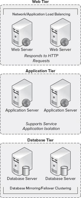
FIGURE 10-5: Three-tier topology
A two-tier server farm can also seamlessly scale at the Database tier through the introduction of additional database servers in a mirrored or clustered configuration. This provides additional resiliency and distribution of load within a server farm environment.
Large or Three-Tier Topology
A large or three-tier topology is designed for large organizations that require performance, scale, and adherence to strict business continuity management objectives.
Figure 10-5 shows a three-tier topology that consists of two or more web servers installed with SharePoint 2010, one or more application servers installed with SharePoint 2010, and two or more database servers installed with SQL Server.
The physical topology selected for SharePoint 2010 will drive the layout of the service application topology. In many cases, it may be easier to map the service application topology to a physical topology to help ensure that sufficient resources exist to support the overall deployment.
SERVICE APPLICATION TOPOLOGIES
In Office SharePoint Server 2007, services were contained within a Shared Services Provider (SSP). The SSP-provided services such as Search, personalization, business intelligence (BI), and portal usage reporting were self-contained within a separate web application. Although the SSP model provided a valuable function (in that resource-intensive services such as Search could be isolated within and shared across multiple web applications), deployment and flexibility were challenging, and did not provide third-party extensibility.
In SharePoint Server 2010, the SSP model has been retired in favor of a more flexible and á-la-carte consumption model provided through a new Shared Services architecture. In SharePoint Server 2010, services can be distributed as individual service applications, provisioned on demand at run time, or later in the deployment cycle, as business needs change and evolve.
Service applications provide the core capabilities to support the varying workloads in SharePoint 2010. They can be shared across farms, and accessed by users through the web applications hosting them. Service applications are associated with web applications through service application connections.
![]() Service application connections are also referred to as application proxies, and associate the service application with a web application through membership in a service application connection group, which is described later in this chapter.
Service application connections are also referred to as application proxies, and associate the service application with a web application through membership in a service application connection group, which is described later in this chapter.
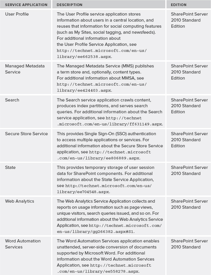
Table 10-1 lists the service applications that are available in SharePoint 2010.
TABLE 10-1: Service Applications in SharePoint 2010


Service applications are deployed through three primary entry points:
- Windows PowerShell
- Farm Configuration Wizard
- SharePoint 2010 Central Administration
![]() Some service applications can be deployed only through Windows PowerShell (such as the Subscription Settings Service Application). To learn more about deploying service applications, see http://technet.microsoft.com/en-us/library/ee704544.aspx.
Some service applications can be deployed only through Windows PowerShell (such as the Subscription Settings Service Application). To learn more about deploying service applications, see http://technet.microsoft.com/en-us/library/ee704544.aspx.
Service Application Groups and Associations
Service applications can be grouped and contained within a service application group, as shown in Figure 10-6. The service application group can be assigned to individual web applications, which allows you to expose only the necessary services needed to support the context of one or more web applications.
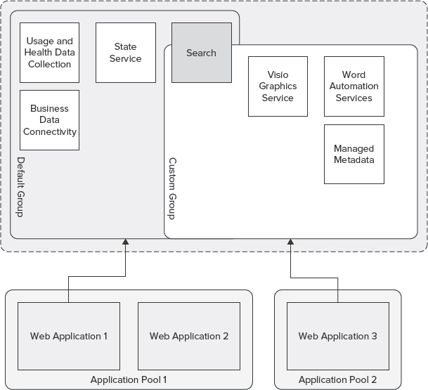
FIGURE 10-6: Service application groups
For example, a web application supporting finance operations within an organization may require PerformancePoint Services and Business Data Connectivity services, whereas a web application supporting document and records management may require the Managed Metadata Services (MMS). In this scenario, custom groups can be defined to support the unique requirements of each scenario, whereas the default group can be used to provide other essential services to facilitate collaboration and discovery (such as the Search services).
Figure 10-7 shows the Configure Service Application Associations dialog in SharePoint 2010 Central Administration.
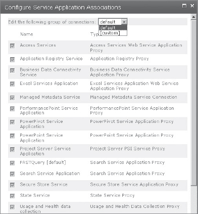
FIGURE 10-7: Configure Service Application Associations dialog
![]() Custom groups can be assigned only to web applications.
Custom groups can be assigned only to web applications.
Service Application Security
In environments where security is the primary factor in determining the appropriate topology, the flexibility provided through the service application architecture in SharePoint 2010 can be implemented to support those security requirements through concepts such as process isolation. Process isolation simply refers to protecting one process from other processes — for example, preventing Process 1 from writing into Process 2.
To utilize process isolation, a separate application pool is assigned to each service application to provide a process boundary. However, there is a tradeoff between security and performance, depending on the number of service applications and the extent of process isolation. Figure 10-8 shows service applications that are assigned to separate application pools.
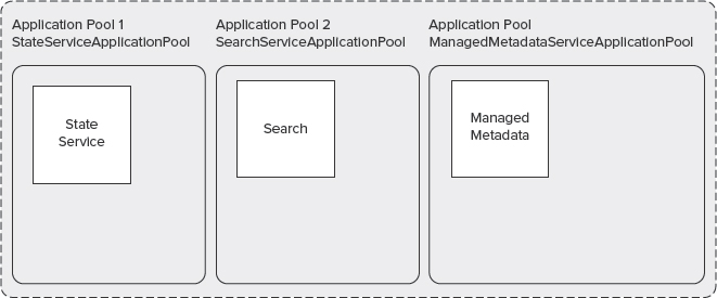
FIGURE 10-8: Process isolation
Multiple application pools should be used when you want to ensure that web applications are secure. For example, an organization can use multiple application pools to separate Human Resources and general open intranet collaboration websites hosted within the same environment, though separated through the assignment of unique application pools. By implementing multiple, dedicated application pools, you can prevent one organization from accessing, changing, or using confidential information from another organization's website.
Each web application within an application pool shares the same worker process, which operates as a separate instance of the worker process executable (w3wp.exe). Figure 10-9 shows the w3wp.exe file as displayed in Windows Task Manager.
Each separate worker process provides a process boundary. Therefore, when an application is assigned to an application pool, problems within it or another application pool do not affect one another. For example, if a worker process fails, it does not affect the applications running in other application pools.
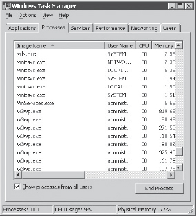
FIGURE 10-9: w3wp.exe in Windows Task Manager
When considering process isolation, you should carefully evaluate the impact on performance that multiple worker processes will have on the resources available to each server in the topology.
A number of methods for monitoring w3wp.exe resource utilization can be employed when evaluating the impact of multiple worker processes, or when attempting to diagnose issues related to worker processes.
Performance and Resource Monitor
Performance Monitor (shown in Figure 10-10) and Resource Monitor (shown in Figure 10-11) are utilities included in Windows Server that enable you to examine how programs you run affect your server's performance by collecting log data for later or real-time analysis. For example, to monitor worker processes, you can use the .NET CLR Exceptions performance object.

FIGURE 10-10: Performance Monitor
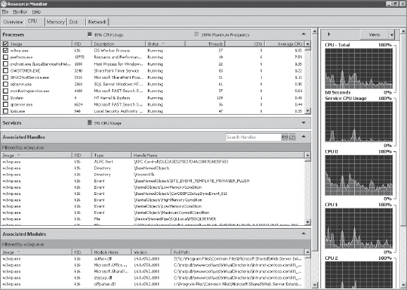
FIGURE 10-11: w3wp.exe in Resource Monitor
![]() Worker processes are exposed with a unique identifier represented as an incremental int, in order to surface the Process ID (PID) associated with a worker processes, as opposed to int. For more information, see http://support.microsoft.com/kb/281884.
Worker processes are exposed with a unique identifier represented as an incremental int, in order to surface the Process ID (PID) associated with a worker processes, as opposed to int. For more information, see http://support.microsoft.com/kb/281884.
Process Monitor
Process Monitor is a Sysinternals command-line utility that supports the monitoring of filesystem, registry, and process/thread activity. Using Process Monitor, you can surface the PID associated with a specific worker process, and subsequently narrow the monitoring scope to that PID.
![]() For additional information about Process Monitor, see http://technet.microsoft.com/en-us/sysinternals/bb896645.aspx.
For additional information about Process Monitor, see http://technet.microsoft.com/en-us/sysinternals/bb896645.aspx.
ProcDump
ProcDump is a Sysinternals command-line utility that supports the monitoring of worker processes for CPU spikes, in addition to facilitating the generation of crash dumps in the event a suspect worker process requires further evaluation to isolate problems.
![]() For additional information about ProcDump, see http://technet.microsoft.com/en-us/sysinternals/dd996900.aspx.
For additional information about ProcDump, see http://technet.microsoft.com/en-us/sysinternals/dd996900.aspx.
Planning Service Application Topologies
Planning the service application architecture should include the following considerations.
- Business requirements
- Federation scenarios
- Dedicated services scenario
Business requirements surrounding the deployment of service applications are commonly centered on the problem (or problems) the deployment of SharePoint Server 2010 is intended to solve — such as social networking within an organization, or rich search for quickly surfacing and working with information. Service applications should be carefully evaluated prior to deployment to ensure that they will facilitate meeting your organization's scenarios. Deploying those required service applications may help to satisfy business objectives.
Federated and dedicated services scenarios refer to whether service applications will be published to other deployments of SharePoint 2010, or provided through a dedicated services server farm. SharePoint 2010 refers to the federation of service applications as publishing. Publishing service applications enables a distributed organization to work together under a unified experience, and can reduce operational expenditures that accompany the maintenance and operations of multiple server farm environments.
Publishing service applications enables remote and secondary server farms to consume the services of a primary server farm environment. A dedicated services server farm, however, is designed to isolate services, and does not directly serve end-user requests.
Publishing Service Applications
Several service applications in SharePoint 2010 support federation (that is, they can be published and further consumed by another instance of SharePoint 2010). Figure 10-12 shows an example of an organization with a centralized deployment of SharePoint 2010 that supports the majority of end users, and a separate regional deployment that supports a satellite office. In this scenario, the Search service application can be published and consumed by the regional deployment, enabling a unified search experience, where the centralized deployment crawls the content of the regional deployment.

FIGURE 10-12: Published service applications
SharePoint 2010 supports publication of the following service applications:
- Business Data Connectivity
- Managed Metadata Service (MMS)
- User Profile
- Search
- Secure Store Service (SSS)
- Web Analytics
Publishing service applications requires that both the publishing and consuming farms are hosted within domains that share a trust — that is, the publishing farm domain must trust the domain of the consuming farm. To provide the broadest security boundary, one-way transitive (external) trusts can be established between the two domains.
Using external trusts provides access to resources that are located on a Windows NT 4.0 domain, or a domain that is located in a separate forest that is not joined by a forest trust, as shown in Figure 10-13.

![]() Domain trust relationships are required to support the Business Data Connectivity service application and the Secure Store Service application. The User Profile service application requires a two-way trust.
Domain trust relationships are required to support the Business Data Connectivity service application and the Secure Store Service application. The User Profile service application requires a two-way trust.
Once the infrastructure requirements have been met, publishing service applications requires exchanging trust certificates between the farms. These trust certificates include one root and one Security Token Service (STS) certificate. Exchanging trust certificates ensures that each farm acknowledges that the other farm can be trusted.
To exchange trust certificates between farms, the following steps are required:
- Export the root certificate from the consuming farm.
- Export the STS certificate from the consuming farm.
- Export the root certificate from the publishing farm.
- Import the root certificate and create a trusted root authority on the consuming farm.
- Import the root certificate and create a trusted root authority on the publishing farm.
- Import the STS certificate and create a trusted service token issuer on the publishing farm.
Let's take a look at each step in a bit more detail.
Step 1
To export the root certificate from the consuming farm, follow these steps:
- On the Start menu, click All Programs.
- Click Microsoft SharePoint 2010 Products.
- Click SharePoint 2010 Management Shell.
- At the command prompt (PS>), enter the following:
$certificate=(Get-SPCertificateAuthority) .RootCertificate
$certificate.Export(“Cert”) | Set-Content <drive>:<path>
     Root-Consuming.cer -Encoding byte
Replace the values for <drive>:<path> to represent your environment (for example, C:Temp).
Step 2
To export the STS certificate from the consuming farm, follow these steps:
- On the Start menu, click All Programs.
- Click Microsoft SharePoint 2010 Products.
- Click SharePoint 2010 Management Shell.
- At the command prompt (PS>), enter the following:
Replace the values for <drive>:<path> to represent your environment (for example, C:Temp).
Step 3
To export the root certificate from the publishing farm, follow these steps:
- On the Start menu, click All Programs.
- Click Microsoft SharePoint 2010 Products.
- Click SharePoint 2010 Management Shell.
- At the command prompt (PS>), enter the following:
$certificate=(Get-SPCertificateAuthority) .RootCertificate
$certificate.Export(“Cert”) | Set-Content <drive>:<path>
     Root-Publishing.cer -Encoding byte
Replace the values for <drive>:<path> to represent your environment, for example C:Temp.
![]() The STS certificate does not need to be exported on the publishing farm.
The STS certificate does not need to be exported on the publishing farm.
Once the appropriate certificates have been exported on both the publishing and consuming farms, they must be copied across each other, and subsequently imported and installed to establish the needed trust relationship.
Step 4
To import the root certificate and create a trusted root authority on the consuming farm, follow these steps:
- On the Start menu, click All Programs.
- Click Microsoft SharePoint 2010 Products.
- Click SharePoint 2010 Management Shell.
- At the command prompt (PS>), enter the following:
$certificate = Get-PfxCertificate <drive>:<path>Root-Publishing.cer
New-SPTrustedRootAuthority <Publishing Farm Identifier>
     -Certificate $certificate
Replace the values for <drive>:<path> to represent your environment, for example C:Temp.
![]() Trusted root authorities must be uniquely named. < Publishing Farm Identifier > should represent a unique name that represents the name of the consuming farm (for example, ContosoCentral).
Trusted root authorities must be uniquely named. < Publishing Farm Identifier > should represent a unique name that represents the name of the consuming farm (for example, ContosoCentral).
Step 5
To import the root certificate and create a trusted root authority on the publishing farm, follow these steps:
- On the Start menu, click All Programs.
- Click Microsoft SharePoint 2010 Products.
- Click SharePoint 2010 Management Shell.
- At the command prompt (PS>), enter the following:
$certificate = Get-PfxCertificate <drive>:< path>Root-Consuming.cer
New-SPTrustedRootAuthority <Consuming Farm Indentifier>
     -Certificate $certificate
Replace the values for <drive>:<path> to represent your environment, for example C:Temp.
![]() Trusted root authorities must be uniquely named. < Consuming Farm Identifier > should represent a unique name that represents the name of the consuming farm (for example, ContosoRegional).
Trusted root authorities must be uniquely named. < Consuming Farm Identifier > should represent a unique name that represents the name of the consuming farm (for example, ContosoRegional).
Step 6
To import the STS certificate and create a trusted service token issuer on the publishing farm, follow these steps:
- On the Start menu, click All Programs.
- Click Microsoft SharePoint 2010 Products.
- Click SharePoint 2010 Management Shell.
- At the command prompt (PS>), enter the following:
$certificate = Get-PfxCertificate <drive>:<path>STS-Consuming.cer
New-SPTrustedServiceTokenIssuer <Consuming Farm Identifier>
     -Certificate $certificate
Replace the values for <drive>:<path> to represent your environment, for example C:Temp.
![]() Trusted root authorities must be uniquely named. < Consuming Farm Identifier > should represent a unique name that represents the name of the consuming farm (for example, ContosoRegional).
Trusted root authorities must be uniquely named. < Consuming Farm Identifier > should represent a unique name that represents the name of the consuming farm (for example, ContosoRegional).
Completing the Process
When the required steps are completed to establish the publishing and consuming farm trust relationship, the selected service application can be published.
To set the permission to the application discovery and load-balancing service application on the consuming farm, follow these steps:
On the consuming farm:
- On the Start menu, click All Programs.
- Click Microsoft SharePoint 2010 Products.
- Click SharePoint 2010 Management Shell.
- At the command prompt (PS>), enter the following:
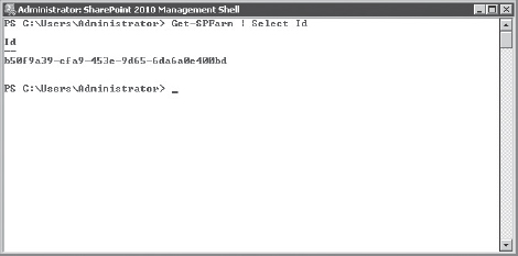
Get-SPFarm | Select Id
Note the consuming farm Id returned from the previous cmdlet, as shown in Figure 10-14.
On the publishing farm, follow these steps:
- On the Start menu, click All Programs.
- Click Microsoft SharePoint 2010 Products.
- Click SharePoint 2010 Management Shell.
- At the command prompt (PS>), enter the following:
$security=Get-SPTopologyServiceApplication | Get-SPServiceApplicationSecurity
$provider=(Get-SPClaimProvider System).ClaimProvider
$principal=New-SPClaimsPrincipal -ClaimType
     “http://schemas.microsoft.com/sharepoint/2009/08/claims/farmid”
     -ClaimProvider $provider -ClaimValue <Consuming Farm Id>
Grant-SPObjectSecurity -Identity $security -Principal $principal
     -Rights “Full Control”
Get-SPTopologyServiceApplication | Set-SPServiceApplicationSecurity
     -ObjectSecurity $security
Publishing a service application requires establishing permission to the Application Discovery and Load Balancing service application on the publishing farm for the consuming farm. This is a prerequisite to providing the consuming farm permission to the published service application.
Business Data Connectivity
To publish the Business Data Connectivity service application, complete the prerequisite steps outlined at the beginning of the “Publishing Service Applications” section earlier in this chapter.
On the publishing farm, follow these steps:
- On the Start menu, click All Programs.
- Click Microsoft SharePoint 2010 Products.
- Click SharePoint 2010 Management Shell.
- At the command prompt (PS>) enter:
$security=Get-SPServiceApplication <GUID>| Get-SPServiceApplicationSecurity
$provider=(Get-SPClaimProvider System).ClaimProvider
$principal=New-SPClaimsPrincipal -ClaimType
     “http://schemas.microsoft.com/sharepoint/2009/08/claims/farmid”
     -ClaimProvider $provider -ClaimValue <Consuming Farm Id>
Grant-SPObjectSecurity -Identity $security -Principal $principal
     -Rights <NamedAccessRights>
Set-SPServiceApplicationSecurity <GUID> -ObjectSecurity $security
Replace the values for <GUID>, <Consuming Farm Id>, and <NamedAccessRights> with the values returned from the previous steps. Optionally, to return the consuming farm Id, run Get-SPFarm | Select Id in the SharePoint 2010 Management Shell on the consuming farm to return its Id, and then run Get-SPServiceApplicationSecurity.<GUID>.NamedRights to return the name of the access rights on the publishing farm. To determine the Service Application GUID for the service application to be published, run Get-SPServiceApplication on the publishing farm, and locate the GUID associated with the service application to be published.
To publish a service application, on the publishing farm, follow these steps:
- On the Start menu, click All Programs.
- Click Microsoft SharePoint 2010 Products.
- Click SharePoint 2010 Management Shell.
- At the command prompt (PS>) enter:
Get-SPServiceApplication
Locate the desired service application and note the GUID associated with it, as shown in Figure 10-15.
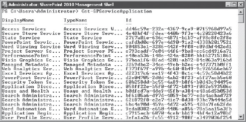
FIGURE 10-15: Service application GUID
At the command prompt (PS>), enter the following:
Publish-SPServiceApplication -Identity <Service Application GUID>
At the command prompt (PS>), enter the following:
Get-SPTopologyServiceApplication
Note the information returned from the previous cmdlet. This information will be used when configuring the consuming farm.
On the consuming farm, follow these steps:
- On the Start menu, click All Programs.
- Click Microsoft SharePoint 2010 Products.
- Click SharePoint 2010 Management Shell.
- At the command prompt (PS>), enter the following:
Receive-SPServiceApplicationConnectionInfo -FarmUrl
    <Publishing Farm Topology URL>
New-SPBusinessDataCatalogServiceApplicationProxy
     -Name “<Service Application Proxy Name>”
     -Url “<Publishing Farm Topology URL>”
Replace <Service Application Proxy Name> with a unique identifier that represents the service application that will be consumed (for example, Business Data Connectivity service application).
Replace <Publishing Farm Topology URL> with the information returned by the Get-SPTopologyServiceApplication cmdlet on the publishing farm.
Managed Metadata
To publish the MMS, complete the prerequisite steps outlined at the beginning of the “Publishing Service Applications” section earlier in this chapter.
On the publishing farm, follow these steps:
- On the Start menu, click All Programs.
- Click Microsoft SharePoint 2010 Products.
- Click SharePoint 2010 Management Shell.
- At the command prompt (PS>), enter the following:
$security=Get-SPServiceApplication <GUID>| Get-SPServiceApplicationSecurity
$provider=(Get-SPClaimProvider System).ClaimProvider
$principal=New-SPClaimsPrincipal
     -ClaimType “http://schemas.microsoft.com/sharepoint/2009/08/
     claims/farmid” -ClaimProvider $provider
     -ClaimValue <Consuming Farm Id>
Grant-SPObjectSecurity -Identity $security
     -Principal $principal -Rights <NamedAccessRights>
Set-SPServiceApplicationSecurity <GUID> -ObjectSecurity $security
Replace the values for <GUID>, <Consuming Farm Id >, and <NamedAccessRights> with the values returned from the previous steps. Optionally, to return the consuming farm Id, run Get-SPFarm | Select Id in the SharePoint 2010 Management Shell on the consuming farm to return its Id, and then run Get-SPServiceApplicationSecurity.<GUID>.NamedRights to return the name of the access rights on the publishing farm. To determine the service application GUID for the service application to be published, run Get-SPServiceApplication on the publishing farm, and locate the GUID associated with the service application to be published.
To publish a service application, on the publishing farm, follow these steps:
- On the Start menu, click All Programs.
- Click Microsoft SharePoint 2010 Products.
- Click SharePoint 2010 Management Shell.
- At the command prompt (PS>), enter the following:
Get-SPServiceApplication
Locate the desired service application and note the GUID associated with it, as shown earlier in Figure 10-15.
At the command prompt (PS>), enter the following:
Publish-SPServiceApplication -Identity <Service Application GUID>
At the command prompt (PS>), enter the following:
Get-SPTopologyServiceApplication
Note the information returned from the previous cmdlet. This information will be used when configuring the consuming farm, as shown earlier in Figure 10-14.
On the consuming farm, follow these steps:
- On the Start menu, click All Programs.
- Click Microsoft SharePoint 2010 Products.
- Click SharePoint 2010 Management Shell.
- At the command prompt (PS>), enter the following:
Receive-SPServiceApplicationConnectionInfo
     -FarmUrl <Publishing Farm Topology URL>
New-SPMetadataServiceApplicationProxy
     -Name “<Service Application Proxy Name>”
     -Url “<Publishing Farm Topology URL>”
Replace <Service Application Proxy Name> with a unique identifier that represents the service application that will be consumed (for example, Managed Metadata Service).
Replace <Publishing Farm Topology URL> with the information returned by the Get-SPTopologyServiceApplication cmdlet on the publishing farm.
User Profile Service
To publish the User Profile Service Application, complete the prerequisite steps outlined at the beginning of the “Publishing Service Applications” section earlier in this chapter.
On the publishing farm, follow these steps:
- On the Start menu, click All Programs.
- Click Microsoft SharePoint 2010 Products.
- Click SharePoint 2010 Management Shell.
- At the command prompt (PS>), enter the following:
$security=Get-SPServiceApplication <GUID>| Get-SPServiceApplicationSecurity
$provider=(Get-SPClaimProvider System).ClaimProvider
$principal=New-SPClaimsPrincipal
     -ClaimType “http://schemas.microsoft.com/sharepoint/2009/08/
     claims/farmid” -ClaimProvider $provider
     -ClaimValue <Consuming Farm Id>
Grant-SPObjectSecurity -Identity $security
     -Principal $principal -Rights <NamedAccessRights>
Set-SPServiceApplicationSecurity <GUID> -ObjectSecurity $security
Replace the values for <GUID>, <Consuming Farm Id>, and <NamedAccessRights> with the values returned from the previous steps. Optionally, to return the consuming farm Id, run Get-SPFarm | Select Id in the SharePoint 2010 Management Shell on the consuming farm to return its Id, and then run Get-SPServiceApplicationSecurity.<GUID>.NamedRights to return the name of the access rights on the publishing farm. To determine the service application GUID for the service application to be published, run Get-SPServiceApplication on the publishing farm and locate the GUID associated with the service application to be published.
To publish a service application, on the publishing farm, follow these steps:
- On the Start menu, click All Programs.
- Click Microsoft SharePoint 2010 Products.
- Click SharePoint 2010 Management Shell.
- At the command prompt (PS>), enter the following:
Get-SPServiceApplication
Locate the desired service application and note the GUID associated with it, as shown earlier in Figure 10-15.
At the command prompt (PS>), enter the following:
Publish-SPServiceApplication -Identity <Service Application GUID>
At the command prompt (PS>), enter the following:
Get-SPTopologyServiceApplication
Note the information returned from the previous cmdlet. This information will be used when configuring the consuming farm, as shown earlier in Figure 10-14.
On the consuming farm, follow these steps:
- On the Start menu, click All Programs.
- Click Microsoft SharePoint 2010 Products.
- Click SharePoint 2010 Management Shell.
- At the command prompt (PS>), enter the following:
Receive-SPServiceApplicationConnectionInfo
     -FarmUrl <Publishing Farm Topology URL>
New-SPUserProfileServiceApplicationProxy
     -Name “<Service Application Proxy Name>”
     -Url “<Publishing Farm Topology URL>”
Replace <Service Application Proxy Name> with a unique identifier that represents the service application that will be consumed (for example, Business Data Connectivity service application).
Replace <Publishing Farm Topology URL> with the information returned by the Get-SPTopologyServiceApplication cmdlet on the publishing farm.
Search
To publish the Search service application, complete the prerequisite steps outlined at the beginning of the “Publishing Service Applications” section earlier in this chapter.
On the publishing farm, follow these steps:
- On the Start menu, click All Programs.
- Click Microsoft SharePoint 2010 Products.
- Click SharePoint 2010 Management Shell.
- At the command prompt (PS>), enter the following:
$security=Get-SPServiceApplication <GUID>| Get-SPServiceApplicationSecurity
$provider=(Get-SPClaimProvider System).ClaimProvider
$principal=New-SPClaimsPrincipal
     -ClaimType “http://schemas.microsoft.com/sharepoint/2009/08/
     claims/farmid” -ClaimProvider $provider
     -ClaimValue <Consuming Farm Id>
Grant-SPObjectSecurity -Identity $security
     -Principal $principal -Rights <NamedAccessRights>
Set-SPServiceApplicationSecurity <GUID> -ObjectSecurity $security
Replace the values for <GUID>, <Consuming Farm Id>, and <NamedAccessRights> with the values returned from the previous steps. Optionally, to return the consuming farm Id, run Get-SPFarm | Select Id in the SharePoint 2010 Management Shell on the consuming farm to return its Id, and then run Get-SPServiceApplicationSecurity.<GUID>.NamedRights to return the name of the access rights on the publishing farm. To determine the service application GUID for the service application to be published, run Get-SPServiceApplication on the publishing farm, and locate the GUID associated with the service application to be published.
To publish a service application, on the publishing farm, follow these steps:
- On the Start menu, click All Programs.
- Click Microsoft SharePoint 2010 Products.
- Click SharePoint 2010 Management Shell.
- At the command prompt (PS>), enter the following:
Get-SPServiceApplication
Locate the desired service application and note the GUID associated with it, as shown earlier in Figure 10-15.
At the command prompt (PS>), enter the following:
Publish-SPServiceApplication -Identity <Service Application GUID>
At the command prompt (PS>), enter the following:
Get-SPTopologyServiceApplication
Note the information returned from the previous cmdlet. This information will be used when configuring the consuming farm, as shown earlier in Figure 10-14.
On the consuming farm, follow these steps:
- On the Start menu, click All Programs.
- Click Microsoft SharePoint 2010 Products.
- Click SharePoint 2010 Management Shell.
- At the command prompt (PS>), enter the following:
Receive-SPServiceApplicationConnectionInfo
     -FarmUrl <Publishing Farm Topology URL>
New-SPEnterpriseSearchServiceApplicationProxy
     -Name “<Service Application Proxy Name>”
     -Url “<Publishing Farm Topology URL>”
Replace <Service Application Proxy Name> with a unique identifier that represents the service application that will be consumed (for example, Search service application).
Replace <Publishing Farm Topology URL> with the information returned by the Get-SPTopologyServiceApplication cmdlet on the publishing farm.
Secure Store
To publish the Secure Store Service application, complete the prerequisite steps outlined at the beginning of the “Publishing Service Applications” section earlier in this chapter.
On the publishing farm, follow these steps:
- On the Start menu, click All Programs.
- Click Microsoft SharePoint 2010 Products.
- Click SharePoint 2010 Management Shell.
- At the command prompt (PS>), enter the following:
$security=Get-SPServiceApplication <GUID>| Get-SPServiceApplicationSecurity
$provider=(Get-SPClaimProvider System).ClaimProvider
$principal=New-SPClaimsPrincipal
     -ClaimType “http://schemas.microsoft.com/sharepoint/2009/08/
     claims/farmid” -ClaimProvider $provider
     -ClaimValue <Consuming Farm Id>
Grant-SPObjectSecurity -Identity $security
     -Principal $principal -Rights <NamedAccessRights>
Set-SPServiceApplicationSecurity <GUID> -ObjectSecurity $security
Replace the values for <GUID>, <Consuming Farm Id>, and <NamedAccessRights> with the values returned from the previous steps. Optionally, to return the consuming farm Id, run Get-SPFarm | Select Id in the SharePoint 2010 Management Shell on the consuming farm to return its Id, and then run Get-SPServiceApplicationSecurity.<GUID>.NamedRights to return the name of the access rights on the publishing farm. To determine the service application GUID for the service application to be published, run Get-SPServiceApplication on the publishing farm, and locate the GUID associated with the service application to be published.
To publish a service application, on the publishing farm, follow these steps:
- On the Start menu, click All Programs.
- Click Microsoft SharePoint 2010 Products.
- Click SharePoint 2010 Management Shell.
- At the command prompt (PS>), enter the following:
Get-SPServiceApplication
Locate the desired service application and note the GUID associated with it, as shown earlier in Figure 10-15.
At the command prompt (PS>), enter the following:
Publish-SPServiceApplication -Identity <Service Application GUID>
At the command prompt (PS>), enter the following:
Get-SPTopologyServiceApplication
Note the information returned from the previous cmdlet. This information will be used when configuring the consuming farm, as shown earlier in Figure 10-14.
On the consuming farm, follow these steps:
- On the Start menu, click All Programs.
- Click Microsoft SharePoint 2010 Products.
- Click SharePoint 2010 Management Shell.
- At the command prompt (PS>), enter the following:
Receive-SPServiceApplicationConnectionInfo
     -FarmUrl <Publishing Farm Topology URL>
New-SPSecureStoreServiceApplicationProxy
     -Name “<Service Application Proxy Name>”
     -Url “<Publishing Farm Topology URL>”
Replace <Service Application Proxy Name> with a unique identifier that represents the service application that will be consumed (for example, Secure Store Service application).
Replace <Publishing Farm Topology URL> with the information returned by the Get-SPTopologyServiceApplication cmdlet on the publishing farm.
Web Analytics
To publish the Web Analytics service application, complete the prerequisite steps outlined at the beginning of the “Publishing Service Applications” section earlier in this chapter.
On the publishing farm, follow these steps:
- On the Start menu, click All Programs.
- Click Microsoft SharePoint 2010 Products.
- Click SharePoint 2010 Management Shell.
- At the command prompt (PS>), enter the following:
$security=Get-SPServiceApplication <GUID>| Get-SPServiceApplicationSecurity
$provider=(Get-SPClaimProvider System).ClaimProvider
$principal=New-SPClaimsPrincipal
     -ClaimType “http://schemas.microsoft.com/sharepoint/2009/08/
     claims/farmid” -ClaimProvider $provider -ClaimValue <Consuming Farm Id>
Grant-SPObjectSecurity -Identity $security
     -Principal $principal -Rights <NamedAccessRights>
Set-SPServiceApplicationSecurity <GUID> -ObjectSecurity $security
Replace the values for <GUID>, <Consuming Farm Id>, and <NamedAccessRights> with the values returned from the previous steps. Optionally, to return the consuming farm Id, run Get-SPFarm | Select Id in the SharePoint 2010 Management Shell on the consuming farm to return its Id, and then run Get-SPServiceApplicationSecurity.<GUID>.NamedRights to return the name of the access rights on the publishing farm. To determine the service application GUID for the service application to be published run Get-SPServiceApplication on the publishing farm, and locate the GUID associated with the service application to be published.
To publish a service application, on the publishing farm, follow these steps:
- On the Start menu, click All Programs.
- Click Microsoft SharePoint 2010 Products.
- Click SharePoint 2010 Management Shell.
- At the command prompt (PS>), enter the following:
Get-SPServiceApplication
Locate the desired service application and note the GUID associated with it, as shown earlier in Figure 10-15.
At the command prompt (PS>), enter the following:
Publish-SPServiceApplication -Identity <Service Application GUID>
At the command prompt (PS>), enter the following:
Get-SPTopologyServiceApplication
Note the information returned from the previous cmdlet. This information will be used when configuring the consuming farm, as shown in Figure 10-14.
On the consuming farm, follow these steps:
- On the Start menu, click All Programs.
- Click Microsoft SharePoint 2010 Products.
- Click SharePoint 2010 Management Shell.
- At the command prompt (PS>), enter the following:
Receive-SPServiceApplicationConnectionInfo
     -FarmUrl <Publishing Farm Topology URL>
New-SPWebAnalyticsServiceApplicationProxy
     -Name “<Service Application Proxy Name>”
     -Url “<Publishing Farm Topology URL>”
Replace <Service Application Proxy Name> with a unique identifier that represents the service application that will be consumed, for example Web Analytics service application.
Replace <Publishing Farm Topology URL> with the information returned by the Get-SPTopologyServiceApplication cmdlet on the publishing farm.
Wide Area Networks
Some service applications in SharePoint 2010 can be published over wide area networks (WANs). This topology is useful when users are geographically distributed across multiple regions or localities.
For example, an organization may have a centralized data center with users from a corporate headquarters clustered around that data center. However, regional users comprise the manufacturing operations, and are distributed across the continent. To accommodate such a distribution, the organization could establish a primary intranet deployment in the primary data center, and extend or publish individual service applications over the WAN to support deployments in the regional locations.
In SharePoint 2010, service applications provide several improvements that enable support for latent links or limited throughput. These improvements include the following:
- Communication is over HTTP as opposed to direct database access (as in Office SharePoint Server 2007).
- Service applications are built on Windows Communications Foundation (WCF), which provides an optimized protocol that utilizes binary streams as opposed to XML.
SharePoint 2010 supports publishing the following service applications over WANs:
- Search
- MMS
- BBCS
Figure 10-16 shows a web application with a custom proxy group that is using both local service applications and consuming remote service applications from an enterprise services farm. It also shows two MMSs being consumed by a single web app. The MMS permits this, so you end up getting your corporate taxonomy from the enterprise services MMS, and it is merged (in the form of a union) with the MMS created just for this specialized web app.
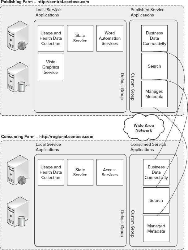
FIGURE 10-16: Service applications over WANs
Putting It All Together
Federation or publishing of service applications is beneficial in a number of deployment scenarios. For example, entire farms can be dedicated to service hosting, enabling centralized shared computing investments for very intense services such as Web Analytics or Search.
With SharePoint 2010, you can configure each web application to use service applications from different server farms. For example, you can share the Search service application across web applications in several server farms, while limiting PerformancePoint Services use to the local environment. This flexibility enables both the distribution of load through the isolation of compute-intensive applications, and improved end-user adoption. This enables the simplicity of providing only the services required to support the needs of the users.
SEARCH TOPOLOGIES
Deciding on the appropriate Search topology should take into consideration the same factors used when planning the server farm topology.
As shown in Figure 10-17, Search in Office SharePoint Server 2007 was provided through a single SSP. Its assets (that is, crawl history and metadata tables) were contained within a single database. Both query and index servers maintained a single copy of the flat-file index.

FIGURE 10-17: Office SharePoint Server 2007 Search architecture
Index servers could be associated with a single SSP, thus limiting scale, flexibility, and resiliency. Search in Office SharePoint Server 2007 was capable of scaling up to 50 million items, at which point the system was limited as a result of sharing the database across crawling and querying, and a single homogenous flat-file index. These constraints were exacerbated beyond 50 million items, and resulted in decreases in crawl performance, as well as query latencies and throughput.
As shown in Figure 10-18, SharePoint Server 2010 addresses these constraints and limitations by splitting the system into multiple, independently scalable components that include crawl components (indexer), crawl history and metadata databases, index partitions (query), and an administration component that includes an associated search administration database to store configuration information.

FIGURE 10-18: SharePoint Server 2010 Search architecture
The Search components in SharePoint Server 2010 are distributed across two primary elements, the query and crawl architectures, as shown in Figure 10-19.
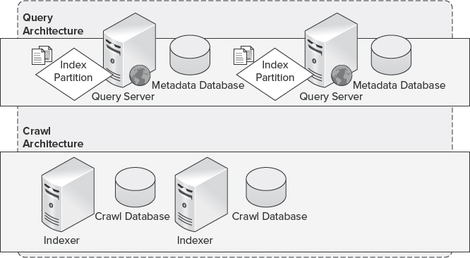
FIGURE 10-19: SharePoint Server 2010 Search architecture elements
Query Architecture
In SharePoint Server 2010 Search, the query architecture consists of query components, index partitions, and property or metadata databases.
- The query component returns search results to the query originator or end user. Each query component is part of an index partition, which is associated with a specific property database that contains metadata associated with a specific set of crawled content.
- An index partition represents a logical portion of the cumulative index, and is associated with the query component.
Figure 10-20 shows an example where the topology includes three index partitions and a single query component, with each query component hosting a third of the index. This scenario maximizes throughput by enabling parallelism when handling and responding to query requests submitted by end users.
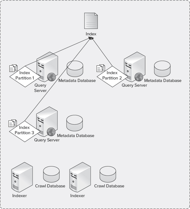
FIGURE 10-20: Index partitions
As shown in Figure 10-21, index partitions can be associated with one or more query components. Deploying multiple query components for a given index partition is useful where a high level of redundancy is required. The recommended initial Search topology should be instantiated with two query components configured for each index partition residing on separate server machines. This configuration will effectively provide a mirror of the index partition, and, in the event a server is lost or becomes inaccessible, the remaining server can continue to respond to queries submitted by end users.
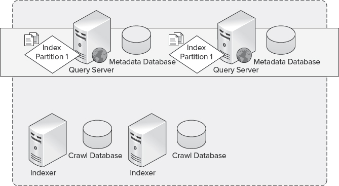
FIGURE 10-21: Mirrored index partitions
Crawl Architecture
In SharePoint Server 2010, the crawl architecture consists of crawl components, crawl databases, and property or metadata databases.
- The crawl component produces portions of the index (per index partition) and propagates them to the server machines hosting the query components associated with the specific index partition.
- The crawl database manages crawl operations and stores the crawl history. Each crawl database can be associated with multiple crawl components to provide redundancy where each crawl component crawls a separate portion of content during indexing.
- The property or metadata database stores properties of the crawled content. Scaling out the property database depends on the volume of content crawled (also known as the corpus) and the amount of metadata associated with each item in the scope of the crawl.
The flexibility afforded through Search in SharePoint Server 2010 enables you to address and mitigate system bottlenecks. For example, if you determine the SQL Server database is the bottleneck, you can add additional databases and scale out. Or, if the crawl process is the bottleneck, you can seamlessly add additional crawler machines to the topology.
To plan the appropriate scale-out topology for Search in SharePoint Server 2010, you should first understand component associations.
Keep in mind the following for crawl associations:
- Each crawl component is associated with only one crawl database.
- Each crawl database is associated with one or more crawl components.
Keep in mind the following for query associations:
- Each index partition is associated with only one metadata database.
- Each metadata database is associated with one or more index partitions.
The most common element to scale out is indexing. Indexing is the process that extracts both text and property information from files stored in content databases and/or on remote, networked hosts such as file shares. Indexing extracts the content by using filter components that understand a file's format (known as IFilters). Indexing then merges the extracted information into catalogs of indexes for efficient searches, combining both databases and flat-file indexes.
In short, indexing is the overall process of filtering, creating index entries, and merging them into catalogs to enable efficient lookup of information in a server farm. As a result, indexing can be a resource-intensive operation, depending on the size of the overall search corpus or content sources that are crawled.
You have two options when considering scaling out the indexing process:
- Separate the indexing process across machines
- Distribute crawler history across databases
In SharePoint Server 2010 Search, the appropriate topology is defined not only by performance and resiliency, but should also consider scale. In SharePoint Server 2010, each crawl component is capable of crawling or indexing up to 10 million items, at which point an additional crawl component should be instantiated in the topology, whether on the same machine hosting the initial crawl component where sufficient resources exist, or through instantiating a new crawl component on a new machine.
Figure 10-22 provides a planning base when considering the most appropriate Search topology, and describes each of the Search services component characteristics.
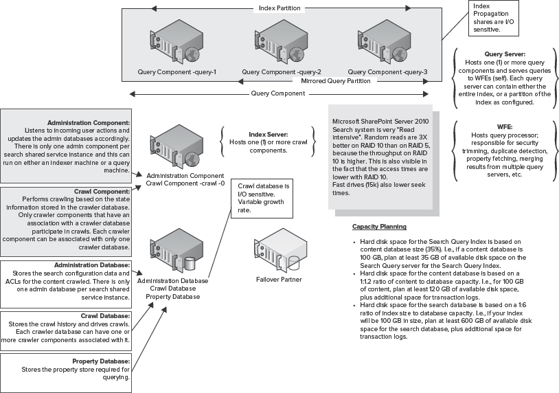
FIGURE 10-22: Search planning guide
When planning your Search architecture, it is important to understand both the impact of these components on server machine resources (where bottlenecks can occur) and what components bottlenecks are associated with. You should also consider the resiliency of both the physical and logical components associated with the SharePoint 2010 Search service.
GEOGRAPHICALLY DISTRIBUTED DEPLOYMENTS
Geographically distributed deployments refer to distributing SharePoint resources to support regional or global users. For example, an organization may have its headquarters in Seattle, Washington. However, many users may be distributed globally to support various corporate functions, or to respond to opportunities in specific geographic locations.
In this scenario, it can be costly to deploy a dedicated instance of SharePoint 2010 to support small pockets of users. Therefore, the organization may opt to introduce WAN optimization devices, whether symmetric or asymmetric, to accommodate latency or leverage technologies such as BranchCache in Windows Server 2008 R2.
In scenarios where the geographically dispersed user base is substantial enough to justify the cost of a localized, dedicated SharePoint 2010 deployment, an organization can opt to federate or publish service applications from the centralized server farm to the distributed server farms. This provides a unified experience to the remote user base. You could optionally isolate these server farms to support regulatory compliance related to those specific geographic locations.
SELECTING AN ARCHITECTURE
In many cases, selecting the appropriate architecture for your SharePoint 2010 deployment is the result of business and financial drivers. Selecting the appropriate architecture for SharePoint 2010 is the most important decision in topology planning, because the selected architecture will dictate its future capability to scale as demand grows. As documented previously in this chapter, a medium server farm provides the most flexible initial deployment topology that can be scaled both vertically and horizontally, and can seamlessly expand its scope to support both disaster recovery and high availability.
When considering your SharePoint 2010 architecture, it is important to consider extensibility, scalability, security, and how your architecture will map to those concerns and requirements. You should also consider how the logical architecture will be bound to the foundation provided through the physical architecture of your environment.
Consider not only how your design choices will impact capabilities, but also how well it will align to your business objectives. For example, what problems are you trying to solve with your deployment — reducing total cost of ownership, indexing large quantities of information, implementing high availability, or a combination of all of these objectives?
Once your objectives are clearly defined, you can move on to the next steps in the planning process, which include the following:
- Determining your administrative model
- Identifying costs
- Determining Service Level Agreements (SLAs) to include Recovery Point Objectives (RPOs) and Recovery Time Objectives (RTOs)
Determining an Administrative Model
Within its hierarchy, SharePoint 2010 provides management services at a number of levels, including the farm level, service application level, and site collection/site level.
The farm-level administrator manages the overall server farm environment through SharePoint 2010 Central Administration, or, optionally, through the SharePoint 2010 Management Shell using Windows PowerShell. More than one individual can be a farm administrator to manage the server farm through SharePoint 2010 Central Administration, or through the SharePoint 2010 Management Shell. Permissions for farm administrators can be assigned through SharePoint 2010 Central Administration, or through Local Users and Groups in the event the delegated administrator requires interactive logon access to machines that comprise the deployment.
New in SharePoint 2010 is the capability to delegate the administration of individual service applications by assigning permissions to individuals or groups of individuals to manage services (such as Search or the MMS). By delegating the administration of service applications, the service application administrator is able to perform all of the administrative tasks related to that service application. However, this administrator cannot manage other service applications or settings contained in Central Administration.
Site collection and site administrators manage the aspects of site collections and sites, such as creation of subsites, adding and removing users, and other administrative tasks associated with that scope.
Identifying Costs
When selecting a SharePoint 2010 architecture, is it important to ensure that the architecture will be within any cost boundaries or constraints that are associated with the service. These factors include the procurement of hardware and software necessary to deploy SharePoint 2010.
For example, you should determine whether existing hardware can be used or repurposed to support your deployment, or whether new hardware will be required — particularly where demand is expected to increase over time. Modeling software costs includes determining the cost of both server and client access licenses.
Determining Service Level Agreements
SLAs define agreements between the organization and service owners. SLAs can include communication protocols, performance requirements, and uptime guarantees (such as the availability expectations associated with the service). An aggressive availability expectation (such as the capability to support 99.99 percent availability) can require additional hardware in order to meet those expectations.
In short, a properly planned architecture will provide the flexibility to continuously scale or contract as business requirements dictate. Ensuring this flexibility should take many factors into account, such as those documented here, as well as unique requirements associated with your organization.
SCALING YOUR ARCHITECTURE
When selecting a topology, it is important to consider both your current and future needs to ensure that the environment provides the best possible flexibility to meet future demand, and offers both performance and high availability. SharePoint 2010 can be scaled both vertically and horizontally, depending on your individual needs. Assessing these needs is an important step in planning your scale strategy.
As demand or business requirements change over time, you must consider whether to scale up (vertically) or scale out (horizontally) to accommodate that demand or change in business requirements. The decision to scale up or scale out is commonly the result of performance monitoring used to identify physical bottlenecks and determine which resources are overused or nearing capacity. In some scenarios, these decisions may be based on whether redundant components are needed to provide high availability.
Factors Affecting Scaling
The most important factors influencing a scale-up or scale-out decision can be categorized as follows:
- Processor (compute)
- Memory
- Disk
Processor
Web and application servers are most commonly constrained by their processing capabilities because of factors that include a large number of worker processes, Secure Sockets Layer (SSL) encryption, and/or performance optimizations such as HTTP compression. Addressing processor bottlenecks most commonly requires scaling up by adding compute capacity through additional physical or logical processors.
Memory
Memory bottlenecks can occur across a server farm as the result of a large number of worker processes, query execution, or search indexing. In many cases, isolated increases in memory utilization can be addressed through increasing the physical memory associated with the constrained server machine. However, sustained high levels of memory utilization should be approached from a scale-out perspective, introducing additional server machines to share the load.
Disk
Disk bottlenecks are most often isolated to the Database tier. Disk bottlenecks can result in increased processing time, delaying the response to end users for such things as page requests. Disk bottlenecks are most commonly addressed by increasing the number of disks allocated to a Logical Unit Number (LUN), increasing the overall I/O available to that LUN, and the databases that reside on it. As a best practice, write optimized Redundant Array of Inexpensive Disks (RAID) sets (such as RAID 1+0 or RAID 0+1) to address the broadest range of I/O and provide the highest level of redundancy.
Deciding to Scale Up
When you scale up a topology, you employ a vertical scale, or, upgrade the hardware components within a server farm to address a specific bottleneck (such as processors, memory, and/or disk I/O). Scaling up defines the addressing of the resources assigned directly to one or more servers in the server farm (such as increasing available memory).
For example, a scale-up decision may be considered where it is determined insufficient memory exists on web and application servers to manage the running worker processes assigned to individual application pools. In this example, if you scale out the Web and/or Application tier using similar hardware, you will be constrained by the same challenges as worker processes associated with web applications, and service applications will be deployed to each node introduced in the topology.
Deciding to Scale Out
When you scale out a topology, you employ horizontal scale, which means the addition of compute units to support an increase in overall demand.
For example, an organization may elect to add web servers to a topology to increase performance, more efficiently distribute load, and, as a result, improve the user experience and performance of the server farm and its operations. Conversely, an organization may elect to add additional database servers to distribute load within a server farm between the Web and Application tiers, or to provide redundancy to support high availability within the server farm.
In a typical scale-out server deployment, multiple web servers share a single database server on a remote SQL Server instance. Figure 10-23 shows an example of a typical scale-out server deployment configuration with a remote SQL Server instance. Deploying SharePoint 2010 in a scale-out deployment provides a highly available and scalable topology.
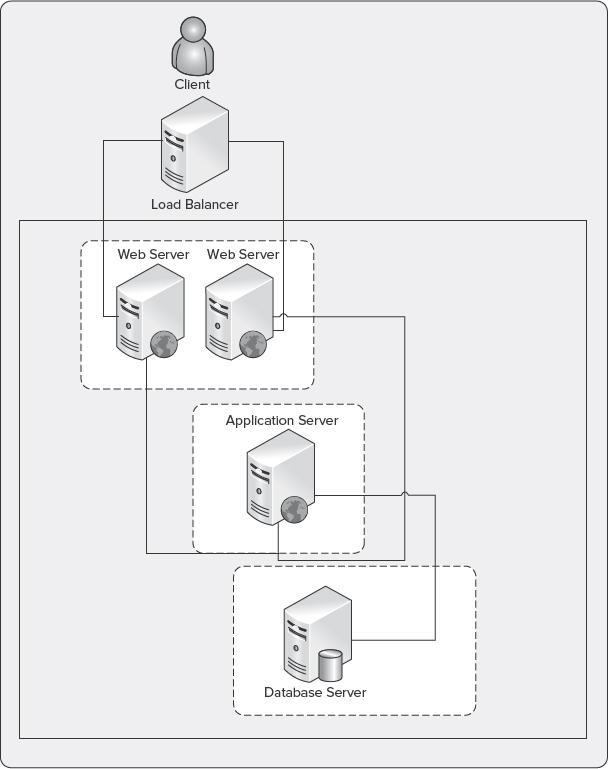
FIGURE 10-23: Typical scale-out deployment
A scale-out server deployment is recommended in the following circumstances and scenarios:
- High-collaboration environments where concurrent users or frequency of content updates is the measured value, resulting in decreased processing or rendering times
- High-availability scenarios where unplanned downtime is sought to be prevented
- To improve the performance of operations and service delivery to end users
Depending on the elected database server configuration in a scale-out deployment, you may be limited to specific versions of SQL Server and the hardware on which it operates — such as failover clustering, or optionally, for a higher degree of hardware flexibility, database mirroring may be considered.
Figure 10-24 shows an example of a scale-out server deployment configuration where SharePoint is deployed on an instance that is part of a failover cluster. By implementing a failover cluster, you can enhance the fault tolerance of SharePoint 2010.
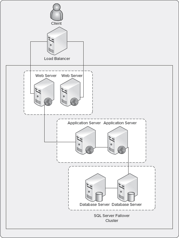
FIGURE 10-24: Scale-out server deployment with failover clustering
In addition to the typical scale-out deployment, it may become necessary to implement an advanced scale-out deployment to support additional performance and resiliency. For example, load-balancing servers can be used to distribute load more evenly and provide high availability within the Web and/or Application tiers. Figure 10-25 shows an example of an advanced scale-out server deployment.

FIGURE 10-25: Advanced scale-out server deployment
The advanced scale-out deployment benefits from many of the same advantages associated with standard scale-out deployments. However, this deployment is optimized for performance through the separation of load-balanced web servers to distribute user requests, multiple application servers to distribute service application services (such as Search processing), and clustered database servers in an Active Directory configuration to provide load distribution within the server farm.
In summary, the following conditions are most commonly considered when planning a scale-out deployment configuration:
- The web, application, and/or database server(s) become a bottleneck attributed to the following conditions:
- Compute resources are limited or are becoming over-extended, resulting in little to no headroom for growth.
- Memory and/or I/O capacity is limited or has reached peak utilization, and additional servers are the only possibility for providing more resources.
- The costs associated with scaling up (vertical) are barriers to addressing resourcing within the server farm. For example, high processor utilization can be addressed by increasing the available physical processors, which is often more costly both in procurement and operations than the inclusion of a separate server instance.
- Scale-up does not sufficiently address the bottlenecks within the server farm (such as those associated with I/O or memory-constrained systems).
Considering the Trade-offs
Trade-offs are associated with scale-up and scale-out topologies:
- Scale-out topologies introduce a large number of server machines, thus increasing the operational complexity related to day-to-day management (such as the application of public and cumulative updates, as well as Service Packs).
- Scale-up topologies will generally result in increased capital expenditures because additive hardware is typically more costly than the addition of server hardware. This requires careful planning both to accommodate the required downtime, and development of mitigation plans in the event problems occur as the existing hardware is scaled.
Considering Network Performance
Communication across a network is critical to the performance of both SharePoint 2010 and the clients interacting with it. Often overlooked is network performance. However, it should be considered in the same category as other bottlenecks (such as processors or disk). The performance of your network has an impact on the performance of operations executed by end users. When optimizing SharePoint 2010 performance, you should also consider analyzing network performance, including the monitoring of traffic and resource utilization.
SharePoint 2010 requires that each machine within a server farm environment respond to each other within 1 ms (round-trip time, or RTT) to ensure intra-farm communication is efficient. Also, the storage subsystem should return the first byte of a request (time to first byte, or TTFB) in 20 ms.
There are two primary utilities for monitoring network performance — System Monitor and Network Monitor.
System Monitor
System Monitor periodically captures snapshots of system performance characteristics and displays that information in a visual and structured way through graphs. These can help to quickly identify issues and develop an action plan for future resource requirements.
Using System Monitor, you can create a new Network Interface Data Collector Set to capture information about resource utilization, and to monitor resources for potential spikes in activity, thus enabling you to trace issues back to their origins.
![]() For additional information on how to create a log in System Monitor, see http://support.microsoft.com/kb/248345.
For additional information on how to create a log in System Monitor, see http://support.microsoft.com/kb/248345.
Network Monitor
Similar to System Monitor, Network Monitor can track network throughput as captured network traffic both locally and remotely (such as remote frames from other server machines on the network).
![]() To learn more about Network Monitor, see http://technet.microsoft.com/en-us/library/cc723623.aspx.
To learn more about Network Monitor, see http://technet.microsoft.com/en-us/library/cc723623.aspx.
Dealing with Network Bottlenecks
The most common network bottlenecks are related to overloaded servers or network components. Resolving network performance issues can be instrumented through several possible solutions, including the following:
- Using network cards with the highest available bandwidth
- Using adapters that support checksum offloading, IP Security (IPSEC) offloading, and large send offloading
- Placing different protocols on different adapters
- Using network adapters that support interrupt moderation
Considering Active Directory
Many SharePoint 2010 deployments continue to use Classic Mode, or Integrated Windows Authentication, which can increase the overall load on domain controllers because of the process through which clients are authenticated. When using Integrated Windows Authentication, the user is not initially prompted for credentials. This initial request is made anonymously, unless the current Windows user information can be used.
If the exchange fails, the user is prompted for credentials, which are processed using Integrated Windows Authentication. Users can be prompted up to three times for credentials, though, in the case where the user has logged on to the local computer as a domain user, then no authentication is required for computers on that domain.
Despite improvements in the management of authentication over time, it is important to weigh the impact of a SharePoint 2010 deployment on your domain controllers, particularly as business dynamics change through scenarios such as mergers and acquisitions, or making the service more broadly available to users (resulting in increased authentication load). Monitoring authentication is one method through which you can determine the impact on domain controllers — or, otherwise, following the guidance of one domain controller per every five web servers.
![]() For additional information on browser authentication see http://support.microsoft.com/default.aspx?scid=kb;EN-US;264921.
For additional information on browser authentication see http://support.microsoft.com/default.aspx?scid=kb;EN-US;264921.
When monitoring authentication load on domain controllers, there are many approaches that cannot be covered here to include compute resource monitoring. A primary instance where monitoring should be considered is on the NETLOGON service. The NETLOGON service is a Local Security Authority Subsystem Service (LSASS) process that runs on each domain controller in a forest, and is responsible for verifying NTLM logon requests, in addition to registering, authenticating, and locating domain controllers. When monitoring or troubleshooting authentication problems, the NETLOGON service log files can be extremely useful for isolating potential issues, or planning future scale.
![]() For additional information on enabling debug logging for the NETLOGON service, see http://support.microsoft.com/kb/109626 and http://support.microsoft.com/default.aspx?scid=kb;EN-US;906736.
For additional information on enabling debug logging for the NETLOGON service, see http://support.microsoft.com/kb/109626 and http://support.microsoft.com/default.aspx?scid=kb;EN-US;906736.
Local Security Authority Subsystem Service (LSASS)
The LSASS is a process responsible for enforcing the security policy on the system. LSASS verifies users logging on to a computer or server machine, manages password changes, and creates access tokens.
Monitoring the LSASS is an important step toward understanding the impact of increased authentication load on domain controllers. By using the Active Directory (AD) Data Collector Set in Performance Monitor on each domain controller, you can compile reports using performance counters and tracing to provide insight into potential problems that should be evaluated when troubleshooting issues related to authentication.
To use the AD Data Collector Set, open Server Manager on one or more domain controllers, and expand the Diagnostics node. Under the Diagnostics node, select Reliability and Performance ![]() Data Collector Sets
Data Collector Sets ![]() System. Right-click Active Directory Diagnostics, and select Start from the list of available options.
System. Right-click Active Directory Diagnostics, and select Start from the list of available options.
Data collection will initiate and gather data for 5 minutes prior to compiling the report. Once the report is available, you should focus on issues where LSASS is causing high CPU utilization, in addition to looking at the specific Lightweight Directory Access Protocol (LDAP) queries that may be impacting server performance.
Domain controllers are often most affected by remote queries from computers in the environment. Using the network information in the report will help determine which remote clients are communicating most with the domain controller. In many cases, operations such as an AD import will result in application and/or web servers appearing in this section of the report. If a domain controller is found to be compute-starved and the problem cannot be attributed to problems on that server machine, consider adding additional domain controllers to accommodate the load.
ADTest.exe
When planning your SharePoint 2010 deployment, you may elect to proactively determine the load that could be generated as a result of authentication. ADTest.exe is a load-generation tool you can use that simulates client transactions on a host server to assess the performance of the domain controllers.
![]() To learn more about ADTest.exe, see www.microsoft.com/downloads/en/details.aspx?displaylang=en&FamilyID=4814fe3f-92ce-4871-b8a4-99f98b3f4338.
To learn more about ADTest.exe, see www.microsoft.com/downloads/en/details.aspx?displaylang=en&FamilyID=4814fe3f-92ce-4871-b8a4-99f98b3f4338.
Using Service Farms
Service farms are intended to isolate service applications that would otherwise limit the scale and performance of environments where users are actively using the service (SharePoint 2010). Implementing service farms to isolate service applications enables the scale-out of server farms and scale-up of components to meet the demand and optimize performance of specific service applications.
For example, consider an organization that requires the indexing of a large search corpus and expects a high volume of user transactions to be related to search queries. The organization may consider deploying the Search service application to dedicated hardware components that comprise an isolated server farm. This enables the resources within the server farm where users actively collaborate to be optimized for that specific scenario, while providing the capability to leverage the services provided through the service farm.
Service farms are generally implemented when a specific service is expected to impact the resources available to the primary server farm, or when providing services to multiple server farm environments within an organization.
Figure 10-26 shows two server farms, with a services farm optimized for Search, and a second server farm that hosts any other service applications supported for that server farm's scenario or characteristics.
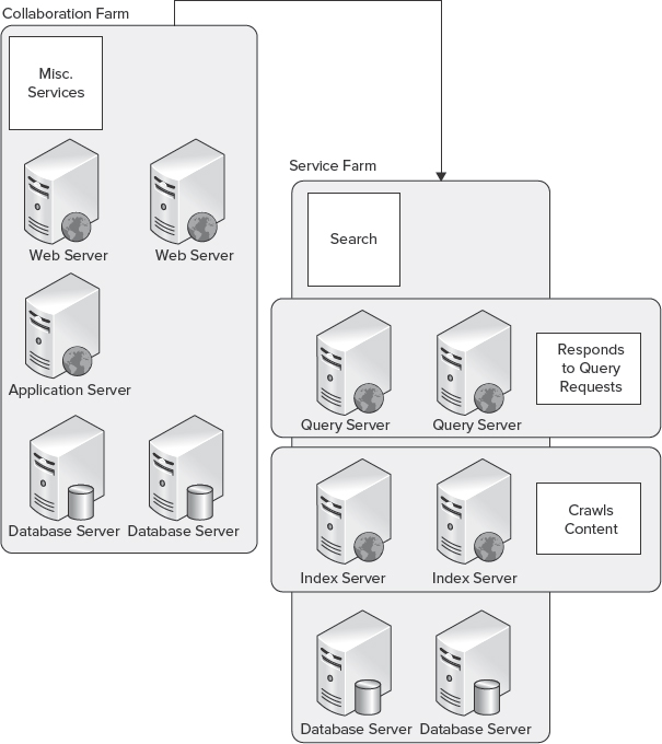
FIGURE 10-26: Server farms for Search and service applications
SUMMARY
Selecting the appropriate topology is essential to ensuring the delivery of a scalable deployment that meets both the current and future performance of your organization, as well as redundancy requirements. Topology planning should consider the business requirements today, and the potential needs of the future to ensure the deployment can scale seamlessly and evolve to support ever-changing business needs and scenarios.
This chapter provided the basic concepts and information to help you start thinking about these requirements, as well as the various levels of flexibility provided in SharePoint 2010. However, this chapter has not provided all the information required to plan and deliver the topologies needed for a variety of unique enterprise considerations.
Chapter 11 discusses how to work with internal and external data in SharePoint 2010.