Chapter 6: Exploring Common OpenSCAD Libraries
Reusing code written by others is an excellent way to speed up our CAD design process. With OpenSCAD, there are numerous libraries of code that we can utilize to create new and exciting designs. In this chapter, we will create a desk drawer using the BOSL Standard Library. Afterward, we will re-use the code we wrote to create our own OpenSCAD library.
In this chapter, we will cover the following:
- Exploring the OpenSCAD General libraries
- Exploring the OpenSCAD Single Topic libraries
- Creating our own OpenSCAD library
Technical requirements
The following is required to complete this chapter:
- Any late-model Windows, macOS, or Linux computer that can install OpenSCAD.
- The code and images for this chapter can be found here: https://github.com/PacktPublishing/Simplifying-3D-Printing-with-OpenSCAD/tree/main/Chapter6.
Exploring the OpenSCAD General libraries
The General libraries in OpenSCAD includes the BOSL, dotSCAD, NopSCADlib, and BOLTS libraries. Implementing these libraries allows us to add things such as threaded rods, modeled parts (parts that are not 3D-printed but are used in designs), and mathematically complex shapes. The following section includes a short breakdown of each of these libraries.
BOSL
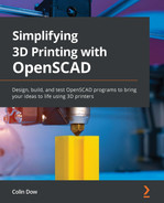
The Belfry OpenSCAD Library (BOSL) consists of operations to create shapes such as rounded boxes and threaded rods. Operations to enhance OpenSCAD's translate and rotate operations are also included in the BOSL.
In Figure 6.1, we can see a threaded rod created using the BOSL:
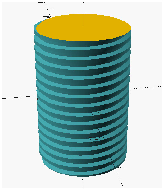
Figure 6.1 – A threaded rod created with the BOSL
We will be exploring the BOSL in more detail in the upcoming Using the BOSL to design a desk drawer section.
dotSCAD
The dotSCAD library aims to reduce mathematical complexity when using OpenSCAD. We can utilize dotSCAD to create complex shapes for our designs. In Figure 6.2, we can see a rose created in OpenSCAD using the dotSCAD library:
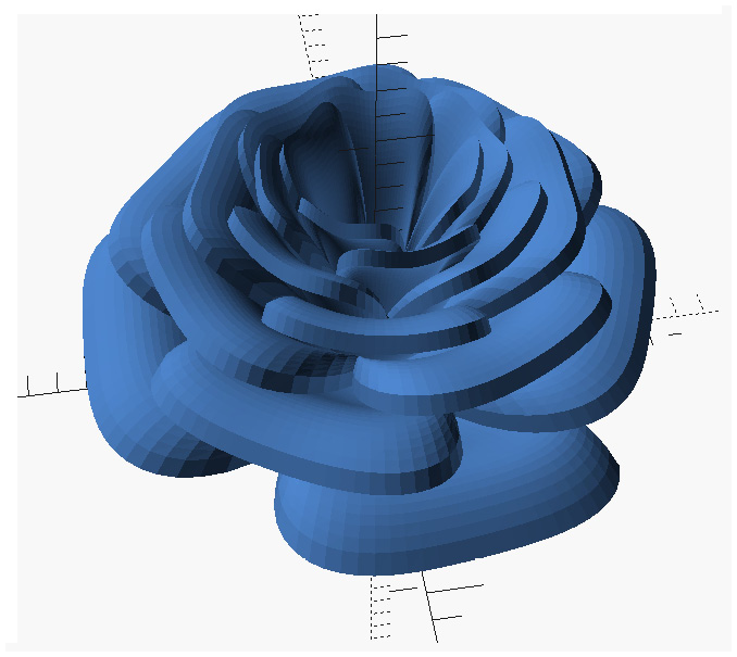
Figure 6.2 – An OpenSCAD rose using the dotSCAD library
This rose can be modified and easily put into our designs, saving us the hassle of importing a rose as a 3D object.
NopSCADlib
The NopSCADlib library provides modeled parts for use in our OpenSCAD designs. These parts include things such as bearings, batteries, and parts for RepRap 3D printers that cannot be 3D-printed.
In Figure 6.3, we can see a hygrometer rendered in OpenSCAD using the NopSCADlib library:

Figure 6.3 – A hygrometer from the NopSCADlib library rendered in OpenSCAD
This object was rendered using a single line of code and represents the standard mini hygrometer that can be purchased online at places such as Amazon and eBay.
Hygrometers and 3D Printing
Hygrometers measure ambient temperature and relative humidity and are useful tools for 3D printing. For hygroscopic filaments, such as nylon, it is important to keep the environment as dry as possible when storing and printing. Hygrometers placed with filaments in vacuum bags or in 3D printer enclosures allow us to measure the relative humidity and adjust the environment (such as the addition of silica packets).
Rendering non-3D-printable objects in OpenSCAD allows us to design around objects such as hygrometers. This saves us from having to measure the part in the real world and compensate for it in our OpenSCAD design.
BOLTS
BOLTS (not an acronym) is a free and open source library of standard parts that we can incorporate into our OpenSCAD designs. These parts consist mainly of standard nuts, bolts, pipes, and so on that we can use with our 3D-printed parts in our projects.
In Figure 6.4, we can see a pipe generated using the BOLTS library. Three parameters were used to create this pipe – the inside diameter (8 mm), the outside diameter (10 mm), and the length of the pipe (50 mm). The part was generated with the pipe(10, 8, 50) command:

Figure 6.4 – A pipe generated with the BOLTS library in OpenSCAD
Now that we have looked briefly at the OpenSCAD standard libraries, let's create a design using what we have learned. We will design a desk drawer by utilizing the BOSL. To create this design, we will download and install the library onto our computer. We will then use modules from the BOSL to create our desk drawer – a drawer with rails that rides on sliders bolted to the underside of a desk.
Let's get started.
Using the BOSL to design a desk drawer
As mentioned in the previous section, there are shapes such as rounded boxes that we can create using the BOSL. We will design our desk drawer using these shapes from the BOSL.
We will start by downloading and installing the library.
Downloading and installing the BOSL
To download the BOSL, we do so from the OpenSCAD website. We then unzip, rename, and copy the contents into our OpenSCAD libraries folder.
To do so, follow these steps:
- Navigate to the OpenSCAD libraries web page using the following URL: http://www.openscad.org/libraries.html.
- Click on the Library link under BOSL. This will take us to the GitHub page for the BOSL.
- Click on the green Code drop-down button and select Download ZIP.
- Download and unzip the file. Observe that there is a folder called BOSL-master. Open this folder.
- Observe that there is a folder with the same name (BOSL-master) inside. Rename this folder BOSL.
- In OpenSCAD, click on File | Show Library Folder.... Observe that the libraries folder opens.
- Copy the BOSL folder to the libraries folder.
We have now installed the BOSL into our OpenSCAD installation. Let's start our design by creating the tray portion with a BOSL rounded box.
Creating the drawer tray
Before we create our design, we must import the libraries we require and set any variables we will use. To create the drawer tray of our desk drawer, we will start with a rounded box from the shapes.scad BOSL file:
- In a new OpenSCAD file, add the following line to the top of the file:
use <BOSL/shapes.scad>
Observe that we do not need to put a semicolon at the end of the use line.
- We will now set the variables for our design. Add the following after the first line:
$fn=200;
width = 190;
length = 190;
height = 70;
rail_size=10;
hollow_factor = 0.95;
We already know that $fn sets the resolution of the design. The rest of the variables will be used to create the objects that will form our design.
- Next, add the following line below the variables, which will generate a cuboid shape from the BOSL:
cuboid([width,length,height], fillet=10);
We defined width, length, and height in our variable declarations. The fillet value sets the roundness of the cuboid.
- Click on Render or hit F6 on the keyboard (or F5 to preview if the design is taking too long to render). Observe the following shape:

Figure 6.5 – A cuboid generated with the BOSL
- We now need to cut our shape in half and hollow it out. We also want to place the code to generate the drawer tray in a module. Replace the cuboid code with the following:
module create_tray()
{
difference()
{
cuboid([width,length,height], fillet=10);
scale([hollow_factor,hollow_factor,hollow_
factor])
cuboid([width,length,height], fillet=10);
translate([0,0,height])
cube([width*2,length*2,height*2],
center=true);
}
}
create_tray();
There is quite a lot of code here, so let's go through it before we render. What we are essentially doing is taking the difference between our original cuboid and a scaled-down version of it. This scaled-down version is 5% smaller as the hollow_factor value is 0.95 (set with the initial variable declarations), and we use the scale operation to reduce a new version of the cuboid by this much. We then subtract a standard cube to cut the hollowed-out cuboid in half. We simply double the width, length, and height values on the standard cube to get a clean cut. We move the cube up by the value of height using the translate operation so that it will be above the z axis. We need to do this, as the cube is centered with all axes when it is created. Note that we move the cube up by the value of height and not height/2 as we usually do for objects that are centered on the z axis. This is due to the height*2 size of our cutaway cube.
- Click on Render or hit F6 on the keyboard (or F5 to preview if the design is taking too long to render). Observe the following shape:
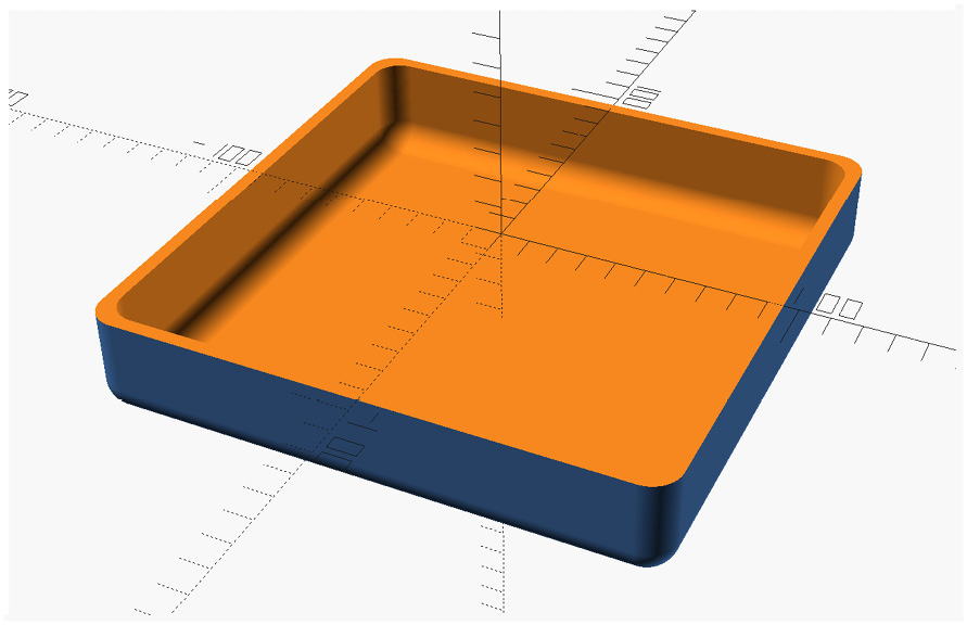
Figure 6.6 – The tray generated using create_tray() module
Now that we have created the tray for our desk drawer, it is time to add side rails and sliders to our design. This will allow us to mount our tray under a desk or table.
Using include or use
We can import the shapes.scad file into our design by using an include statement instead of use. The difference between the two is in how shapes.scad is implemented. Both statements will bring in all the modules from shapes.scad. However, the include operation will execute any code that sits outside of any modules in shapes.scad, while the use operation will not. The difference between the two will become clearer when we create our own library in the Creating our own OpenSCAD library section.
We will now turn our attention to using rails and sliders from the BOSL. We use the sliders.scad file for both. We start by adding rails to our drawer.
Adding rails to our drawer tray
The BOSL contains rails and sliders that we can use for our desk drawer. These parts give us the objects we need to allow our desk drawer to slide in and out from under our table or desk.
To add rails, follow these steps:
- Add the library for rails and sliders with the following code at the top of our file:
use <BOSL/sliders.scad>
- Comment out the create_tray(); line so that we can focus on the rails:
//create_tray();
- Add the following code:
rail(l=length-20, w=rail_size, h=rail_size);
What we have done here is to create a rail that is the length value of our drawer minus 20 mm. We make it shorter to account for the round corners of the tray. We have already declared rail_size to be 10 in our variable declarations, and we use this variable to define the width (w) and height (h) values of our rail.
- Click on Render or hit F6 on the keyboard (or F5 to preview if the design is taking too long to render). Observe the following shape:

Figure 6.7 – The rail generated using the BOSL Standard Library
- As we can see, we can use this shape for rails on our drawer. However, we must first put the shape in the right place. We want to encapsulate our code in a module as well. Delete the line rail(l=length-20, w=rail_size, h=rail_size); and add the following module below the create_tray() module:
module create_rail()
{
translate([width/2,0,-(rail_size/2)])
rotate([0,90,0])
rail(l=length-20, w=rail_size, h=rail_size);
}
What we have done here is rotate the rail to a position that will make it useful. We then move it to the right by half the width value, as the tray is positioned in the center of our design. We move it down by half of its height (rail_size/2) value so that it will be below the z axis and line up with our tray.
- Before we can see the results of our changes, we need to call create_rail() and uncomment out the create_tray() module:
create_tray();
create_rail();
- Click on Render or hit F6 on the keyboard (or F5 to preview if the design is taking too long to render). Observe the following shape:
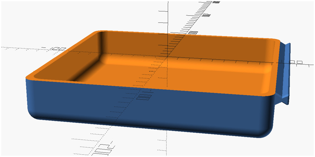
Figure 6.8 – The tray with a rail added
- As we can see, a rail has been added to the right side of our tray. We can modify the create_rail() module by adding code to put a rail on the left side as well; however, there is an easier solution. Modify the non-module code (code that sits outside of a module and is run when we render) to the following:
create_tray();
create_rail();
mirror([1,0,0])create_rail();
The mirror operation does exactly what its name implies – it creates a mirror of an object. The parameters determine where the mirroring occurs based on x, y, and z values. In our case, we are mirroring in the x direction.
- Click on Render or hit F6 on the keyboard (or F5 to preview if the design is taking too long to render). Observe that there are now two rails added to our tray:

Figure 6.9 – The tray with both rails added
As we can see, the rails give our drawer something to mount inside a slider. Before we create the sliders for mounting the rails, we will add a handle to the drawer.
Creating the handle for our drawer
To create a handle, we will use cuboid from the BOSL and cut away a portion of it. We will position this handle on the front of the drawer. We will place the code to do this in a module.
To create the handle, follow these steps:
- Create a new module below the create_rail() module with the following code:
module create_handle(size)
{
translate([0,-length/2,-(size*1.5)])
difference()
{
difference()
{
cuboid([5*size,3*size,1.5*size],
fillet=2);
scale([0.8,0.8,2])
cuboid([5*size,3*size,1.5*size],
fillet=2);
}
translate([0,size*50,0])
cube([size*100,size*100,size*100],
center=true);
}
}
There is a lot of code here. Let's step through it before we move on to implementing it. If we start with the second difference() operation, we can see that we take the difference between a cuboid created to be 5 times the size parameter in the x direction, 3 times in the y direction, and 1.5 times in the z direction, with a version of the same cuboid but 80% of its size in the x and y directions and 200% in the z direction.
These multiplication values are arbitrary and were chosen for the shape that they create. With the first difference() operation, we simply cut our handle in half with a box that is much bigger and moved over to be on one side of the y axis. We then moved the whole shape in place with the first translate() operation, placing it in front of our tray.
- To view our design so far, modify the non-module code to look like the following:
create_tray();
create_rail();
mirror([1,0,0])create_rail();
create_handle(10);
With create_handle(10);, we are creating a handle with a starting value of 10. The result will be a handle that is 50 mm in the x direction, 30 mm in the y direction, and 15 mm in the z direction.
- Click on Render or hit F6 on the keyboard (or F5 to preview if the design is taking too long to render). Observe that our drawer is now complete:

Figure 6.10 – The completed drawer design
For reference, here is a picture of a drawer that has been 3D-printed and painted:

Figure 6.11 – A 3D-printed desk drawer
Now that we have completed the drawer portion of our desk drawer, it is now time to design the sliders that allow the drawers to slide in and out under the table.
Creating the sliders for our desk drawer
As mentioned in the Adding rails to our drawer tray section, there are slider objects in the BOSL. We will create a slider and then move it into the correct position.
Let's get started:
- Create a new module with the following code:
module create_slider(offset)
{
base=20;
slider(l=length,h=rail_size,base=base,
wall=4,slop=offset);
}
What we are doing here is creating slider equal to the length value of the drawer with a base value of 20 mm. The offset value is used to create some space between the rail and the slider.
- To see the slider by itself, comment out all the other non-module code and add a call to the create_slider() module, as shown in the following snippet:
//create_tray();
//create_rail();
//mirror([1,0,0])create_rail();
//create_handle(10);
create_slider(0.4);
We are calling the create_slider() module with an offset value of 0.4. This value may be experimented with to provide a snug fit between the rail and the slider.
- Click on Render or hit F6 on the keyboard (or F5 to preview if the design is taking too long to render). Observe that we see a slider that looks like the following (ensure that we have use the line <BOSL/sliders.scad> at the top of our code):
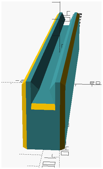
Figure 6.12 – A slider generated in OpenSCAD using the BOSL Library
- Now, we will move the slider into place. However, please note that this step is only necessary to check the fit; this is because when we 3D-print the slider, we do so separately from the drawer, as it is not attached to it. Change the code for create_slider() to the following:
module create_slider(offset)
{
base=20;
translate([width/2+(rail_size+base),0,
-rail_size/2])
rotate([0,-90,0])
slider(l=length,h=rail_size,base=base,
wall=4,slop=offset);
}
To understand what we just did here, let's work from the bottom to the top. With this change, we rotate slider -90 degrees on the y axis. We then move it to the right on the x axis by a value that is equal to half the width value (as the drawer is centered) plus the size of the rail and slider base added together (width/2+(rail_size+base)). We then move the slider down so that it lines up with the rail (-rail_size/2).
- To view all the parts we have so far, uncomment out the code commented in Step 2.Add a second create_slider() call and use the mirror operation to create a slider on the other side of the tray. Our non-module code should look like the following:
create_tray();
create_rail();
mirror([1,0,0])create_rail();
create_handle(10);
create_slider(0.4);
mirror([1,0,0])create_slider(0.4);
- Click on Render or hit F6 on the keyboard (or F5 to preview if the design is taking too long to render). Observe that the sliders have been created:

Figure 6.13 – The sliders generated and put in place
Now that we have created the sliders for our desk drawer, there is one task that remains. We need to create screw holes on the sliders so that they may be mounted onto the bottom of our desk or table.
In the next section, we will do just that.
Adding screw holes to the sliders
We will create a separate module to create the screw holes. We will then call that module from the create_slider() module. This will keep our code clean and also allow code re-use.
Let's get started:
- Between the last module and the non-module code, create a new module with the following:
module create_3mm_screw_hole()
{
union()
{
cylinder(d=3, h=500);
translate([0,0,-500])
cylinder(d=10, h=500);
}
}
- Comment out all the non-module code and put the following at the bottom:
//create_tray();
//create_rail();
//mirror([1,0,0])create_rail();
//create_handle(10);
//create_slider(0.4);
//mirror([1,0,0])create_slider(0.4);
create_3mm_screw_hole();
What we are doing here is simply creating two cylinders stacked together, one that is 3 mm in diameter and one that is 10 mm in diameter. The 3 mm hole is the actual hole our screw will go through; the 10 mm one is the countersink hole for the screw. We have made both cylinders extremely long to provide for clean cuts. The cylinders sit in the middle on the z axis.
- Click on Render or hit F6 on the keyboard (or F5 to preview if the design is taking too long to render). Observe that our cylinders reach above and below the view in the object display area:

Figure 6.14 – Cylinders created from the create_3mm_screw_hole() module
- We will now modify the code in the create_slider() module. Change the code in the module to the following:
module create_slider(offset)
{
base=20;
hole_inset=20;
difference()
{
translate([width/2+(rail_size+base),0,
-rail_size/2])
rotate([0,-90,0])
slider(l=length, h=rail_size,
base=base,wall=4, slop=offset);
translate([width/2+(rail_size+(base/2)),
(length/2)-hole_inset,-rail_size/2])
create_3mm_screw_hole();
translate([width/2+(rail_size+(base/2)),
-((length/2)-hole_inset),-rail_size/2])
create_3mm_screw_hole();
}
}
Before we render our design, let's go through the changes. Basically, what we are doing in the new create_slider() module is taking the difference between slider and a 3 mm screw hole. We have added a new variable called hole_inset, which is the value from the ends of the slider where we want to place our screw holes. In this case, we are putting our screw holes 20 mm from the ends. The translate() operation moves the holes to the base part of the slider, away from the side where the drawer will slide. The second translate() operation differs from the first by taking the negative value in the y direction to make a mirrored copy. The holes are then moved down in the z direction by half the rail_size value to countersink the screw hole.
- Before we render our design, we will uncomment out all the non-module code and delete the last non-module line we added in Step 2. Our non-module code should look like the following:
create_tray();
create_rail();
mirror([1,0,0])create_rail();
create_handle(10);
create_slider(0.4);
mirror([1,0,0])create_slider(0.4);
- Click on Render or hit F6 on the keyboard (or F5 to preview if the design is taking too long to render). Observe that our design is now complete, and the sliders now have screw holes with countersinks:
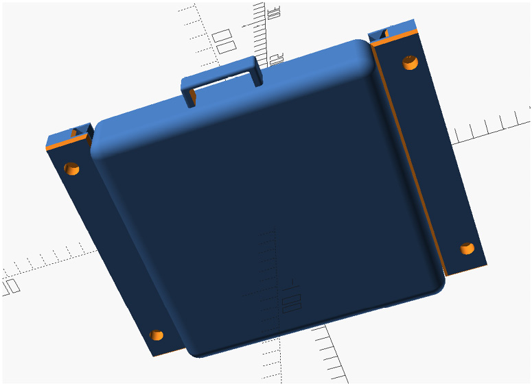
Figure 6.15 – The final design with screw holes
We have now finished our design of the desk drawer. As we can see, we are able to easily leverage the OpenSCAD standard library to create new and interesting designs.
In the next section, we will look at OpenSCAD Single Topic libraries.
Exploring OpenSCAD Single Topic libraries
Now that we understand how OpenSCAD standard libraries can be utilized to improve our designs, let's look at what are called OpenSCAD Single Topic libraries. As their name implies, OpenSCAD Single Topic libraries are used for specific purposes, such as creating a threaded nut for a design. There are six libraries listed on the OpenSCAD website (http://openscad.org/libraries.html) under Single Topic. We will look at the four most relevant (for our purposes) libraries:
- Round Anything
- Mark's Enclosure Helper
- The OpenSCAD threads.scad module
- The OpenSCAD smooth primitives library
Let's start with the Round Anything library.
Round Anything
The motivation behind the Round Anything library is, as its name implies, to round parts. Standard OpenSCAD code lacks the functionality for rounding basic shapes. Installing this library provides a good tool to use in our designs.
For our example, however, we will look at the shell2d() operation, which ironically does not round a part. With shell2d(), we create a hollow outline of a 2D shape. We can then use the gridpattern() operation from Round Anything to create a grid inside the new shape.
In Figure 6.16, we can see the effect of the shell2D() operation on a 2D sketch. The image on the left is the shape we created in Chapter 4, Getting Started with OpenSCAD, for the PVC hook. Applying the shell2D() and gridpattern() operations on this shape creates what we see on the right side:
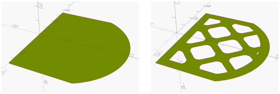
Figure 6.16 – The before and after shell2D() and gridpattern() operations
To create the shape on the right, follow these steps:
- Download and install the Round Anything library from this URL: https://openscad.org/libraries.html.
- Create a new design with the following code:
use <Round-Anything/roundAnythingExamples.scad>
shell2d(0, -5)
{
intersection()
{
translate([20,0])
circle(d=80);
translate([30,0])
square([60, 70], center=true);
}
gridpattern(iter=50);
}
In this code, we create square with one rounded side using the intersection() operation. We then wrap that inside the shell2d() operation with offset values of 0 and -5. This defines the thickness of the shell (negative numbers create the shell inward, and positive numbers outward). For these numbers, we will create a shell with an inside wall thickness of 5 mm. We then add gridpattern(iter=50); , which creates a pattern inside our shape.
- Click on Render or hit F6 on the keyboard (or F5 to preview if the design is taking too long to render). Observe that the pattern looks like the pattern on the right side in Figure 6.16.
- To experiment further, comment out the gridpattern() operation:
//gridpattern(iter=50);
- Click on Render or hit F6 on the keyboard (or F5 to preview if the design is taking too long to render). Observe that the 2D shape is a shell with a value of 5 mm from the outside edge inward:
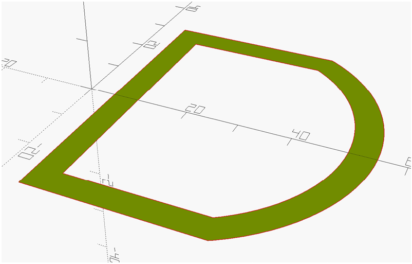
Figure 6.17 – The shape after the shell2D() operation without gridpattern()
There is much more functionality to the Round Anything library than we have touched on. What is important to gain from this exercise is the power that this external library can bring to our designs.
We will now look at a library that will build enclosures for us.
Mark's Enclosure Helper
With this library, we can easily create enclosures for our projects with a few lines of code. We can make enclosures with interlocking rims, snap-fit enclosures, and rounded corners.
For our example, we will create a simple hinged enclosure with a few lines of code. To create our hinged box, follow these steps:
- Download and install the Mark's Enclosure Helper library from this URL: https://openscad.org/libraries.html. Be sure to rename the folder from MarksEnclosureHelper-master to MarksEnclosureHelper.
- Create a new design with the following code:
include <MarksEnclosureHelper/hingebox_code.scad>
hingedbox( box_def );
hinge_points = [0.5];
hinge_len = 20;
What we have done here is define a standard hinged box enclosure. It may seem odd that we are simply setting variables without passing them into a module or operation, but take note of include at the top. This library relies heavily on code that is written outside of modules. If we were to replace include with use, the code will not work. The hinge_points variable defines where the hinges are located, with the 0.5 value putting them in the middle of the enclosure. The hinge_len variable defines the size of the hinge, which we set to 20.
- Click on Render or hit F6 on the keyboard (or F5 to preview if the design is taking too long to render). Observe the enclosure created:

Figure 6.18 – The enclosure generated using the Mark's Enclosure Helper library
A common task among makers with 3D printers is creating enclosures for various projects. Having a library that does this with ease is a great tool to have.
Now that we know how to create quick enclosures, let's turn our attention to creating screws and bolts that we can use in our designs.
The OpenSCAD threads.scad module
The OpenSCAD threads.scad library is designed to be an efficient way to generate bolts, threaded rods, and nuts that we can use in our projects.
In our example, we will create a 25 mm M10 bolt with a couple of lines of code. Let's get started:
- Download and install the OpenSCAD threads.scad library from this URL: https://openscad.org/libraries.html.
- Create a new design with the following code:
use <threads.scad>
MetricBolt(10, 25, tolerance=0.4);
This code couldn't be simpler. We pass in 10 for the diameter and 25 for the length. We can adjust tolerance if we are finding our 3D prints of this bolt too tight or too loose.
- Click on Render or hit F6 on the keyboard (or F5 to preview if the design is taking too long to render). Observe that an M10 25 mm bolt is generated:
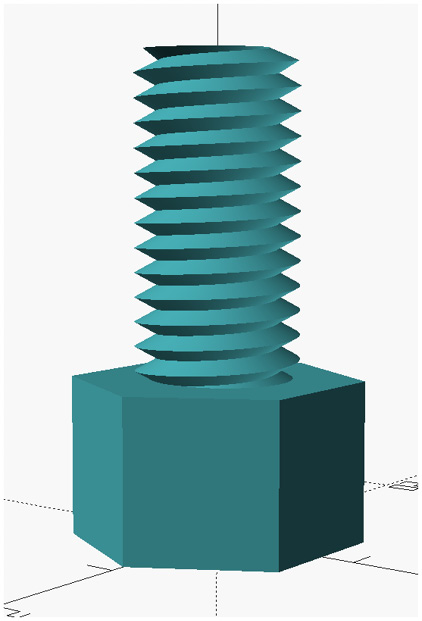
Figure 6.19 – An M10 25 mm bolt generated from the OpenSCAD threads.scad library
- As we can see in the first line of the code in Step 2, the threads.scad library is brought into our program with the use command. If we were to change this to include, we would see a demo of the library. To verify this, change the code to the following:
include <threads.scad>
MetricBolt(10, 20, tolerance=0.4);
- Click on Render or hit F6 on the keyboard (or F5 to preview if the design is taking too long to render). Observe that many parts are generated, including our M10 25 mm bolt:
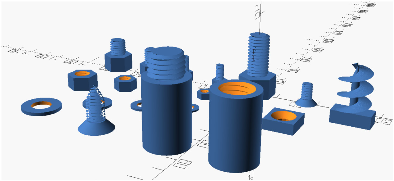
Figure 6.20 – A generated demo of parts from the OpenSCAD thread.scad library
Now that we can see there is an easy way to generate threaded nuts and bolts, let's turn our attention to a library that generates smooth basic objects for us.
The OpenSCAD smooth primitives library
This library provides common primitive shapes with additional parameters to smooth out the shape. As many of us know, it is not always easy to round off or smooth an edge of a common shape in OpenSCAD. Although this library is not vast, it does provide a few useful shapes that we can implement in our designs.
For our example, we will look at SmoothCylinder. To explore this, follow these steps:
- Download and install the OpenSCAD smooth primitives library from this URL: https://openscad.org/libraries.html.
- Create a new design with the following code:
use<smooth_prim.scad>
SmoothCylinder(10, 30, 5);
In the code, we are creating SmoothCylinder with a radius of 10 mm, a length of 30 mm, and a smoothing radius of 5 mm.
- Click on Render or hit F6 on the keyboard (or F5 to preview if the design is taking too long to render). Observe that a cylinder with rounded edges is rendered:
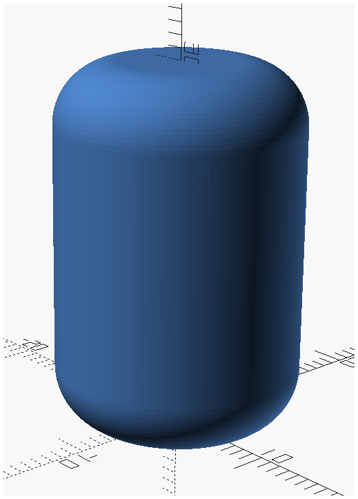
Figure 6.21 – SmoothCylinder generated with the OpenSCAD smooth primitives library
It is easy to see how we can use SmoothCylinder in our OpenSCAD designs and how easy it is to create one. For example, by cutting SmoothCylinder in half and hollowing it out, we can create a bell jar-style cover for a project.
Now that we have a deeper understanding of how to use external libraries, let's create one of our own. We will use the code we wrote to create the desk drawer in the Using the BOSL to design a desk drawer section.
Creating our own OpenSCAD library
One way to turn our desk drawer code into a library file is to add it to our OpenSCAD installation's libraries directory. We can open this location on our computer by clicking on File | Show Library Folder... in OpenSCAD.
Before we do that, we should take note of how we will be using this library. If we were to simply copy the code as we left it in the Using the BOSL to design a desk drawer section, we could see the whole drawer with the sliders generated. This would happen when using an include statement for importing:
include <desk_drawer.scad>
This is due to the non-module code at the end of the file that creates the drawer and the sliders we added in the Using the BOSL to design a desk drawer section. We will, however, be able to change the size of the drawer and sliders, as we will have access to the non-module variables declared at the beginning of the desk_drawer.scad library file. This may seem like the way we should approach creating our own OpenSCAD library file. However, it would make little sense when it comes to 3D printing, as our 3D file export (.stl, .3mf) would have both the drawer and the sliders together. This would prove difficult to 3D-print as separate parts.
Another solution is to bring our library file into our new file with the use statement:
use <desk_drawer.scad>
With this approach, we solve the issue of the drawer and sliders rendered together, but we do not have access to the variables that would allow us to change the size of the drawer. Also, we would expect the user of this library to know which modules to call to build the various components of the drawer, such as create_tray() and create_rail(), and the corresponding mirror operation for creating the opposite side rail. The drawer would always be the size set by the variables at the beginning of the file unless we changed the input parameters for the modules to accept values for length, width, and height. This would add extra complexity for anyone using this library.
The best solution is to modify our file and instruct our user to use our library like any other OpenSCAD library by using the include statement.
Let's do just that:
- Create a copy of the desk_drawer.scad file and call it desk_drawer_lib.scad.
- Save desk_drawer_lib.scad in the OpenSCAD libraries folder.
- In desk_drawer_lib.scad, remove all the non-module code from the bottom of the file. Do not remove the variable declarations from the top of the file.
- We will now create two new modules that will make using this library easier. We will start with a module to create the drawer. Add the following to the bottom of the code:
module create_drawer()
{
create_tray();
create_rail();
mirror([1,0,0])create_rail();
create_handle(10);
}
- To create the sliders at the side of the drawer, we will add a new module. Add the following module to the bottom:
module create_sliders(offset=0.4)
{
create_slider(offset);
mirror([1,0,0])create_slider(offset);
}
- Take note of the plural in the name of our new module and the default value of 0.4 for offset. This will make the library a little easier to use, as the user will not have to remember to supply an offset value. For good measure, we should add a default value to the original create_slider()module so that it looks like the following:
module create_slider(offset=0.4)
{
base=20;
translate([width/2+(rail_size+base),0,
-rail_size/2])
rotate([0,-90,0])
slider(l=length,h=rail_size,base=base,
wall=4,slop=offset);
}
This new offset value makes the library a little easier to use for calls to create_slider(). We use create_slider() when we need to generate a single slider.
- We are now ready to use our new library. Create a new file in OpenSCAD with the following code:
include <desk_drawer_lib.scad>
width=500;
create_drawer();
create_sliders();
With this code, we import our library, and then we set the width value to 500. We then create the drawer and the sliders.
- Click on Render or hit F6 on the keyboard (or F5 to preview if the design is taking too long to render). Observe that a new desk drawer complete with sliders is generated and that its width is greater than its length:

Figure 6.22 – A wide drawer generated with the custom OpenSCAD library
By arranging our library code this way, it becomes easy to generate objects for 3D printing. For example, if we wanted to print a single slider, we could generate one with this code:
create_slider();
- Click on Render or hit F6 on the keyboard (or F5 to preview if the design is taking too long to render). Observe that a single slider is generated:
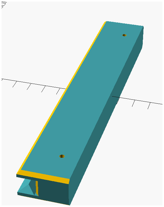
Figure 6.23 – A single slider generated with the custom OpenSCAD library
- To generate a .stl file for 3D printing, click on the Export as STL button in the editor or hit F7 on the keyboard.
- Save the .stl file. We can view it with an STL viewer, such as 3D Viewer in Windows or Preview in macOS:
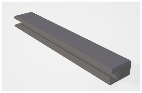
Figure 6.24 – A slider as a .stl view in 3D Viewer in Windows
With our object stored as a .stl file, we can then proceed to load it into a slicer program, such as Cura, and prepare it for 3D printing.
Having our desk drawer code as an installed library means we can utilize it to generate desk drawers easily. This allows us to place such a component in larger designs – for example, a design of an entire workshop.
The ability to see our designs before construction is the power of OpenSCAD and CAD design in general. It limits any measurement mistakes and, thus, any post-construction modifications.
Summary
In this chapter, we introduced external libraries to our designs. We were able to use the BOSL to design a desk drawer that slides on sliders under our desk. We also explored many of the libraries available from the OpenSCAD website, noting the design inspirations and strengths of the libraries.
We were able to then take the code written for our desk drawer design and implement it as an OpenSCAD library. As we saw, doing this greatly simplifies future designs. It allows us to design something rather complex by breaking it down into separate components.
With this chapter, we come to the end of the second part of this book, Learning OpenSCAD, where we explored OpenSCAD from basic to more complex concepts. We will use this knowledge in the third part of this book, Projects, as we use OpenSCAD to design and then bring our designs to life through 3D printing.