Chapter 9: Designing and Printing a Model Rocket
On October 4th, 1957, the Soviet Union became the first country on Earth to launch a satellite into orbit with Sputnik 1. This set in motion a space race between the Soviet Union and the United States, which ultimately saw American men walk on the moon on July 20th, 1969. The hobby of model rocketry was born from this era. Rockets designed and built from lightweight materials such as plastic, balsa, and paper made model rocketry a safe and educational endeavor, inspiring many young people to opt for STEM (science, technology, engineering, and math) fields. In fact, many credit this time in history for the amazing technological innovations we have today.
Early model rockets were built using paper tubes, lathe-spun balsa nose cones, and hand-cut balsa fins. In this chapter, we will use 21st-century 3D design and 3D printing technology to create our own model rocket from a discarded paper towel tube.
We will cover the following topics:
- Creating the motor mount
- Creating the nose cone
- Creating the fins
- Assembling and launching the model rocket
Technical requirements
The following is required to complete the chapter:
- Any late-model Windows, macOS, or Linux computer that can install OpenSCAD and Cura.
- 3D printer with ABS and PLA – any FDM printer should work; however, the Creality Ender 3 V2 is the printer used for our example.
- Paper tube from paper towel roll (referred to as the body tube).
- 3 mm drill tap.
- 2 M3 10 mm bolts.
- Digital caliper for measurement.
- Epoxy glue and popsicle stick.
- 1 meter of elastic cord.
- Model rocket parachute – https://bit.ly/3pVz1aY or https://www.youtube.com/watch?v=Y3xhZpmmboE.
The code and images for this chapter may be found here: https://github.com/PacktPublishing/Simplifying-3D-Printing-with-OpenSCAD/tree/main/Chapter9.
Creating the motor mount
The motor mount of the model rocket is used to secure the model rocket motor in place inside the body tube. We will be constructing the motor mount from two rings connected by posts. The top ring will have a hole for the ejection charge of the rocket motor. The bottom ring will have a hole for the nozzle at the bottom of the model rocket motor. We will start our motor mount design by taking measurements of the paper tube.
Building around the paper tube
For those familiar with model rocketry, it is quite often the case that a simple paper tube from a paper towel roll does not fit with existing model rocket parts. However, with OpenSCAD and a 3D printer, we may custom build parts to fit any paper tube. We will design our nose cone, fin can, and motor mount around the paper tube, starting with the motor mount.
To design the motor mount, we need to get an accurate measurement of the internal diameter of the paper tube. To do this, we will build a measurement tool to assist us. We will start with a rough measurement of the internal diameter using a digital caliper.
Measuring the paper tube
Due to the lack of rigidity of paper tubes, getting exact measurements is a difficult thing to do. Any measurement we do get will be affected by how much we distort the paper tube while taking the measurement. The number we get will not be exact; however, it will be close enough to use as a starting point in our design.
To get the first measurement, use a digital caliper to measure the internal diameter of the paper tube. Be sure not to squeeze the paper tube to prevent distorting, as shown in the following figure:
Figure 9.1 – Measuring the internal diameter of a paper tube
For our tube, we measured an internal diameter of 40.7 mm. We will use this value to write code to generate the measurement tool.
Designing the measurement tool
The tool we will build to measure the internal diameter of the paper tube will be a cone-shaped cylinder. By inserting this shape into the paper tube, we may get a more accurate measurement than with our previous method. To build the measurement tool, we do the following:
- Open up OpenSCAD and create a new file.
- For our example, the internal diameter was measured at 40.7 mm. We will use this value in our code. Add the following code to our new OpenSCAD file:
$fn=200;
d_tool=40.7;
d_tool_offset=3;
tool_height=60;
module create_measurement_tool()
{
cylinder(h=tool_height,
d1=d_tool+d_tool_offset,
d2=d_tool-d_tool_offset);
}
In our code, we have a module called create_measurement_tool() to create a cone-shaped cylinder with one end 3 mm larger than the measured value (d_tool) and the other 3 mm smaller than the measured value. We set the height of our tool to 60 mm using the tool_height variable. To generate the measurement tool, add the following code in the editor:
create_measurement_tool();
- Click on Render or hit F6 on the keyboard to observe the following:
Figure 9.2 – Tool to verify paper tube internal diameter
- Hit F7 on the keyboard and save the .stl file to the computer. Give it a descriptive name such as measurement_tool.stl.
With the .stl file saved to our computer, it is now time to print out and use the measurement tool to get an accurate internal diameter of the paper tube. We will use Cura to slice our object to G Code.
Printing out and using the measurement tool
We will print out our measurement tools in a light-colored Polylactic Acid (PLA). We will use a raft to avoid the elephant's foot effect and to provide strong bed adhesion.
What Is the Elephant's Foot Effect in 3D Printing?
The elephant's foot effect in 3D printing refers to the warping of the first few layers during a print job due to a lack of space between the print bed and nozzle. This warping takes its name from the shape of an elephant's foot. Often it is necessary to have the first layer "pushed" onto the print bed to gain adhesion, which can lead to the elephant's foot effect.
We will start by modifying a generic PLA profile:

Figure 9.3 – Generic PLA material profile
- Set Build Plate Adhesion Type to Raft.
- Using what we learned in Chapter 3, Printing Our First Object, print out the measurement tool using a light-colored PLA.
- Once printed, insert the measurement tool into the paper tube and make a mark on the measurement tool right where it meets the paper tube (see Figure 9.4 a).
- Using the digital caliper, take a measure where the marking is made. This will be the value we use to create our motor mount (see Figure 9.4 b):

Figure 9.4 – Taking measurements of the paper tube using the measurement tool
With an accurate measurement of the internal diameter of the paper tube, we may now design and print the motor mount.
Designing and printing the motor mount
By using a standard paper tube from a paper towel roll, we will be making a model rocket that is considered larger than most model rockets. To successfully launch this rocket, we will require a C- or D-size model rocket motor, and thus our motor mount must accommodate for this.
What Does the Letter of a Model Rocket Motor Mean?
The letter used to classify a model rocket motor refers to the motor's total impulse range. Total impulse is the maximum momentum for a motor measured in newton-seconds. One newton-second is used to describe a force of one newton on an object for one second. A C motor has a total impulse range of 5.01–10 newton-seconds, while a D motor has a total impulse range of 20.01–40 newton-seconds. A good source of information for model rocketry is the Sigma Rockets YouTube channel (which yours truly helped to create): http://www.youtube.com/sigmarockets.
As C motors are generally 18 mm in diameter and D motors 24 mm in diameter, we will design our code to be dynamic enough to generate a motor mount for either size. We will use a conditional statement in our code to do this.
Writing code to generate a motor mount
With an accurate internal diameter measurement, we may now proceed to design the motor mount. We will design the motor mount to fit a standard 18 mm model rocket motor by default. We will use an if statement in our code to modify the motor mount to suit a 24 mm model rocket motor if desired.
We will parameterize our code with the following values:
- d_actual – The internal diameter of the paper tube as measured using the measurement tool.
- motor_height – The height of the model rocket motor. This value is 70 mm for both 18 mm and 24 mm motor rocket motors.
- motor_diameter – The default model rocket motor diameter. We will add an additional 0.5 mm to this value.
- thrust_ring – The thrust ring is used to keep the model rocket motor from moving up the paper tube. Its size, coupled with the motor_diameter, matches the thickness of the tube used in the model rocket motor. We will use a default value of 14 mm for an 18 mm model rocket motor.
- ring_thickness – This is the thickness of the top and bottom rings used in the motor mount.
- screw_hole_distance – This is the distance of the screw hole from the center. M3 10 mm bolts will be used to secure the model rocket motor in place.
- mount_post_diameter – This is the diameter of the posts that will connect the top and bottom rings together.
The following diagram illustrates the parameters used in designing our motor mount:
Figure 9.5 – Motor mount dimensions (not to scale)
Now we will start writing the code to create the centering ring, followed by motor mount posts.
Creating the centering ring
The centering ring is the centering adapter between the model rocket motor and the paper tube. For our motor mount, we will require two centering rings. In our code, we will define the variables used for the entire motor mount before writing the code for the centering ring.
We will start by creating a new OpenSCAD file:
- Open up OpenSCAD and create a new file.
- At the top of the file, add the variable declarations:
$fn=200;
d_actual=41.7;
motor_height=70;
motor_diameter=18.5;
thrust_ring=14;
ring_thickness=4;
screw_hole_distance=16;
mount_post_diameter=15;
- In the editor, add the following code:
module create_centering_ring()
{
difference()
{
cylinder(h=ring_thickness, d=d_actual);
translate([0,0,ring_thickness/2])
cylinder(h=500, d=motor_diameter);
cylinder(h=500, d= thrust_ring, center=true);
}
}
create_centering_ring();
- With this code, we create a ring with an internal indent equal to the diameter of an 18 mm model rocket motor (plus 0.5 mm). Click on Render or hit F6 on the keyboard and observe the centering ring:

Figure 9.6 – 18 mm centering ring
- As we want our code to produce 24 mm model rocket motors as well, we will add a new variable called type. If type is equal to 18 (as in 18 mm), we will generate an 18 mm centering ring (as in Figure 9.6); if not, we will generate a 24 mm centering ring. Change the code for the module create_centering_ring() and the call to this module to the following:
module create_centering_ring(type=18)
{
difference()
{
cylinder(h=ring_thickness,d=d_actual);
if(type==18)
{
translate([0,0,ring_thickness/2])
cylinder(h=500,d=motor_diameter);
cylinder(h=500,d=thrust_ring,
center=true);
}
else{
translate([0,0,ring_thickness/2])
cylinder(h=500,d=motor_diameter+6);
cylinder(h=500,d=thrust_ring+6,
center=true);
}
}
}
create_centering_ring(24);
- We add 6 to the value of motor_diameter and thrust_ring if type is not equal to 18. This will generate a centering ring for a 24 mm model rocket motor. Click on Render or hit F6 on the keyboard and observe that a centering ring for a 24 mm model rocket motor is generated:

Figure 9.7 – 24 mm centering ring
With the code to generate the centering ring written, it is time to add the side posts that will hold the model rocket motor in the paper tube.
Creating the motor mount posts
We will add two posts to the centering ring. The posts will also be used to connect a bottom centering ring to the motor mount.
To write the code to create the motor mount post, do the following:
- Delete the line create_centering_ring(24);.
- Add the following module:
module create_mount_post(type=18)
{
difference()
{
translate([screw_hole_distance,0,0])
cylinder(d=mount_post_diameter,
h=motor_height);
if(type==18)
{
cylinder(d=motor_diameter, h=500,
center=true);
}
else
{
cylinder(d=motor_diameter+6, h=500,
center=true);
}
difference()
{
cylinder(d=1000, h=500,
center=true);
cylinder(d=d_actual, h=500,
center=true);
}
}
}
With this module, we create a cylinder of diameter mount_post_diameter and a height of motor_height. We then move the cylinder in the x axis by the value of screw_hole_distance (we will use this variable to place the screw holes later in the code). We cut the post on one side with a cylinder equal to either 18 mm or 18 + 6 mm based on the value of type. We then use a hollow cylinder with an internal diameter equal to the internal diameter of our paper tube to create the final shape.
- Add the following line to the code:
create_mount_post(24);
This will generate a motor mount post for a 24 mm model rocket motor.
- Click on Render or hit F6 on the keyboard and observe the following:

Figure 9.8 – Motor mount post
- Before we add the post to the centering ring, we need a module for screw holes. Add the following module to the code:
module create_screw_holes(diameter)
{
translate([screw_hole_distance,0,0])
cylinder(d=diameter, h=500, center=true);
translate([-screw_hole_distance,0,0])
cylinder(d=diameter, h=500, center=true);
}
This module is very similar to the screw hole module from the Adding a connector plate section of Chapter 8, Designing and Printing a Laptop Stand. Basically, it creates a cylinder with a large height with a diameter determined by the diameter variable. It is moved in the x direction by the value of screw_hole_distance. The cylinder is centered to allow for a clean cut. It is then mirrored so that two screw holes may be generated.
- We may now write the code to add a centering ring to motor mount posts. Add the following module to the code:
module create_main_bracket(type=18)
{
difference()
{
union()
{
mirror([1,0,0])
create_mount_post(type);
create_mount_post(type);
}
create_screw_holes(2.5);
}
create_centering_ring(type);
}
The create_main_bracket() module generates two motor mount posts and adds 2.5 mm screw holes through a difference() operation. A centering ring is then added.
- Replace the create_mount_post(24); line with the following:
create_main_bracket(24);
With this line, we will create a motor mount main bracket for a 24 mm model rocket motor.
- Click on Render or hit F6 on the keyboard and observe the following:

Figure 9.9 – Motor mount main bracket
- Before we write the code to finish the motor mount, we will save the motor mount main bracket as an .stl file. Hit F7 on the keyboard and save the file to the computer. Give it a descriptive name such as main-bracket.stl.
- To complete the motor mount, we require a bottom centering ring to hold the motor in place. Add the following module to the code:
module create_bottom_bracket(type=18)
{
difference()
{
create_centering_ring(type);
create_screw_holes(3);
rotate([0,0,90])
create_screw_holes(6);
}
}
The create_bottom_bracket() module generates a centering ring with two sets of screw holes. One set (3 mm) to screw the bottom bracket onto the main bracket and the other (6 mm) to act as air holes to help cool the model rocket motor after flight.
- Replace the create_main_bracket(24); line with the following:
create_bottom_bracket(24);
With this line, we will create a bottom bracket for a 24 mm model rocket motor.
- Click on Render or hit F6 on the keyboard and observe the following:
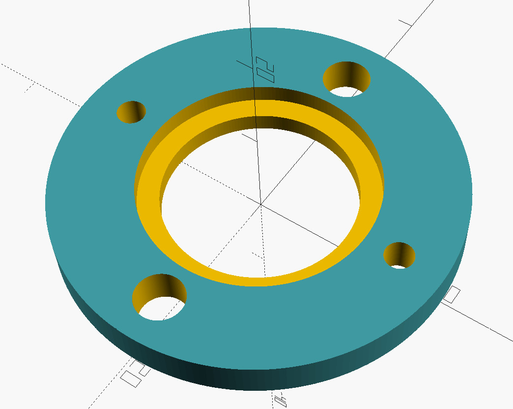
Figure 9.10 – Motor mount bottom bracket
- Hit F7 on the keyboard and save the file to the computer. Give it a descriptive name, such as bottom-bracket.stl.
With the bottom bracket generated and saved, we are now ready to print out the motor mount.
Printing out and installing the motor mount
As our motor mount will be touching the model rocket motor, we want it to be as resistant as possible to high temperatures. Ideally, we would print it with a liquid resin printer and an engineering-grade resin; however, as we are dealing with FDM printers, we will use a filament.
ABS melts at a higher temperature than PLA, is relatively inexpensive, and is readily available. Saying that, however, ABS can be a challenge to print with. An enclosure of some sort is desired to avoid the cracking that can occur as the ABS cools while printing (see Figure 9.11):
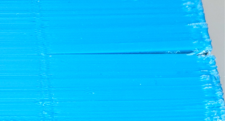
Figure 9.11 – ABS cracking
For our motor mount, small cracks would be acceptable as the motor mount will be inserted inside the paper tube. We will print with a draft shield to protect the print during the print job. An enclosure such as a tent enclosure is strongly recommended.
We will start by modifying a generic ABS profile:
- Open up Cura and select the generic PLA profile by selecting Material | Generic | ABS.
- Ensure that All settings are selected:
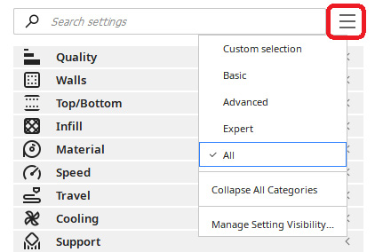
Figure 9.12 – Selecting All in Cura
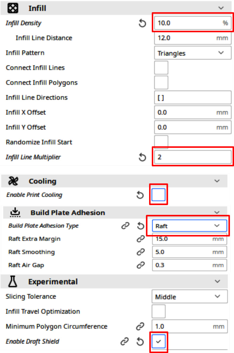
Figure 9.13 – Cura settings for ABS
Of note is the Enable Draft Shield setting under the Experimental section. This will create a shield around the print during the print job, protecting the print from cool air that might cause cracking.
- Import the motor mount main bracket and motor mount bottom bracket into Cura using the File | Open File(s)... menu option.
- For our example, we will load the 24 mm version of the motor mount parts. Click on the blue Slice button on the bottom-right part of the screen.
- Click on the Preview button to observe what our print job will look like:

Figure 9.14 – Preview of the motor mount print job
- Using what we learned in Chapter 3, Printing Our First Object, run the print job using ABS filament.
- After the print is done, we will tap thread holes into the mount posts. Using a 3 mm drill tap, add threads to both posts:
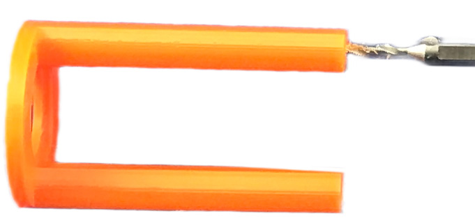
Figure 9.15 – Adding threads to the motor mount
- We will now glue the motor mount into the paper tube. Using a popsicle stick, spread a thin layer of epoxy glue about 60 mm inside the paper tube:
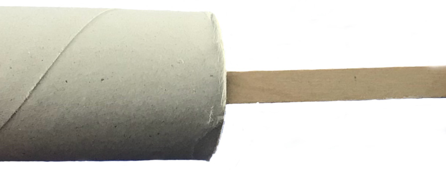
Figure 9.16 – Adding glue to the paper tube
- Install the motor mount main bracket into the paper tube such that the motor mount posts are flush with the bottom of the paper tube:
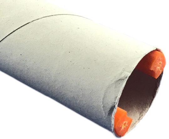
Figure 9.17 – Installing the motor mount main bracket
- Using M3 10 mm bolts, attach the motor mount bottom bracket to the motor mount main bracket. The bottom bracket will be removed and re-attached when installing the model rocket motor:
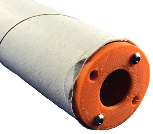
Figure 9.18 – Attaching the bottom bracket
With the motor mount installed, it is now time to take an accurate outside diameter measurement of the paper tube.
Getting an accurate outside diameter measurement
With the motor mount installed, an accurate measurement of the outside diameter of the paper tube may be taken by following these steps:
- Using a digital caliper, take the outside diameter measurement against the inside centering ring:
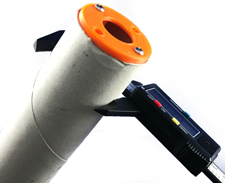
Figure 9.19 – Taking the outside diameter measurement of the paper tube
- In our example, we measure the outside diameter at 42 mm. We will add 0.5 mm to this value for a buffer.
We will use this measurement when we write the code to generate the nose cone and fins.
Creating the nose cone
The nose cone sits on top of the rocket and has a shape that reduces the aerodynamic drag on the rocket as it goes up. It attaches to the rocket through a shock cord and is jettisoned from the rocket when the ejection charge of the rocket motor is fired. A parachute attached to the shock cord brings the rocket down safely.
We will build the nose cone in two parts – the shoulder and the cone. Then we will print the nose cone. Let's start by building the shoulder.
Designing the nose cone
In the Printing out and using the measurement tool section, we measured an accurate internal diameter of the paper tube. We will use this value to create the shoulder part of the nose cone. We will also use the measured outside diameter taken in the Getting an accurate outside diameter measurement section.
The variables we will use to create the nose cone are the following:
- diameter_in – This is the internal diameter of the paper tube and will be used to create a nose cone shoulder.
- diameter_out – This is the outside diameter of the paper tube. It will be used for the cone shape part of the nose cone.
- cone_height – The height of the cone part of the nose cone or the part that sits outside of the paper tube.
- shoulder_height – The height of the shoulder part of the nose cone.
- taper – The value subtracted from diameter_in to create a taper at the bottom of the nose cone shoulder. The taper allows the nose cone to slide into the paper tube with ease.
We will start by creating a new file in OpenSCAD:
- Open up OpenSCAD and create a new file.
- At the top of the file, add the variable declarations:
$fn=200;
diameter_in=41.7;
diameter_out=42.5;
cone_height=65;
shoulder_height=20;
taper=1;
- Add the following code after the variable declarations:
module create_shoulder()
{
difference()
{
cylinder(h=shoulder_height,
d1=diameter_in-taper,
d2=diameter_in);
rotate([0,90,0])
linear_extrude(height=10, center=true)
difference()
{
circle(15);
circle(5);
}
}
}
The create_shoulder() module creates a cylinder with a slight cone shape. The bottom diameter is set to 1 mm less (taper) than the internal diameter of the paper tube, and the top is equal to the internal diameter. A sideways ring is subtracted from this shape to provide a channel to thread the shock cord through.
- Add the following code below the module:
create_shoulder();
- Click on Render or hit F6 on the keyboard to observe the nose cone shoulder:

Figure 9.20 – Nose cone shoulder
- With the nose cone shoulder in place, it is time to add the cone to the top. Add the following module to the code before the create_shoulder(); line:
module create_cone()
{
translate ([0,0,shoulder_height])
resize([diameter_out,
diameter_out,
cone_height])
difference()
{
sphere(d=diameter_out);
translate([0,0,-500])
cube([1000,1000,1000],center=true);
}
}
The create_cone() module creates a cone by stretching a sphere by the value of cone_height. The diameter of the cone is set to the measure outside diameter of the paper tube (diameter_out). A large cube is used to remove the bottom part of the stretched sphere to create a cone. The entire shape is moved up by the value of shoulder_height to place it on top of the nose cone shoulder.
- Add a call to create_cone() to the code. Our nose cone is created with the following two lines of code:
create_shoulder();
create_cone();
- Click on Render or hit F6 on the keyboard to observe the creation of the nose cone:

Figure 9.21 – Nose cone
- Hit F7 on the keyboard and save the file to the computer. Give it a descriptive name, such as nosecone.stl.
With the nose cone created, it is time to 3D print it.
Printing out the nose cone
With the nose cone .stl file created, we will now print out the nose cone. We will use PLA as it is easier to print with than ABS.
As in our previous print jobs, we will start with a generic template and modify it to our needs. We will use the generic PLA template:
- Open up Cura and select the generic PLA profile by selecting Material | Generic | PLA.
- Set Infill Density to 10% and Infill Line Multiplier to 2 under the Infill settings:
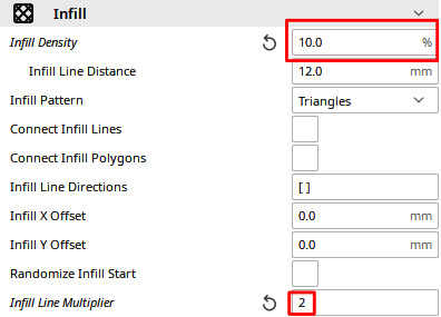
Figure 9.22 – Modified Infill settings
- Load the nose cone into Cura using the File | Open File(s)... menu.
- Click on the blue Slice button on the bottom-right part of the screen to create the print job.
- Using what we learned in Chapter 3, Printing Our First Object, run the print job using PLA filament.
With the nose cone designed and printed, it is now time to create the fins for our model rocket. Let's do that now.
Creating the fins
Traditionally, fins for model rockets were cut from thin balsa sheets and glued to the body tube of the rocket. Early kits provided cut-out patterns from paper that were traced onto the balsa sheet and cut out with a sharp hobby knife. When laser cutters became available, these fins were pre-cut out of balsa sheets, making it faster and easier for the kit builder to build their model rocket.
Still, the challenge with balsa fins was in gluing them to the body tube as they took a long time to dry. Getting the fins straight also proved to be difficult at times.
Plastic fin cans (fins pre-attached to a tube) make putting fins on a model rocket much easier. Armed with OpenSCAD and a 3D printer, we can easily create our own fin cans.
Let's do that now.
Designing the fin can
Our fin can will be designed such that we may alter the number of fins generated. A "launch lug," or small tube to hold the rocket on the launchpad for the first meter or so of flight, will be built into the fin can.
What Is a Launch Lug?
A launch lug is a fancy name for a paper-coated straw that generally is glued mid-way onto the body tube of a model rocket. The paper coating allows it to be glued onto the body tube with standard white glue. For larger rockets, it is common to break the launch lug up into multiple pieces on the body tube. For our example, we will build the launch lug onto the fin can, to keep things simple.
For our design, we will be using the OpenSCAD polygon operation to define the fin shape. This operation allows us to create a shape by passing in x and y coordinates. We will also use a for loop to dynamically generate the number of fins we want.
The variables we will use are the following:
- height – The height of the cylinder of the fin can as well as the length of the leading edge of a fin
- diameter – The internal diameter of the fin can
- thickness – The value to determine the thickness of the fins, fin can cylinder, and launch lug
- guide_diameter – The diameter of the launch lug or guide
- fins – The number of fins that will be generated for our fin can
- fin_shape – The x, y coordinates to determine the shape of the fin
We will start by verifying the fin shape.
Generating the fin design using the polygon operation
The fin_shape parameter defines the coordinates to draw out the fin design. By using the height parameter inside the fin_shape coordinates, we ensure that the leading edge of the fin or the edge that connects to the fin can cylinder is always the same height as the tube.
Let's start the design of our fin can by viewing the shape of the fin. We will start with a new OpenSCAD file:
- Open up OpenSCAD and create a new file.
- At the top of the file, add the variable declarations:
$fn=200;
height=70;
diameter=43.5;
thickness=1.2;
guide_diameter=3;
fins=3;
fin_shape=[[0,0],[height,0],
[100,35],[100,45],
[35,35]];
- With the variable declarations in place, let's verify the shape of the fin. We will use OpenSCAD's polygon operation on the fin_shape variable to do so. Type in the following code below the variable declarations:
polygon(fin_shape);
- Click on Render or hit F6 on the keyboard to observe the shape of the fin:

Figure 9.23 – Fin shape generated with the polygon operation
With our fin shape defined, let's create a module that will create a 3D version of the fin.
Extruding the fin design into a 3D shape
With the polygon operation, we can see a 2D shape of the fin design. To turn this design into a useful 3D shape, we simply extrude it and put the extruded shape in place with rotate and translate operations.
Let's do that with a new module in our code:
- Delete the polygon(fin_shape); line and replace it with the following module:
module create_fin(angle=0){
rotate([0,0,angle])
translate([diameter/2,0,height])
rotate([90,90,0])
linear_extrude(height=thickness, center=true)
polygon(fin_shape);
}
To understand this code, let's work from the bottom to the top. The linear_extrude() operation makes a 3D version of the polygon of fin_shape. It is extruded by the value of thickness and is centered. The fin is rotated with the rotate() operation such that it sits upright in the x and y axis (rotate([90,90,0])). It is then moved in the x axis equal to the radius of the fin can and up in the z axis by the value of height (translate([diameter/2, 0, height])). The rotate([0,0,angle]) operation rotates the extruded fin by an angle equal to the angle parameter (with a default value equal to 0) passed into the module in the z direction.
- To test out this module, add the following line to the bottom of the code:
create_fin();
- Click on Render or hit F6 on the keyboard to observe the extruded fin. Observe how it has been rotated and then moved away from the x and z axes:

Figure 9.24 – Extruded fin
With the code to extrude and move the fin into place, it is now time to finish the design of the fin can. We will create a new module to do that.
Creating the fin can from extruded fins
We will now create a new module to generate the fin can using the create_fin() module. The create_fin() module will be called for every fin we need to generate as determined by the fins parameter (set to 3 in our variable declarations). To do so, we do the following:
- Delete the create_fin(); line and replace it with the following module:
module generate_fin_can()
{
difference(){
union()
{
cylinder(h=height,
d=diameter+thickness);
for ( i = [0 : fins-1] ){
create_fin(i*(360/fins));
}
rotate([0,0,180/fins])
translate([diameter/2+
guide_diameter/2+thickness/2,
0, 0])
difference(){
cylinder(h=height,
d=guide_diameter+thickness);
cylinder(h=height,
d=guide_diameter);
}
}
cylinder(h=1000, d=diameter, center=true);
}
}
At the heart of this module is a for loop that places fins evenly around the fin can with the line create_fin(i*(360/fins));. For a three-fin rocket, this would be done every 120 degrees. A cylinder with a diameter equal to the outside diameter of the paper tube (diameter) plus thickness is added to the fins (the fin can cylinder). The second difference() operation creates the launch lug, which is added to the side of the cylinder (translate([diameter/2+guide_diameter/2+thickness/2,0,0])), moving it by the radius and half the thickness. A cylinder with a diameter equal to the outside diameter of the paper tube is used to cut a hole through the fins and cylinder assembly, thereby creating a fin can that can slide over the paper tube.
- Type in the following code below the generate_fin_can() module:
generate_fin_can();
- Click on Render or hit F6 on the keyboard to observe the generated fin can:
Figure 9.25 – Generated fin can
- Hit F7 on the keyboard and save the file to your computer. Give it a descriptive name, such as fincan.stl.
We will now 3D print the fin can, so that we can start assembling the rocket.
Printing out the fin can
Printing out the fin can may be challenging as most of its shape would sit above the build plate, thus requiring a lot of support material. Removing support material may cause damage to the fin can as the fins themselves are thin. Arguably the best way to print out the fin can is upside down with a raft to keep it from moving while printing. The raft should be removed without leaving any plastic behind. However, in the case where there is a little bit of the raft on the fin can, these bits can be sanded off.
We will use PLA as it is relatively easy to print with. We are not too concerned about the melting temperature as the fin can will be far enough from the rocket motor, therefore heat is not a concern. We will use Cura and a generic PLA template:
- Open up Cura and select the generic PLA profile by selecting Material | Generic | PLA.
- Modify the Build Plate Adhesion settings by setting Build Plate Adhesion Type to Raft and Raft Extra Margin to 20.0 mm and ensuring that Raft Air Gap is set to 0.3 mm:

Figure 9.26 – Cura PLA modifications for fin can
What Is Raft Air Gap?
Raft Air Gap sets the gap between the last layer of the raft and the first layer of the fin can. Having this value at 0.3 mm creates a gap of 0.3 mm between the raft and the fin can. This should be sufficient to allow for easy removal of the raft. Raft Air Gap may be increased if the raft is difficult to remove or decreased if the fin can fails to stay on the raft during printing.
- Load the fin can into Cura using the File | Open File(s)... menu.
- Rotate the fin can 180 degrees vertically such that the fins are pointing upward:

Figure 9.27 – Rotated fin can in Cura
- Click on the blue Slice button in the bottom-right part of the screen to create the print job.
- Using what we learned in Chapter 3, Printing Our First Object, run the print job using PLA filament.
With our fin can printed, we have all the 3D-printed parts we need to construct the rocket. We will now install a shock cord, parachute, rocket motor, and model rocket wadding before launching the rocket.
Assembling and launching the model rocket
Those familiar with model rocketry understand how a model rocket kit is constructed. Generally, the motor mount is installed first followed by the shock cord and fins. The nose cone and parachute are installed using the shock cord once the glue on the shock cord is dry.
The preparation of a model rocket for flight is outside the scope of this book. However, we will outline the steps to complete the construction of the model rocket prior to launch. As we have already glued our motor mount in place, we will start the final assembly of our model rocket with the shock cord.
Installing the shock cord
The shock cord of a model rocket consists of a flat paper wedge and an elastic cord. The shock cord attaches the nose cone and parachute to the body tube of the rocket and provides shock absorption for the nose cone as it is jettisoned from the body tube.
For our rocket, the paper wedge has a top length of 30 mm, a bottom length of 20 mm, and a height of 80 mm:
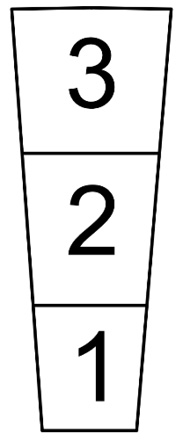
Figure 9.28 – Paper cut-out for shock cord
To install the shock cord into our model rocket, we do the following:
- Cut out the paper wedge (image may be found in the GitHub repository of this chapter specified in the Technical requirements section).
- Glue one end of the elastic cord to section 1 of the cutout (Figure 9.29 a).
- Fold section 1 onto section 2 (Figure 9.29 b).
- Put glue on section 3 and fold the mount in half (Figure 9.29 c).
- Allow to dry before gluing the mount inside the paper tube at the opposite end of the motor mount (Figure 9.29 d):

Figure 9.29 – Installing the shock cord
Ensure that the mount is placed far enough inside the paper tube so that it will not interfere with the nose cone shoulder (>20 mm).
With the shock cord installed, it is now time to glue the fin can in place on the rocket.
Installing the fin can
When we designed the fin can, we purposely gave it an internal diameter slightly larger than the outside diameter of the paper tube. This allows us to easily slide the fin can in place over the paper tube. We will secure the fin can in place with glue. White craft glue should be sufficient.
To do this, we do the following:
- Slide the fin can over the paper tube such that the fins are pointing toward the bottom of the motor mount and away from the shock cord, allowing a space between the bottom of the fin can and motor mount (Figure 9.30 a).
- Apply white glue around the paper tube in the space between the bottom of the fin can and motor mount (Figure 9.30 a). A light layer of glue should be sufficient.
- Slide the fin can over the glue, lining up the bottom of the fin can with the bottom of the paper tube (Figure 9.30 b):
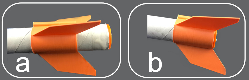
Figure 9.30 – Gluing the fin can in place
- Let the glue dry before handling.
With the fin can in place, we can now attach the nose cone and parachute and complete the construction of our model rocket.
Finishing the construction of our model rocket
To complete our model rocket, we need to tie the nose cone and parachute to the shock cord. To do so, we do the following:
- Thread the shock cord through the channel at the bottom of the nose cone and tie a knot (Figure 9.31 a).
- Thread the nose cone through the shrouds of the parachute and tie a knot (Figure 9.31 b):
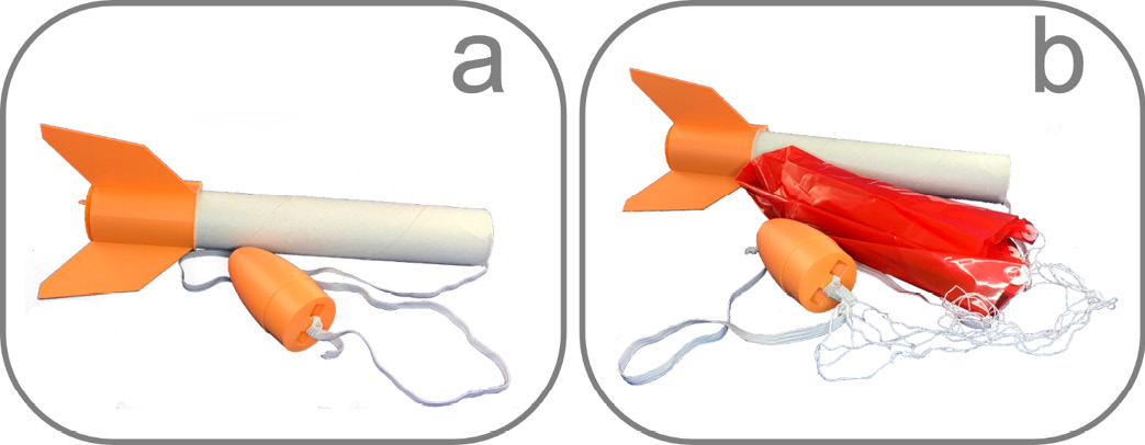
Figure 9.31 – Installing the nose cone and parachute
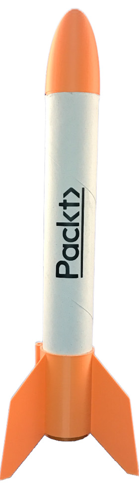
Figure 9.32 – The completed model rocket
The rocket is now complete. Here is a photo of our rocket lifting off:
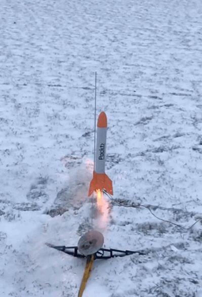
Figure 9.33 – Lift-off!
The preparation of the model rocket for flight is beyond the scope of this book. Many resources, such as YouTube, exist on how to prepare a model rocket for launch. The best resources are the instructions given from the manufacturers of model rocket launchpads and launch controllers, manufacturers such as Estes Industries (https://estesrockets.com) or Quest Aerospace (https://www.questaerospace.com).
As with any hobby that involves projectiles, it is imperative that we follow all local laws and safety precautions when engaging in model rocket flight.
Summary
In this chapter, we designed and built a model rocket using a standard paper tube from a paper towel roll. As measuring a paper tube can be challenging, we designed and printed a measurement tool to give us an accurate measurement of the internal diameter of the paper tube.
We used this measurement to design and print a motor mount that we installed and used to give us an accurate outside diameter of the paper tube. Using the internal and outside diameter measurements, we created a nose cone. We designed a fin can using the outside diameter measurement and glued it in place at the bottom of the paper tube. We then finished the construction of our model rocket with a shock cord and parachute.
Although this chapter was geared toward the design and construction of a model rocket, the key takeaway from this chapter should be the lessons learned in designing and printing parts around an existing shape – in this case, a simple paper tube.
In the next chapter, we will reflect on some of the ways in which 3D printing can shape the future, and we'll be designing and building a birdhouse.