Chapter 2: What Are Slicer Programs?
To 3D-print an object, we must first create instructions on how to do so in a language that the 3D printer understands. This language is called G-code, and to describe it in its simplest form, it is code that tells the printer head where to move and when. To create G-code, we utilize software called slicers.
In this chapter, we will create simple G-code programs before we investigate the various slicer programs in use today for 3D printing.
In this chapter, we will cover the following topics:
- Controlling a 3D printer using G-code
- Common FDM slicer programs
- Slicer programs for liquid resin 3D printers
Technical requirements
In this chapter, we will get acquainted with 3D printers. To complete the hands-on portion, we will require the following:
- A late-model 3D printer, preferably the Creality Ender 3 V2.
- A Windows, macOS, or Linux computer with a USB cable.
- The code and images for this chapter can be found here: https://github.com/PacktPublishing/Simplifying-3D-Printing-with-OpenSCAD/tree/main/Chapter2.
Controlling a 3D printer using G-code
Computer Numeric Control (CNC) is a method of controlling a machine from a computer or controller. Early CNC machines from the 1940s used punch tape and were used to crudely control machines of the time. Combining advanced computer systems with machines in the 1960s gave way to the CNC machine we know today.
3D printers are, in essence, a form of CNC machine. While CNC machines are subtractive as they chip away material to make parts, 3D printers are additive as they deposit material. G-code is the language that CNC machines and 3D printers use to communicate with their respective controllers.
In this section, we will explore G-code and use it to control our printer.
What is G-code?
So, what exactly is G-code? As mentioned, G-code is the language that 3D printers and CNC machines use for instructions. To get a more detailed understanding, let's look at how a computer communicates with a 3D printer.
Looking at Figure 2.1, we can see that the computer sends G-code commands to the 3D printer and receives sensory data back:

Figure 2.1 – Communicating with a 3D printer
Such G-code commands may be used to home the printer or set the temperature of the hot end or bed. Sensory data coming back can be the hot end temperature, the bed temperature, or an indication that one of the limit switches for an axis (x, y, and z) has been engaged.
To gain a deeper understanding of G-code, let's break down G-code commands.
Understanding G-code
G-code for a 3D printer consists of commands that start with the letter G or the letter M and control the movement and functionality of the 3D printer.
In Figure 2.2, we can see a list of G-code statements on the left. If we were to execute each statement sequentially, the print head would be positioned in the spot we see in Figure 2.2:

Figure 2.2 – G-code commands used with a 3D printer
The first statement, G28, homes the print head on all axes. The G0 Z10 command moves the print head to 10 mm above the bed. G0 X120 Y120 Z20 then moves the print head 120 mm in the x direction, 120 mm in the y direction, and 20 mm in the z direction (the position as shown in Figure 2.2).
The following are some common G-code commands:
- G0 – fast linear motion
- G01 – controlled linear motion set by an additional F parameter (for example, G1 Z15.0 F9000)
- G28 – auto home
- M104 – set the hot end temperature
- M140 – set the bed temperature
- M117 – set the LED message
- M106 – set the cooling fan speed
By stringing together G-code commands in a file, we can have our 3D printer perform tasks such as executing print jobs and bed leveling.
Using Pronterface to control our 3D printer
Pronterface is a 3D printer control and printing application written in Python. Although a little dated, it offers a simple GUI in which to control our 3D printer. To install Pronterface onto our computer, follow these steps:
- Navigate to http://www.pronterface.com.
- Click on the DOWNLOAD link.
- Find the appropriate installation file, and then download and install it (please note that the program may be referred to as Printrun).
Once installed, open up Pronterface. We can use Pronterface for either the Ender-3 V2 or the other 3D printers. To connect the computer to our printer, do the following:
- Connect the Ender-3 V2 or another 3D printer to the computer using a USB cable.
- From the Port selection at the top left, select the proper port for the printer.
- Set the baud rate to 115200 (this value may be dependent on the 3D printer).
- Click on the connect button and observe that the printer connects to the computer.
Now that we have our printer connected, let's take a short look at the GUI. Observe the control wheel at the top left-hand side of the program, as shown in Figure 2.3:
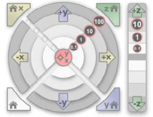
Figure 2.3 – The Pronterface control wheel
To verify that we can control our printer with Pronterface do the following:
- Click on 10 under the +Z button and observe that the print head moves up 10 mm in the z direction.
- Click on the x homing button at the top left and observe that the print head moves left and stops at the x home position.
Now that we have verified that we can control our printer using Pronterface, let's start writing some G-code. At the bottom right corner of Pronterface, observe a textbox with a button named Send beside it.
Type the following into the textbox and click on Send:
G28
Observe that the print head is moved to the home position for all axes (x, y, and z).
The G28 Command
The G28 command on its own will home all axes as we have observed. To home an axis by itself, put the axis name after G28 – for example, to home the y axis, type in G28 Y.
You may recall from Chapter 1, Getting Started with 3D Printing, how tedious manually leveling the corners of our print bed was, so let's write some G-code to assist us.
Leveling the corners with G-code
Putting our G-code knowledge to work, let's create a bed leveling program. In a text editor (such as Notepad in Windows), type in the following and save it with the filename level-bed.gcode:
G28
G0 Z20
G0 X20 Y20
M0 Position paper
G28 Z
M0 Adjust level
G0 Z20
G0 X180 Y20
M0 Position paper
G28 Z
M0 Adjust level
G0 Z20
G0 X180 Y180
M0 Position paper
G28 Z
M0 Adjust level
G0 Z20
G0 X20 Y180
M0 Position paper
G28 Z
M0 Adjust level
G0 Z20
G28
Be sure to use the .gcode extension in the filename. Before we run our program, let's look at some of the commands we have just written.
We start the program with G28, which we know homes the print head. From there, we move the print head up 20 mm (G0 Z20), then 20 mm in the x direction (G0 X20), and 20 mm in the y direction (G0 Y20).
The M0 Position Paper command creates a pause and displays the Position Paper message on the LCD screen of the printer. The printer will stay paused until we click on the control knob.
It is time to run our program in Pronterface. To complete this, follow these steps:
- From Pronterface, click on the Load file button located at the top center of the screen.
- Locate level-bed.gcode and load it by clicking Open.
- Click on the Print button at the top center of the screen.
- Observe that the print head is homed before moving to the first leveling position. We should see the Position paper message on the LCD screen. Place a piece of paper the same size as we used in Chapter 1, Getting Started with 3D Printing, under the print head.
- Click on the control knob. Observe that the print head lowers to the print bed. Observe the Adjust level message on the LCD screen.
- Referring to Figure 1.13 from Chapter 1, Getting Started with 3D Printing, adjust the nearest leveling wheel so that there is a slight tug on the paper. The paper should not rip.
- Click on the control knob to move to the next leveling point.
- Repeat until all four corners have been leveled.
Running Our Code from the 3D Printer
We actually do not need a computer connected to our 3D printer to run our level-bed.gcode program. We could just simply load it onto a microSD card and run it from the 3D printer. Running print jobs from the 3D printer itself is the most common way to run a print job, as it does not tie up a computer for hours.
Congratulations are in store, as we have just written and run our own bed leveling program using a little bit of G-code! It is now time to look at slicer programs that create G-code for our 3D printers.
Common FDM slicer programs
As we discussed in the previous section, G-code is the language used to control 3D printers. G-code controls both the movement of the print head and the extrusion of plastic from the nozzle, which allows us to create physical objects with our 3D printer.
But how do we create the G-code needed to print an object? Writing the G-code ourselves is obviously an exceedingly difficult thing to do. This is where slicers come in.
Before we explore a few slicer programs available for our FDM 3D printer, let's look at what a slicer does.
Slicing an object into G-code
A slicer is software that takes 3D object files and converts them into G-code that our 3D printer understands.
In Figure 2.4, we can see the process documented graphically:

Figure 2.4 – Converting a 3D object file into G-code
A 3D design – in this case, a riser for a computer monitor – designed in Computer-Aided Design (CAD) software is converted to a 3D object file. 3D object files are generally stored as STL, OBJ, or 3MF files, and are created using CAD software.
The slicer analyzes the 3D object file and "slices" it into layers, divided along the z axis. Each layer is a series of G-code commands for the x axis, y axis, and the extruder. The number of layers is dependent on the layer height set in the slicer software.
In Figure 2.5, we can see the first and last slices of our computer monitor riser:

Figure 2.5 – The first and last layer slices of a 3D-printed job
As our object is 90 mm tall, when it is sliced with a 0.2 mm layer height, the result is G-code with 450 different z axis values or layers. Another way to look at it would be to visualize the print head moving up 0.2 mm on every layer 450 times during printing.
As we can see, software to perform the slicing process is valuable. Let's look at the various software applications available to do this.
Slicing software applications
Many people confuse the software applications used to prepare and control a 3D printer with the slicing software itself. For example, Pronterface has functionality to prepare a 3D object file from the slicing stage to running the print job on the 3D printer. We can also control our 3D printer with Pronterface. However, for slicing functionality, Pronterface uses the program Slic3er, which itself is offered as a standalone program.
The following are three of the available software programs we can use to create the G-code that our FDM 3D printer requires.
Slic3r
As mentioned, Slic3r is used as the slicing engine in other programs such as Pronterface and Repetier-Host. As a standalone program, Slic3r is incredibly powerful, offering control over a vast number of parameters.
Slic3r is available for Windows, macOS, and Linux and can be found at www.slic3r.org. In Figure 2.6, we can see what Slic3r looks like once we open it up and load a file to be processed, with a few areas highlighted:

Figure 2.6 – The Slic3r main page
As we can see in Figure 2.6, the plater takes up the most space on the screen. A mount for a hygrometer sits on the build plate.
Slic3r is considered fast at slicing. The following are some interesting features of Slic3r:
- The default settings in the Print | Settings section make it easy to create G-code for our 3D printer. Clicking on the Export G-code button in this section creates a G-code file to load into our 3D printer. Slic3r is not used for 3D printer control.
- Slic3r can change layer heights for part of a print. For example, our print job may start with a 0.2 mm layer height and change to a 0.1 mm layer height later in the print job. This is useful in situations where the top of a print may be rounded and smaller visible layer lines are desirable.
- Another feature worth noting is the ability of Slic3r to create a series of SVG (vector) images using the Slice to SVG... option under the File menu. At one time, this functionality was one of the few ways to slice an object for SLA (Stereolithography or liquid resin printing). However, with the plethora of slicer programs for liquid resin printers today, the Slice to SVG... feature is not as useful as it once was.
ideaMaker
ideaMaker by Raise3D is an advanced slicing and 3D printer control program. Built specifically for Raise3D's brand of industrial 3D printers, ideaMaker can be used on 3D printers from other manufacturers, including the Ender-3 V2.
ideaMaker is feature-rich, giving us the ability to cut models into pieces, easily add supports (automatic and manual), and even repair models with non-manifold edges. ideaMaker also can upload a print job directly to OctoPrint, creating an efficient slicing to printing workflow.
To get a hands-on feel for ideaMaker, let's try out a few of these more distinctive features. In the following examples, we will demonstrate usage of the Free Cut, Repair, and Texture tools.
Preparing our model
Before we start, we need to install ideaMaker and load a model. To do this, follow these steps:
- To download and install ideaMaker, go to https://www.raise3d.com/ideamaker/.
- We need an object to load into ideaMaker. A quite common 3D printer test print is 3DBenchy. To download a 3DBenchy model, go to http://www.3dbenchy.com/download/.
- To load our 3DBenchy model, use the Add button at the top left of the ideaMaker screen. Our 3DBenchy will be stored as a .stl file. For models downloaded from Thingiverse, the 3DBenchy.stl file will be found in the files folder.
- Observe that our 3DBenchy model is loaded onto the center of the build area:

Figure 2.7 – The 3DBenchy model loaded into ideaMaker
Now that we have our 3DBenchy model loaded, it is time to cut it in half and repair the two halves.
Cutting our object
To cut our 3DBenchy into two parts, follow these steps:
- Select the model using the left mouse button.
- Select the Free Cut tool from the top toolbar:

Figure 2.8 – Using the Free Cut tool in ideaMaker
- Observe that we can move the cutting plane (blue rectangle) around the model using the orbit circles or by typing in values into the Cutting Plane dialog box (Figure 2.8). The Start Cut button cuts the model along the cutting plane.
- After the model is cut, we can move the top part to be flat on the bed:

Figure 2.9 – The result of using the Free Cut tool in ideaMaker
- There are now two models, and as we can see in Figure 2.9, they are invalid. Clicking on one, we see an error indicating non-manifold edges. To fix these errors, we need to click on the Repair icon at the top.
What Does Non-Manifold Mean?
We may see an error message about non-manifold edges with our objects after importing them into ideaMaker. To put it simply, non-manifold refers to shapes that cannot exist in the real world, such as a wall without a thickness. It is a good idea to fix non-manifold errors, as our 3D printer will not know how to print a part with such errors correctly.
We have successfully cut and repaired an object in ideaMaker. Now, let's look at texturing.
Applying textures in ideaMaker
One of the most exciting features in ideaMaker is the ability to add textures to an object before printing it. Adding a texture not only strengthens the object but helps in taking away the attention that layer lines have in a 3D print, as shown in the following photo:

Figure 2.10 – A non-textured part versus a textured part using ideaMaker
In Figure 2.10, we can see the effect of applying textures. The part on the left in the photo was printed without texturing, while the part on the right had a texture applied to it in ideaMaker.
As we can see, texturing adds a dramatic effect to a part. There are many textures to choose from on the ideaMaker website. Let's try some texturing ourselves. To do so, follow these steps:
- Load a new 3DBenchy object into ideaMaker (delete the objects from the previous section if they are still present).
- Select the 3DBenchy object and click on the Texture icon at the top.
- From the drop-down menu, select Custom Texture.
- Click on the More drop-down menu and select Import from ideaMaker Library. Observe that our web browser is opened, and we are taken to the textures page of the ideaMaker website.
- Select a pattern; in Figure 2.10, the Asian Wealth pattern was used. Observe that we are taken to a web page that is specific to the pattern.
- Click on the Import to ideaMaker button. Observe that a pop-up window showing the URL for the texture pops up:

Figure 2.11 – Importing a texture from the ideaMaker website
- Click on the Copy button.
- Observe that when we return to ideaMaker, we are presented with a Download Texture dialog box. Click on the Download button to download the texture.
- Click on the Next button.
- Click on the Yes button to override the texture parameters.
- Observe that our 3DBenchy object is now covered with a pattern:

Figure 2.12 – A 3DBenchy object with a texture applied
Texturing in ideaMaker only affects the sides of an object and not the top or bottom once it is sliced. Now that we have taken a brief look at ideaMaker, let's look at Cura.
Cura
At the time of writing, Cura is the most popular 3D printer slicing software. Cura is developed by the Dutch company Ultimaker and is an open source program that is available to download for free.
Being as popular as it, Cura has an extensive large third-party plugin marketplace. Plugins for such things as OctoPrint integration and OpenSCAD file support are some of the notable additions we can add to our Cura installation. Figure 2.13 is a screenshot of some of the plugins available in Cura:

Figure 2.13 – A screenshot of the Cura marketplace
In addition to the many plugins available, Cura has many features built in that can be used for slicing our objects. One such feature is tree support, which creates unique support structures that resemble the trunk of a tree.
What Are Supports in Slicing?
For many objects, there are sections that are suspended from the air and require supports built from the build plate to print them. Think of an extended arm in a model of a person. Our 3D printer would not be able to print such a thing without a support structure built from the build plate. Cura comes with two different support types, normal or tree. Each support type is designed to be easily removed after printing.
Let's get some hands-on experience with tree support by applying it to an object.
Using tree support on an object in Cura
To gain a better understanding of tree support, let's load a model and slice it. To do this, follow these steps:
- In a web browser, navigate to https://ultimaker.com/software/ultimaker-cura and install Cura.
- An object with a significant overhang demonstrates the use of tree support quite well. For this example, we will use the popular Baby Yoda model from MarVin_Miniatures on Thingiverse. Navigate to https://www.thingiverse.com/thing:4038181 and download the Baby Yoda model.
- The file we are looking for is called Baby_Yoda_v2.2.stl and is in the files folder.
- In Cura, click on File | Open File(s) and load the Baby_Yoda_v2.2.stl object:

Figure 2.14 – Baby Yoda model from Thingiverse (MarVin_Miniatures)
- To orbit in Cura, we click and hold the right mouse button while moving the mouse. If we click and hold the middle mouse button, we should be able to pan. Using these techniques, we can get an all-around view of the model.
- When first installed, Cura defaults to the basic visibility for settings. To see all the settings, click on Preferences | Configure Cura... | Settings | Check all:

Figure 2.15 – Setting visibility in Cura
- Click on Close.
- Now that we have access to all the settings, it is time to add some support to our Baby Yoda model. Click on the top-right panel to get a view of the print settings.
- Expand the Support selection and click on Generate Support:

Figure 2.16 – The Cura Support settings
- For Support Structure, choose Tree from the dropdown.
- Close Print settings by clicking on X at the top.
- Click on the blue Slice button at the bottom right-hand side of the screen.
- Observe the Slicing... message at the bottom right-hand side of the screen.
- After a short while, observe that the message box at the bottom-right has changed. Information on how long the print job will take as well as the amount of filament needed to print the object is present. A Preview button is present as well, which you should click.
- Observe a newly created tree-like support structure around the Baby Yoda model:

Figure 2.17 – Baby Yoda with tree support in Cura
We now have some hands-on experience with both ideaMaker and Cura. We can use this knowledge in the upcoming chapters as we slice and 3D-print objects.
Other programs we can use
Our list of slicer programs is by no means a complete list. The following is a list of other programs we can consider:
- PrusaSlicer is popular with Prusa-made printers. PrusaSlicer is based on Sli3r and can also be used with non-Prusa 3D printers.
- Simplify3D is one of the few 3D printer applications with a cost ($149 USD). Simplify3D boasts customizable supports, although that advantage has disappeared in the last few years.
- Skeinforge is a Python-based slicer and is considered a more complicated program to master. We can find the Skeinforge slicer engine in the Repetier-Host application.
- Creality Slicer comes with Creality 3D printers and is a version of Cura optimized for Creality 3D printers.
As we can see, there are many options we can choose from for slicing. Picking the right slicer may take some time.
Which FDM slicer should I choose?
Choosing the right slicing software for our projects may take some research. Slic3r has traditionally been at the cutting edge; however, other slicers are innovating quite quickly. At the time of writing, the popular program for slicing and preparing print jobs is Cura, although ideaMaker with its texturing abilities is starting to become more popular.
What it really comes down to is personal preference. For some of us, one application may be more intuitive than another. For the duration of this book, however, we will be mostly using Cura.
Before we delve into FDM slicers, let's expand our knowledge on slicers with a look at slicing programs for liquid resin printers.
Slicer programs for liquid resin 3D printers
As we will be working with FDM 3D printers throughout this book, we will be using FDM slicers such as ideaMaker and Cura. However, understanding that there is a whole different suite of slicers for 3D printers other than FDM 3D printers is good knowledge to have when we decide to venture beyond FDM 3D printing in the future.
Liquid resin 3D printing is a technology that has dramatically come down in cost to the point now where an entry-level liquid resin printer costs around $300 USD. So, what is liquid resin printing, and what are the software options available? We will start off by answering the first question.
What is liquid resin printing?
A liquid resin 3D printer is one where a series of images is projected onto a build plate through a clear bottom VAT (tank). This process is visualized in Figure 2.18:

Figure 2.18 – A visual representation of liquid resin printing
As we can see, the constant incremental raising and lowering of the build plate in the VAT of photosensitive liquid resin creates an object on the build plate. The set layer height determines the size of the increment. So for example, if the layer height is set to 0.05 mm then the amount the build plate increments on each cycle is 0.05 mm.
Why Use a Liquid Resin Printer?
Liquid resin printers tend to have smaller build areas than FDM printers and require Personal Protection Equipment (PPE) when handling toxic resins. Also, a curing process is required after the print is done. Despite these challenges, the detail that a liquid resin printer provides on small prints is exceptional. This makes liquid resin printers ideal for small figurines and electronic component cases.
Unlike FMD 3D printers, liquid resin printers do not handle G-code but instead slices of images. Each image represents a layer of the object and is projected onto the build plate for a few seconds. By its very nature, liquid resin printing excels at fine details, as the resolution is not determined by the diameter of a nozzle.
Let's look at a couple of the slicing programs available for liquid resin printing.
Chitubox
Chitubox is a free 3D printer slicing software program available for Windows, macOS, and Linux. Unlike many vendor-specific slicers, Chitubox produces files that can be used on many different liquid resin printers, such as the Anycubic series of liquid resin printers.
In Figure 2.19, we can see a screenshot of Chitubox. A case for a Raspberry Pi Zero sits in the build plate area:
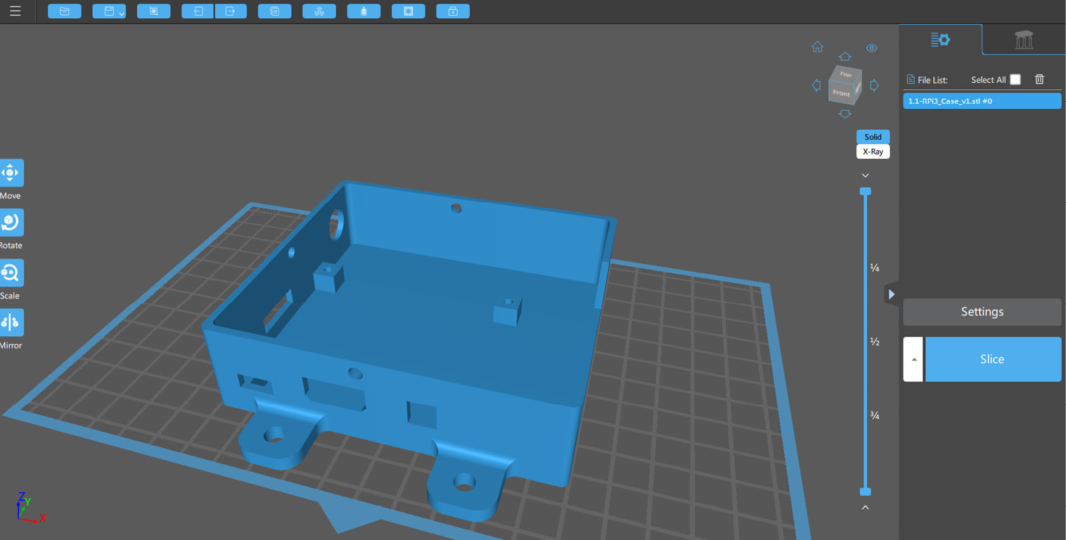
Figure 2.19 – A screenshot of Chitubox
Clicking on the Slice button brings us to a page where we can analyze each layer before creating a file for our liquid resin printer:

Figure 2.20 – The slicing page in Chitubox
We can also change properties such as Exposure Time and Lift Distance on this page. These properties as well as others are dependent on the resin and the printer used. In Figure 2.20, we can see that the print job will take 1 hour and 8 minutes, which is relatively fast.
The Anycubic Photon Workshop
Unlike Chitubox, the Anycubic Photon Workshop is designed for use by Anycubic liquid resin printers. We can see a screenshot of this program in Figure 2.21:
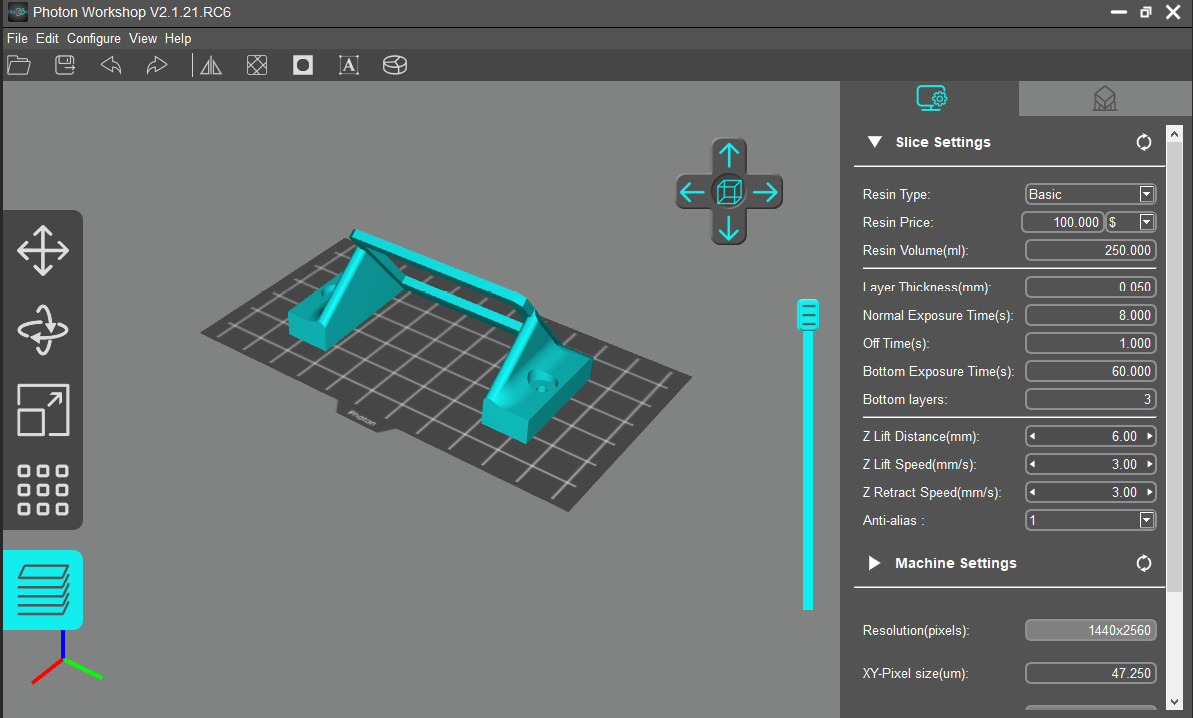
Figure 2.21 – A screenshot of the Anycubic Photon Workshop
As we can see, the slicing properties are available on the main page of the Anycubic Photon Workshop. There is also a slider that lets us view the different layers of our model. Although the Anycubic Photon Workshop does not support printers other than the Anycubic brand, the program is an excellent option for those of us with an Anycubic liquid resin printer.
Summary
In this chapter, we learned about G-code and how we can use it to control a 3D printer. Using Pronterface, we were able to control our printer through the interface as well as through executing G-code.
We were also able to create our own bed-leveling program by writing our own G-code, automating the tedious process of moving the print head around the bed.
Then, we looked at slicer programs, getting hands-on experience with ideaMaker and Cura, two enormously powerful and popular slicer programs. We finished off the chapter by taking a brief look at a couple of liquid resin slicer programs.
In the next chapter, we will take what we have learned so far and start 3D-printing physical objects.