Chapter 7: Creating a 3D-Printed Name Badge
In Part 1, Exploring 3D Printing, we covered the basics of 3D printing. We looked at the various components that make up a 3D printer and had a brief overview of the several types of materials we can print with. In Part 2, Learning OpenSCAD, we jumped into OpenSCAD by starting out with simple concepts before looking into modules and libraries. In Part 3, Projects, we will combine what we learned from the first two parts of the book and go from OpenSCAD design to 3D-printed objects.
Part 3, Projects, starts with this chapter, where we will create a 3D-printed name badge to be worn at conventions or inside shops. We will design the name badge in OpenSCAD before importing our design into a slicer program. We will then proceed to print out our design.
In this chapter, we will cover the following topics:
- Creating text for our 3D-printed name badge
- Adding a base plate to our 3D-printed name badge
- Printing out our 3D-printed name badge
Technical requirements
The following is required to complete the chapter:
- Any late-model Windows, macOS, or Linux computer that can install OpenSCAD and Cura.
- 3D printer—any fused deposition modeling (FDM) printer should work; however, the Creality Ender 3 V2 is the printer used for our example.
- Epoxy glue.
- Brooch bar pin, as depicted in the following picture, for attaching our 3D-printed name badge to a shirt or jacket:

Figure 7.1 – Brooch bar pin
The code and images for this chapter can be found here:
https://github.com/PacktPublishing/Simplifying-3D-Printing-with-OpenSCAD/tree/main/Chapter7
Creating text for our 3D-printed name badge
In Chapter 5, Using Advanced Operations of OpenSCAD, we extruded text for our Thumbs Up Award design. Our focus was on creating a dynamic backing plate based on the size of the text, thus we limited our exposure of OpenSCAD's text operation to a monospaced font with default alignment and size settings.
In this section, we will look more closely at the text operation and at ways that would make our text curve around shapes. Let's start by taking a closer look at the text operation.
Understanding the OpenSCAD text operation
At the time of writing, the OpenSCAD text operation has 10 parameters that can be set. These include parameters for font, vertical and horizontal alignment, as well as the size of text and the spacing between letters. A full list of these parameters can be found here: https://en.wikibooks.org/wiki/OpenSCAD_User_Manual/Text.
In this section, we will look at using a specialized font, letter spacing, font size, and text direction.
Using a specialized font
Specialized fonts give us the opportunity to add a little something extra to our designs. We may find many such fonts installed on our computer already; however, an interesting font that many of us may not have installed is the Nasalization font made by Raymond Larabie.
As its name implies, the Nasalization font is a set of characters that resemble the National Aeronautics and Space Administration (NASA) "worm" logo from the 1970s. In this section, we will download the font and test it out in OpenSCAD.
The Worm versus the Meatball
The original NASA logo featured two planets and a red chevron and was affectionately called the "meatball" logo. Considered too cluttered by the 1970s (and with a little push from a Nixon-era design improvement program), a more simplified "worm" logo was developed. However, not everyone at NASA liked the new design, and thus it was retired in 1992. The "worm", however, made a comeback and was featured in a SpaceX Falcon 9 launch.
We will start by downloading and unzipping the font, as follows:
- Navigate to the following website and click on the Download link on the right-hand side: https://www.dafont.com/nasalization.font.
- We will install the font in our OpenSCAD libraries folder. In OpenSCAD, click on File | Show Library Folder... to open the OpenSCAD libraries folder.
- Create a new folder inside the libraries folder and call it fonts.
- Unzip the nasalization.zip file.
- Copy the nasalization-rg.otf file into the fonts folder.
- Create a new OpenSCAD file and type the following code into the editor:
use <fonts/nasalization-rg.otf>
text("NASA", spacing=1.5, font="Nasalization:style=Regular");
What we are doing here is loading the Nasalization font into our program with the use command. We then create text using the text operation, deploying the Nasalization font with a Regular style. We also set spacing to 1.5 to give our design a less cluttered look.
- Click on Preview or hit F5 on the keyboard. Observe here that we have recreated the NASA "worm" logo:

Figure 7.2 – NASA "worm" logo made with Nasalization font and OpenSCAD
Now that we know how to add a specialized font to OpenSCAD, let's investigate a few text attributes we may modify.
Changing the size and direction of text
A couple more parameters that we can modify with the text operation include the size and direction parameters. As their names imply, size controls the size of the text, and direction controls the direction.
Let's explore these parameters by doing the following:
- Modify the code so that it looks like this:
use <fonts/nasalization-rg.otf>
text("NASA", direction="ttb", size=100, font="Nasalization:style=Regular");
Let's start with direction. The values we may choose for direction are the default ltr (left-to-right), rtl (right-to-left), ttb (top-to-bottom), and btt (bottom-to-top). We are setting this value to ttb, which will create vertical text. We are also setting size to 100, which is 10 times the default.
- Click on Preview or hit F5 on the keyboard. Observe here that the direction of the text, as well as its size, has changed:

Figure 7.3 – Vertical NASA "worm" logo made with Nasalization font and OpenSCAD
Now that we have a better understanding of the text operation, let's look at how we can curve text in OpenSCAD.
Making text curve in OpenSCAD
Bending or curving text in an arch is a common effect used in design. Bending or curving text may be used to draw attention to a part of our design, such as a name. In this section, we will create a module to bend text in a circular pattern. We will start off by learning how to analyze each letter in a text string.
Finding the first letter in a string
For text strings in OpenSCAD, we can access each letter using an index. We use open and closed square brackets to indicate an index. To test this out, do the following:
- Create a new OpenSCAD file and type in the following code:
test_text = "Hello OpenSCAD";
echo(test_text[0]);
As with many programming languages, OpenSCAD uses zero as the first index position. With our code, we are creating a string called Hello OpenSCAD and are echoing out the first letter using the [0] index.
- Click on Preview or hit F5 on the keyboard. Observe here that the letter H is shown in the console:
Figure 7.4 – The first letter of "Hello OpenSCAD" echoed in the console
Now that we understand how to find an individual letter from a text string in OpenSCAD, let's now explore how to iterate so that we can cycle through the text.
Using a for loop to cycle through text
As with many programming languages, OpenSCAD offers functionality for iteration in the form of a for loop. Using a for loop, we can cycle through the letters of a text string. Let's learn how to do this with a simple example, as follows:
- Create a new OpenSCAD file and type in the following code:
test_text = "Hello OpenSCAD";
for(i=[0:len(test_text)-1])
{
echo(test_text[i]);
}
Before we run this code, let's examine it closely. We start off by creating a string called test_text and setting it to the value Hello OpenSCAD. In the next line, we set a for loop to count from 0 to a value equal to the length of the test_text string minus 1 and assign this value to the i variable for every iteration through the loop. For our example, the iteration would happen 14 times. In the loop, we use echo to print the letter at the i position of test_text to the console.
- Click on Preview or hit F5 on the keyboard. Observe that each letter of test_text is printed out one by one in the console:
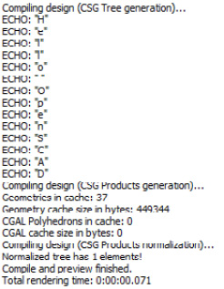
Figure 7.5 – Letters echoed to the console
Why Do We Subtract 1 from the Length of test_text?
With many programming languages, when iterating through a list or string, we start at index 0 and stop at the value that is one less than the length. We do this using a less-than (<) operator in the for statement. This makes sense with zero-based indexes as the value of the length of an array or string—or, in our case, the number of characters in the text—is not the same as the last index value. This is due to us starting at 0 for the first index and not 1. With OpenSCAD, we do not have the option of using a less-than (<) operator in our for loop. Thus, we must subtract 1 from the length of test_text so that we can stop our iteration on the last letter of test_text.
Now that we understand how to iterate through a string of text in OpenSCAD, let's move on to rotating the text by positioning each letter individually. We will create a module to do just that.
Creating a rotate_text() module
To rotate a string of text in OpenSCAD, we will create a module to position each character based on the parameters we pass in. We will name the new module rotate_text() and experiment with the parameters before creating a text section for our name badge.
Let's get started, as follows:
- Create a new OpenSCAD file and type in the following code:
module rotate_text(display_text,
text_size=10,
distance=20,
rotation_value=360,
tilt=0)
{
rotate([0,0,tilt])
for(i=[0:len(display_text)-1])
{
rotate([0,0,- i*rotation_value/
len(display_text)])
translate([0,distance,0])
text(display_text[i],
font="Impact:style=Regular",
size=text_size,
halign="center");
}
}
This module takes in five parameters, with four having default values. We will start our analysis of the rotate_text() module by passing in only the first parameter.
What we are doing here is passing the HelloOpenSCAD string into rotate_text() for the value of display_text. We are leaving the other four parameters at their default settings. We leave out spacing in our string to create the desired effect.
- Click on Preview or hit F5 on the keyboard. Observe here the circle of text created:
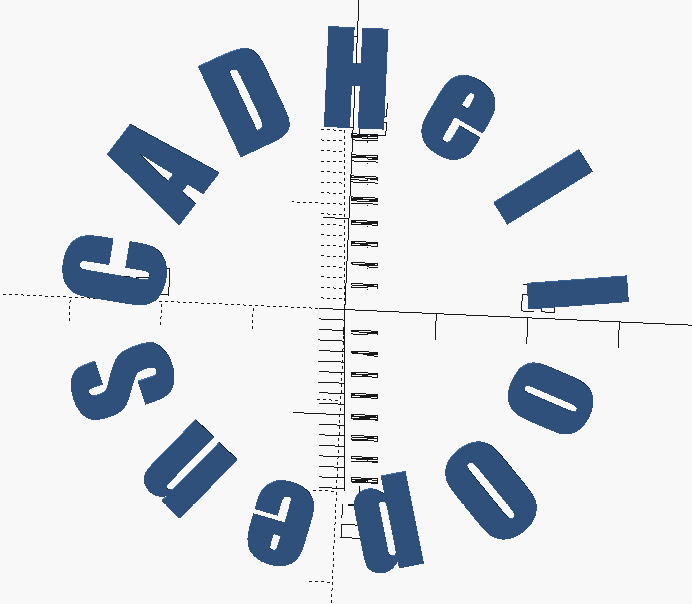
Figure 7.6 – Circle of text created using the rotate_text() module
Our code uses the Impact font, which should be found on most operating systems (feel free to use the Nasalization font from the previous section). As we can see, using default parameters gives us a circle of text, which starts at the zero position of the y axis. To fully utilize the rotate_text() module, let's look at the text_size, distance, rotation_value, and tilt parameters.
Modifying the default parameters in the rotate_text() module
By modifying the default parameters, we can create many different designs with the rotate_text() module. We will start by modifying the distance parameter. To do this, we proceed as follows:
- Modify the code that calls rotate_text() so that it looks like this:
rotate_text("HelloOpenSCAD", distance=60);
The distance parameter sets the distance from the center and, thus, the radius of the invisible circle that the text is wrapped around. With the value of 60, we triple the size of the default parameter.

Figure 7.7 – Modifying the distance property for rotate_text()
- We will now modify the text_size parameter to change the size of the text. Modify the code so that it looks like this:
rotate_text("HelloOpenSCAD", text_size=15, distance=60);
- Click on Preview or hit F5 on the keyboard. Observe here that the text is larger:

Figure 7.8 – Modifying the text_size property for rotate_text()
- The rotation_value parameter defaults to 360, which creates a full circle of text. Changing this value to anything less than 360 will create an arch instead of a circle. Modify the code so that it looks like this:
rotate_text("HelloOpenSCAD", 15, 60, 180);
We can take away the parameter names as we are setting the parameters in order. The value of 180 should create a half-circle arch of our text.
- Click on Preview or hit F5 on the keyboard. Observe here that we have indeed created a half-circle arch of our text:
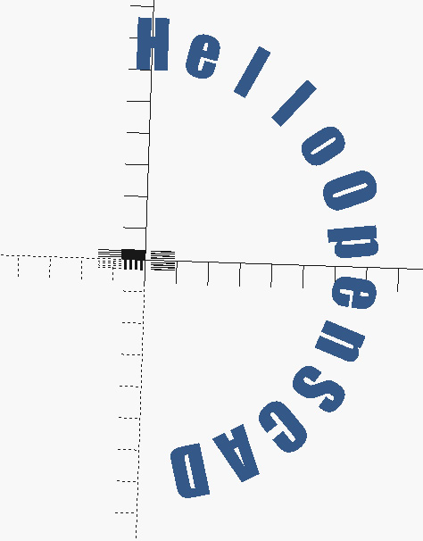
Figure 7.9 – Arch of text using the rotate_text() module
- The final parameter is tilt. This parameter sets the starting point of our text and defaults to 0, which is the 0 value on the x axis. Modify the code to add the tilt parameter, as follows:
rotate_text("HelloOpenSCAD", 15, 60, 180, 83);
The value of 83 was determined by trial and error. This value may be different depending on the font and other factors.
- Click on Preview or hit F5 on the keyboard. Observe here that our arch of text has been rotated to the left:
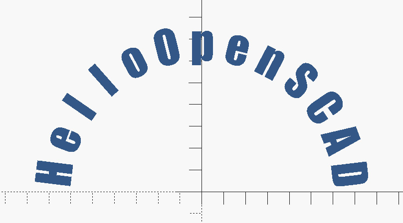
Figure 7.10 – Arch of text rotated
Now that we have a module for rotating text, it's time to put it to use to create arched text for our 3D-printed name badge project.
Creating a name tag text generator module
In this section, we will create the text portion of the 3D-printed name badge with the company name Packt Pub (shameless plug). We will create a new module to do this by doing the following:
- Using the code from the Making text curve in OpenSCAD section, add the following module after the rotate_text() module:
module create_packt_name_tag_text(
name,
name_size=20,
scale_factor=1)
{
scale([scale_factor,
scale_factor,
scale_factor])
union()
{
rotate_text("PACKT", 10, 30, 75, 30);
rotate_text("PUB", 10, -40, -75, -23);
text(name, size=name_size,
font="Impact:style=Regular",
halign="center",
valign="center");
}
}
What this code does is create the text part of a name tag for the company Packt Pub. The word PACKT is rotated over the top of the name. The word PUB is rotated below the name by virtue of a negative value for distance, rotational value, and tilt in the call to the rotate_text() module.
- Before we can run this module, we must make a call to it in our code. Delete all non-module code (code that sits outside of modules) and type in the following code:
create_packt_name_tag_text("Bob Writer");
The create_packt_name_tag_text() module takes in three parameters—the name value to be displayed, the size of the text of the name (name_size), and a scale factor (scale_factor) to adjust the overall size of the name tag text. As name_size and scale_factor have default values, we only need to pass in the name parameter. We are passing in the name Bob Writer. Feel free to pass in your own name.
- Click on Preview or hit F5 on the keyboard. Observe the following:
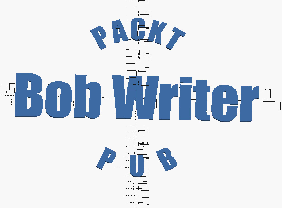
Figure 7.11 – Packt Pub name badge text
You might have noticed that the name Bob Writer is perfectly centered with the arched text on the top and bottom. This is due to the setting of halign (horizontal alignment) and valign (vertical alignment) to center. Parameters for rotate_text() and font may be modified to achieve the desired effect.
- As we will be using this code to build our 3D-printed name badge, we should save it to our OpenSCAD libraries folder. Click on File | Save As ... and save the file as name-badge-text.scad in the OpenSCAD libraries folder (File | Show Library Folder...).
Creating customized text is the first part of making our 3D-printed name badge. As we can see, with a few simple modules, we are able to bend text to make our design more appealing. The parameter values used have been derived by trial and error. By parametrizing our code, we can make modifications to suit any company or employee name.
In the next section, we will move on to creating a base for our 3D-printed name badge.
Adding a base plate to our 3D-printed name badge
To complete our 3D-printed name badge, we require a base plate for the text. We will start with a basic shape before we implement the code to build a base plate with a series of modules. We will then add our text to complete the design of the 3D-printed name badge. Let's start with a module to create a basic 2D shape.
Creating our first shape
We will start off the design of our base plate with a simple 2D design. As with the code we covered in the Creating our PVC pipe hook section of Chapter 4, Getting Started with OpenSCAD, we take the intersection of a circle and square to give us a basic first shape. We will put this code inside a module. Let's get started, as follows:
- Create a new OpenSCAD file and type in the following code:
module create_first_shape()
{
intersection()
{
translate([20,0])
circle(d=85);
translate([30,0])
square([60, 70],center=true);
}
}
create_first_shape();
The code to create our first shape is wrapped up in the create_first_shape() module. The translate values push the shape to one side of the x axis. The values used to define the diameter of the circle and the size of the square may be modified to create a desired effect. The module is called with this line of code: create_first_shape();.
- Click on Preview or hit F5 on the keyboard. Observe here that a basic shape is created:

Figure 7.12 – Shape created from the create_first_shape() module
As we can see, our first shape sits on one side of the x axis. This sets up the shape to be mirrored later. Before we do that, we will create a module to represent the brooch pin for our 3D-printed name badge. Let's get started.
Adding an indent for the brooch pin
As we will be gluing the brooch pin to the back of the plate, a good thing to assist us is an indent or a pocket in which we can set the pin. A 1 mm indent on the back of the 3D-printed name badge should be sufficient to help us position and glue the brooch pin in place. We will create a module to do this.
Due to the different sizes of brooch pins, we will accept parameters in our module. For the brooch pin shown in Figure 7.1, the width is 32 mm and the height is 5 mm. Let's start by adding code for the new module, as follows:
- Below the create_first_shape() module, add the following code:
module create_brooch_indent(width, height)
{
translate([0,0,-1])
color("#dc143c")
linear_extrude(2)
square([width, height], center=true);
}
With this code, we create a module called create_brooch_indent(), in which we take in width and height parameters. We use these parameters to create a square, which is extruded to 2 mm, colored red (#dc143c), and moved down in the z axis by 1 mm. We add color to highlight the indented region and move it down 1 mm to get a clean cut. Please note that color added to a shape only shows up in preview mode (F5).
- Comment out the create_first_shape(); code and add the following code:
create_brooch_indent(32, 5);
We are calling the create_brooch_indent() module with the values of 32 mm for the width value and 5 mm for the height value.
- Click on Preview or hit F5 on the keyboard. Observe here that a red shape representing the brooch pin is created:
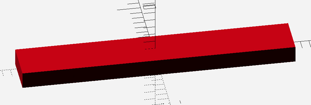
Figure 7.13 – Brooch pin indent shape
With the create_first_shape() and create_brooch_indent() modules written, it's now time to create a module that will put all the code we've written together, to make the base plate for our 3D-printed nameplate.
Putting the first shape and indent together
We will start by wrapping the create_first_shape() and create_brooch_indent() modules in a new module called create_base_plate(). We will then combine the name tag text with the base plate to finish our design before exporting it to a .stl file for 3D printing.
Coding the create_base_plate() module
We will code the create_base_plate() module using the create_first_shape() and create_brooch_indent() modules. With this new module, we will have all the code needed to create a base plate for our 3D-printed name badge. To create the create_base_plate() module, we do the following:
- Below the create_brooch_indent() module, add the following code:
module create_base_plate(
thickness,
scale_factor=1)
{
difference()
{
linear_extrude(thickness)
scale([scale_factor,
scale_factor,
scale_factor])
union()
{
create_first_shape();
mirror([1,0,0])create_first_shape();
circle(d=90);
}
create_brooch_indent(32, 5);
}
}
At the heart of the create_base_plate() module is the union of two calls—the first one is to the create_first_shape() module, with the second one modified by a mirror operation. A circle with a diameter of 90 is added. A scale operation controls the size of the base plate. Of note is the absence of the create_brooch_indent() module from the scale operation as the size of the brooch pin is a set size.
- To call the create_base_plate() module, remove all non-module related code and add the following code:
create_base_plate(2.5, 0.7);
The create_base_plate() module takes in two parameters—thickness (thickness of the base plate) and scale_factor. We pass in a value of 2.5 for the thickness parameter, and even though scale_factor has a default parameter of 1, we pass in a value of 0.7 to make the ratio of the base plate to the brooch pin smaller.
- Click on Preview or hit F5 on the keyboard. Rotate the resulting shape to view the indent for the brooch pin, as illustrated here:

Figure 7.14 – Base plate with brooch pin indent
- As we did with the name-badge-text.scad file, we will add this code to our library. Click on File | Save As ... and save the file as base-plate.scad in the OpenSCAD libraries folder (File | Show Library Folder...).
With our base plate code saved to the OpenSCAD libraries folder, creating our 3D-printed name badge simply involves importing name-badge-text.scad and base-plate.scad into a new file and utilizing the modules these files provide us.
Let's do that now.
Combining the text with the base plate
To finalize our design, we will create a new file and import the libraries for generating the name tag text and the base plate. To do this, we proceed as follows:
- Create a new OpenSCAD file and type in the following code:
use<base-plate.scad>
use<name-badge-text.scad>
color("blue")
create_base_plate(2.5, 0.7);
color("gold")
translate([0,0,2])
linear_extrude(2)
create_packt_name_tag_text("Bob Writer",
scale_factor = 0.65);
In our code, we import the libraries to create a base plate and name tag text with the use keyword. We then create a base plate with a thickness of 2.5 mm and at a scale of 70%. The base plate is colored blue for effect. We then create a Packt Pub name tag using the create_packt_name_tag_text() module for the name Bob Writer, at a scale of 65%. Notice how we must specify the parameter name for scale_factor as we are not listing the parameters in order. The text is colored gold for effect, moved up 2 mm in the z direction, and extruded to 2 mm. If we did not move the text up, then the brooch pin indent would be covered up.
- Click on Preview or hit F5 on the keyboard. Observe here that a Packt Pub name badge is displayed for the name Bob Writer:

Figure 7.15 – Packt Pub name badge for Bob Writer
With the design finalized, it's now time to export it to a .stl file to be used for 3D printing.
Creating a file for 3D printing
In this chapter, we have been previewing instead of rendering while creating our design. To export our design as a .stl file, we need to render it. To do so, proceed as follows:
- Click on Render or hit F6 on the keyboard. Observe here that after a short bit of time, our design is rendered and is in one color:

Figure 7.16 – Rendered Packt Pub name badge for Bob Writer
- To make use of our design in a slicer, we will export it as a .stl file. Click on File | Export | Export as STL… or hit F7 on the keyboard. Give the file a name and save it to a location to be accessed by the slicer program.
It's now time to 3D print our design. To do so, we will load the .stl file into Cura and adjust the settings accordingly.
Printing out our 3D-printed name badge
To print out our design, we will open the .stl file in Cura and adjust the settings accordingly. We will consider the material, the bed adhesion, and other settings. We will then generate G-code for the print job before we store it on a microSD card and load it into our Ender 3 V2 3D printer.
We will start with loading our design and configuring the settings in Cura.
Preparing our design for a print job
We will print our name badge with two distinct colors as we want the name to stand out. This will require us to pause the print job and change out one color of polylactic acid (PLA) for another. We will use support for the brooch pin indent (pocket).
Before we can do all that, however, we need to load our .stl file into Cura. Let's do just that.
Loading a file into Cura
Loading a file into Cura is simple. Cura supports many different file formats, including .jpg and .png, for creating 3D prints from pictures. What we are interested in is the .stl file created from our design. To open our .stl file in Cura, we do the following:
- In Cura, click on File | Open File(s)... from the top menu.
- Navigate to the folder where the .stl file from our design is stored and click on the Open button.
Observe here that our design sits centered on the build plate in Cura:
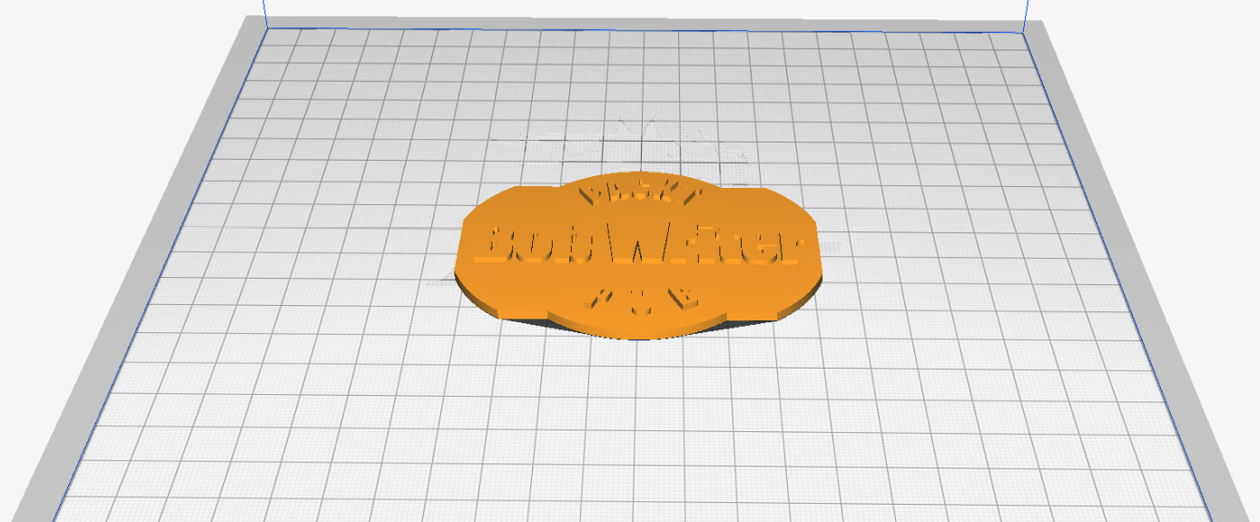
Figure 7.17 – Name badge design loaded into Cura
Now that we have our design loaded into Cura, it's time to modify the settings. We will start by loading a default slicer profile.
Using default profiles
For our projects, we will start with default templates for our slicer settings and then make modifications as needed. To select the default PLA setting in Cura, do the following:
- In the top-middle section of the screen, click on the drop-down arrow to expand the dialog, as illustrated in the following screenshot:
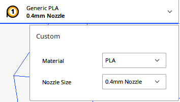
Figure 7.18 – Selecting generic slicer templates
- For Material, click on the drop-down arrow and select Generic | PLA.
- For Nozzle Size, select 0.4mm Nozzle.
Now that we have the default slicer settings in place, it's time to modify them to our needs. We will start with temperatures.
Setting temperatures
The settings to control both the nozzle and bed temperatures in Cura sit under the Material tab. Getting the temperature settings right for the material we use can be a challenge. PLA melts at a lower temperature than Acrylonitrile Butadiene Styrene (ABS) and Polyethylene Terephthalate Glycol (PETG) but the temperature may vary between manufacturers (for information on the various materials for 3D printing, please refer to the Materials available for 3D printing section of Chapter 1, Getting Started with 3D Printing). Sticking with the same brand of filament is a good practice. We will be using two distinct colors of PLA from the same manufacturer in our example.
To set temperatures, we do the following:
- Click on the down arrow on the top right of the screen to display the Print settings.
- Expand the Material section by clicking on the down arrow of the section.
- Set the temperatures to the following values:

Figure 7.19 – Temperature settings for the Material section
These settings may be modified based on the brand of PLA used. Generally, good quality can be achieved by keeping the temperature of the nozzle at the lower end to avoid the melted look that high nozzle temperatures may cause. However, care must be taken that the temperature is not too low so as to cause a jam.
For our example, our hot end uses the Polytetrafluoroethylene (PTFE) tube-to-nozzle design that comes standard with the Creality Ender 3 V2. This design works well for our purposes as PLA tends to jam when the PTFE tube does not extend directly to the nozzle. (Refer to the Upgrading the Ender 3 section of Chapter 1, Getting Started with 3D Printing for more information on PTFE tube-to-nozzle design). For PTFE tube-to-nozzle designs, it is a good practice to keep temperatures on the lower side to avoid melting the PTFE tube, which generally melts at the 230°C mark. Not only does a melted PTFE tube cause jams, but it may also release hazardous toxic fumes. Our nozzle temperature of 190°C allows us to avoid such issues.
We set the bed temperature to 60°C. This should be sufficient to hold the PLA on the build plate. A too-high bed temperature softens PLA and may make removing any support material from our print difficult.
With the temperatures set, it's time to add the support.
Adding support material to our print job
The indent or pocket we use for the brooch pin of our design requires support material. This is due to the layout of our object on the build plate. Although we could get away without support material, the indent would not be as clean as it could be, thus making it harder to slot the brooch pin into place.
To add support material to our print job, we do the following:
- Click on the down arrow on the top right of the screen to display the Print settings.
- Expand the Support section by clicking on the down arrow of the section.
- Check the Generate Support checkbox and select Normal for Support Structure, as illustrated in the following screenshot:
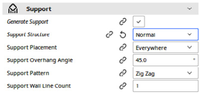
Figure 7.20 – Support section settings
Leave all the other settings at their defaults.
With support settings taken care of, it's time to move to the settings that will determine how our print sticks to the build plate during printing.
Adjusting the Build Plate Adhesion settings
One of the hardest things to get right with 3D printing is bed (build plate) adhesion or getting the prints to stick to the bed when we need them to stick and have them come off the bed when we need to remove them. Bed temperature is arguably the biggest factor in bed adhesion. Even though PLA may stick to the bed at room temperature, bringing up the bed temperature softens the PLA, which creates more adhesion.
Another factor that affects bed adhesion is the Build Plate Adhesion settings. The settings available with Build Plate Adhesion are Skirt, Brim, Raft, and None, with all settings except for None using extra filament. Ideally, we would only need to use the None setting, as the filament would extrude perfectly at the start of the print job and our print would stick to the build plate as we need it to.
Having the filament extrude a little bit through the nozzle before printing our object is a good practice, as any filament stuck to the nozzle from a previous print will be deposited on the build plate before printing the object. Also, freshly loaded filament may require a bit of extrusion before flowing nicely through the nozzle prior to printing the object. Extruding filament before printing an object "primes" the nozzle, giving the extrusion a running start. All the settings except for None may be used for this.
For more information on Build Plate Adhesion settings, refer to the Build Plate Adhesion settings section of Chapter 3, Printing Our First Object.
For our print, we will use Skirt, as we want a good flow for the extrusion but do not require extra surface area on the build plate that Raft and Brim provide due to the shape of our object (short and flat).
To set Build Plate Adhesion, do the following:
- Expand the Build Plate Adhesion section by clicking on the down arrow of the section.
- Set Build Plate Adhesion Type to Skirt, as illustrated in the following screenshot, and leave the other values at their default settings:
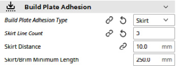
Figure 7.21 – Build Plate Adhesion settings
With our Build Plate Adhesion settings out of the way, it's time to look at postprocessing. With postprocessing, we will be able to pause our print so that we can swap out the filament for one of a different color.
Adding Pause at height postprocessing
Post-processing allows us to modify G-code generated for our print job. Functionality such as triggering a camera for time-lapse pictures may be implemented using postprocessing. For our purposes, we will use postprocessing to pause our print job so that we can change the filament for one with a different color. This will give us a 3D-printed name badge with text that is a different color than the base plate.
To set Pause at height postprocessing, we do the following:
- Click on Extensions | Post Processing | Modify G-Code to access the Post Processing Plugin page.
- Click on the Add a script button.
- Select Pause at height from the list.
- Set the values to the following:

Figure 7.22 – Pause at height settings
With these settings, the print job will stop at the height of 3 mm, where the print head is then parked at 190 mm in the x direction and 190 mm in the y direction. The nozzle temperature is set to 200°C. We add 10 degrees to soften up the PLA a little bit further for easier removal.
We will now turn our attention to slicing our object into G-code and storing it onto a microSD card to run on our printer.
Slicing our object
With our object loaded, our settings modified, and our postprocessing inserted, it's time to slice our object and store the G-code generated onto a microSD card.
To do this, we do the following:
- Insert a microSD card into the slot on the computer. A USB or SD to microSD adapter may be required.
- In Cura, observe the Slice button at the bottom-right side of the screen. The box to the left with 1 circled in red in the following screenshot indicates we are running one postprocessing event. Click on the Slice button:
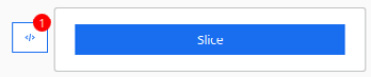
Figure 7.23 – Cura Slice button
- Observe that the time for the print job and the amount of material needed are displayed. As well, observe in the following screenshot that the Slice button turns into a button where we can select the location to store the G-code generated. Select Save to Removable... to save the G-code to the microSD card:
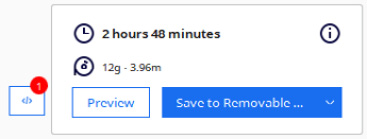
Figure 7.24 – Print job statistics and button to save G-code to microSD card
With the G-code saved onto the microSD card, it's now time to print out our object. Refer to Chapter 3, Printing Our First Object to go through the steps to do this.
Printing and finishing
The print job will run until the z axis reaches 3 mm, as set up in the postprocessing. When it reaches this point, we do the following:
- Observe that the print job is paused, and a message indicating such is displayed on the screen.
- Observe that the print head has moved to the top right of the build plate and the temperature of the nozzle is 200°C. For our example here, we use a polyetherimide (PEI) build plate:
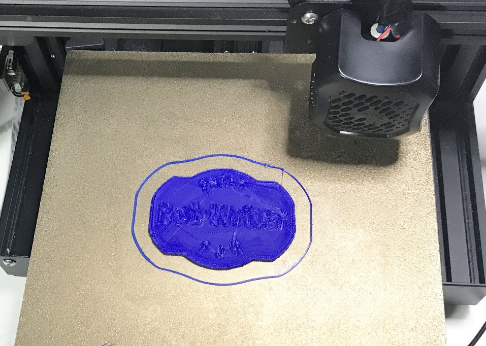
Figure 7.25 – Paused print
- Using Chapter 3, Printing Our First Object as a reference, change the filament to a filament of a different color.
- Click on the control knob to continue the print.
After the print job has finished, observe that our name badge has been created, with the letters having a different color than the base plate, as illustrated in the following picture:
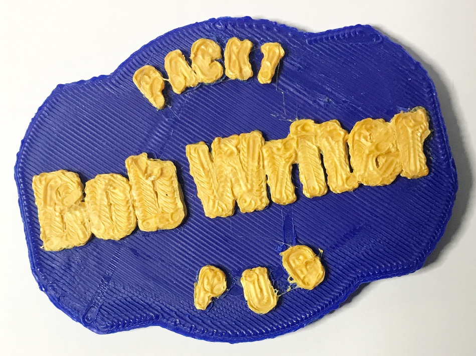
Figure 7.26 – Finished print
As we can see, the clarity of the letters leaves much to be desired. This may be improved by using a 0.2 mm nozzle as opposed to a 0.4 mm nozzle. Our settings in Cura would have to change to reflect this.
There is one thing left to do to complete our 3D-printed name badge, and that is to add a brooch pin to the back. This can be done easily using epoxy glue, as shown here:
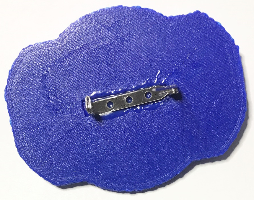
Figure 7.27 – Completed 3D-printed name badge
We have created our first OpenSCAD designed object. Now that we have this experience behind us, in the next chapters, we will implement a little more complexity in our designs.
Summary
We started this chapter by looking more closely at the OpenSCAD text operation. We learned how to install and use a customized font as we recreated the NASA "worm" logo. From there, we explored how to change the size and direction of our text.
We implemented a for loop to cycle through custom text so that we could curve it around an invisible circle. We created a specialized module to do this.
From there, we created code to make a customized 3D-printed name badge using the curved text module and a module to create a base plate from a simple 2D design. We accounted for a brooch pin by providing an indent at the back of our name badge.
We proceeded to use Cura to slice our design into G-code, which we loaded onto our 3D printer. This G-code produced a print job with a pause, to allow us to change the color of the PLA for effect.
In the coming chapters, we will expand our knowledge of 3D design in OpenSCAD further as we build more complex objects. We will build a stand for a laptop in the next chapter.