CHAPTER 12
Guitar Preamplifiers
Electric Guitar Technology
The standard electric guitar technology uses the vibrations of a ferromagnetic string to modulate the magnetic field seen by the pickup windings. The field is only being modulated by a relatively narrow wire, and so the overall change in field is small. It is therefore necessary to use pick-up coils with a large number of turns to get a usable output voltage. This means the pickup has a large amount of inductance and a significant amount of series resistance, because thin wire has to be used to physically fit in enough turns.
Electric guitars commonly have two or three pickups. In the case of three, one will be mounted just below the neck, one in the middle of the body, and one near the bridge. Guitars with four pickups are rarer but certainly exist, and there is at least one around with five pickups [1], though that is a result of modification. I could not locate one with six pickups; it would be hard to find space on the guitar body. The internal wiring of the guitar usually allows pickups to be selected, joined together, or operated in anti-phase. There is more on this in what follows.
Guitar Pickups
Pickups come in different types:
- The standard pickup has a single coil surrounding the magnetic pole-pieces. It is sometimes called a normal pickup. [2]
- The humbucking pickup [3] discriminates against ambient hum fields. The standard pickup is rather susceptible to magnetic fields, as, after all, that is what it is meant to be. However, it responds not only to the magnetic signals created by the strings but also external magnetic fields, which in practical terms means mains hum and buzz. Humbucking pickups have two windings, usually wired in series, placed around magnetic poles that alternate in polarity. The two coils are then connected in a phase relationship so that small-scale magnetic signals from the strings are reinforced, but large-scale disturbances, such as the ambient mains field in a room, affect both coils equally and are (to a first approximation) cancelled out. There are several ways to construct humbucking pickups [4], but in each the principle is the same.
There are also several ways in which a humbucking pickup can be connected; normally the two halves are simply connected in series. Figure 12.1 shows two more popular options. Figure 12.1a is the split-coil approach, where a “coil-cut” switch shorts out one half of the pickup. This is claimed to give a brighter sound, but of course the signal output is halved and the hum-cancelling feature entirely lost. Figure 12.1b is the series/parallel configuration; the parallel setting gives less output but a brighter tone. This time the hum-cancelling feature is retained.

- The third major category is the hexaphonic pickup, which has a separate magnet pole and coil for each string. It is hexaphonic because your standard (non-bass) guitar has six strings. It is also called a polyphonic pickup or (in Japan) a divided pickup and is typically used with a guitar synthesiser, in which the notes played are interpreted into MIDI commands, a process that is obviously much simpler if you have access to each string separately but is still a nontrivial task.
Alternatively, the six outputs can be processed separately in purely analogue ways. Putting them through six separate fuzz circuits gives the hexfuzz effect, which sounds very different from the standard distort-the-lot fuzz effect. Here is an example [5] using a Roland GR-100 guitar synth to create the effect. (An earlier model than the GR-700 mentioned later, released in 1981.)
I am the proud owner of a Roland G707 guitar/synth-controller (in piano black) that has two normal humbucking pickups plus a hexaphonic pickup right down next to the bridge. The hex pickup was to drive the Roland GR-700 guitar synthesizer [6] via a 24-pin connector and multi-core cable. Both were released in 1984. The humbucking pickups are loaded with 100 kΩ plus the usual guitar tone controls. The hexaphonic pickups are much more heavily loaded with 4k7 load resistors, presumably because a good high-frequency response is unnecessary for determining the fundamental vibration rate of the string. The hexaphonic signals are then applied to a series-feedback amplifier with a preset-adjustable gain of between +17 dB and +31 dB. The opamp outputs are then sent straight down the multi-core without any isolating resistors to fend off the effects of cable capacitance.
Pickup Characteristics
Both standard and humbucking guitar pickups have several thousands of turns in the coil to get an adequate output, which also means a substantial series inductance. Typical values range from 1 H to 10 H; there are many variations in design. Compare this with a moving-magnet (MM) phono cartridge, which will have an inductance almost always in the limited range of 400 to 700 mH, while a moving-coil phono cartridge has negligible inductance. For both guitar pickups and MM cartridges, the inductance has a very great effect on the signal/noise ratio that is possible. The inductance of a pickup can be measured fairly simply; measuring its frequency response is a bit more involved because an air-cored transmitting coil is required to present a magnetic signal to the pickup. See [7].
Guitar pickups are always operated into a relatively high impedance to avoid the loss of high frequencies. A 10 H pickup loaded with 1.25 kΩ will roll off by -3 dB at 20 kHz; this does not sound demanding for an amplifier design, but apart from the amplifier input impedance, there will also be tone and volume controls loading the pickup. The amplifier is therefore designed for a high input impedance of the order of 500 kΩ to 1 MΩ, which is easily obtained either with opamps or discrete transistors.
Pickups have significant internal capacitance between the many turns, and this, in conjunction with any shunt capacitance, will resonate with the inductance. The frequency at which this occurs should be above the audio band.
Guitar Wiring
This means the internal wiring of an electric guitar and usually includes tone and volume controls and often switches for selecting pickups and combining them in or out of phase to obtain different tone colours. For some reason, there appears to be a near-universal assumption that anyone involved in guitar wiring is unable to read a circuit diagram, so wiring schemes are usually represented by drawing of actual components and wires. For me, this makes it much harder to understand what is actually going on.

Figure 12.2 Simple guitar wiring for one pickup with tone and volume controls.
Figure 12.2 shows a single standard pickup and its associated wiring. The tone control is just a treble-cut control with its frequency of operation controlled by the pickup inductance and C1. The pots are very high in value compared with other kinds of audio circuitry to avoid loading the pickup, which would cut the low frequencies. Some manufacturers use 250 kΩ pots. The circuitry operates at high impedance and is therefore susceptible to hum from electric fields. The pickup will have an electrostatic screen, which must be grounded; likewise the metal bodies of the pots. The internal wiring must also be screened unless it is very short.
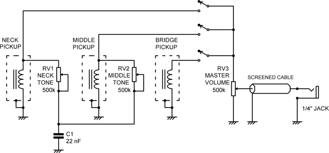
Figure 12.3 Guitar wiring for three pickups with tone and volume controls.
Adding a second or third pickup, as in Figure 12.3, greatly increases the possible arrangements. There will be switches to select which combination of pickups and pickup phase is used. These are shown as separate switches in the schematic but in practice are combined as three-way or five-way lever switches. These do not follow standard switch nomenclature, and things can get rather complicated, as usually wiring diagrams rather than schematics are provided, with the internals of the switch remaining enigmatic. [8] Note how the treble-cut capacitor C1 is shared between the tone controls. There is more on guitar wiring in Wikipedia. [9]
Guitar Leads
The pickup and internal guitar wiring are at high impedance, and only a small amount of shunt capacitance will cause losses at HF. Traditionally, a guitar was connected to its amplifier by a long curly lead to allow the player to move about, and this will typically have a capacitance between 52 and 190 pF/metre. [10] This can be effectively dealt with by having an active preamp in the guitar body (battery powered) with a low output impedance. Many guitarists now use radio links.
The classic way to reduce the effect of lead capacitance is the use of a driven guard screen, as in Figure 12.4. [11] There is an extra screen between the grounded screening foil, and this is driven by a signal that is the same as is coming in on the hot conductor from the pickup. Since there is no signal transfer between them (as there is no voltage difference between them), the capacitance causes no shunting effect. The outer screen is retained as a ground path and to prevent crosstalk from the driven inner screen. There will be a substantial capacitance between the driven screen and the outer screen, and the stage A2 must be designed to remain stable in the face of this.
The inner guard screen is driven by a low-impedance version of the signal coming in. This could be accomplished by connecting the input of unity-gain buffer A2 to the input of A1, but this will increase the noise current flowing in the input circuit and should not be done. One way to drive A2 is from a suitably attenuated version of A1 output, as in Figure 12.4a. However, since the attenuation of R1-R2 has to undo the gain of A1, it is neater to use R1-R2 to set the gain of A1 and drive A2 from the junction of R1-R2, which inherently gives unity gain; see Figure 12.4b.

This seems to me to be a cheap simple way of rendering cable capacitance harmless. But I have so far been unable to find an example of its use, probably because of the difficulty in finding cable with two separate coaxial screens. One example of this approach (in this case an MM preamplifier rather than a guitar preamp) is the rack-mounting Neumann PUE74 phono amplifier [12], where the use of a driven guard allows the turntable to be a long way from the preamplifier without cable capacitance being an issue.
Guitar Preamplifiers
These need to have variable gain, suitably low noise, and a high input impedance to prevent roll-off of HF content. Figure 12.5 shows a typical arrangement with gain variable from 0 to +30 dB; amplifier stages of this type are dealt with in detail in Chapter 8, where it is explained how to change the gain range from 0 to +30 dB to -infinity (-ish) to +30 dB by using a dual-gang pot. This means that if the amplifier has multiple inputs, only one control is required to go from full volume to no contribution to the mix. The maximum gain is set by the value of R4; the minimum gain with the arrangement shown is unity. R3 ensures that there is always feedback to the opamp if the pot wiper makes imperfect contact with the track.
Two jack inputs are shown, on the front and rear of the amplifier. If a jack is plugged into the front socket, its normalling contact is opened and the rear socket disabled. If neither socket is in use, the rear socket normalling shorts the amplifier input to ground, preventing the generation of a lot of noise from an open-circuit input.
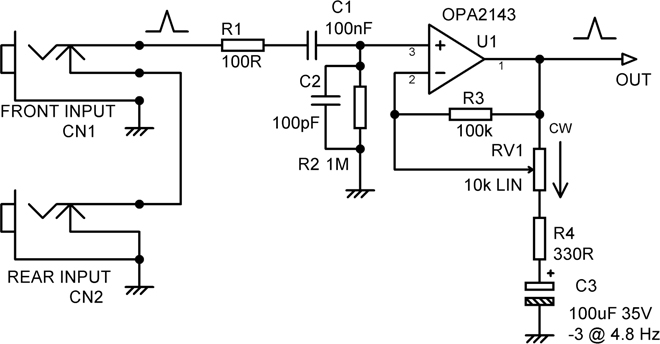
Figure 12.5 Input circuitry of a typical guitar preamplifier.
R1 and C2 make up a low-pass EMC filter to keep out RF. The opamp is shown as an OPA2143 because its FET input gives a good noise performance at high impedance. The input impedance is set at 1 MΩ simply by the choice of R2, as the input impedance of the opamp is very high indeed.
Guitar Preamplifier Noise: Calculations
The noise calculations for a guitar preamplifier are simple compared with the equivalent for MM cartridges or tape preamplifiers, because there is no equalisation to complicate things. Later tone-control stages may of course make radical changes to the frequency response, but that is another issue altogether. Figure 12.6 shows the situation; the pickup parameters are intended to be “average”, and the amplifier stage has a gain of +30 dB. A1 is here assumed to be noise free, with its voltage noise being represented by Vnoise and current noise by current-sources Inoise+ and Inoise-.
The contributions to the noise at the input of A1 are:
- The Johnson noise of the pickup series resistance Rgen. The proportion of noise from Rgen that reaches A1 input falls with frequency as frequency rises because the impedance of Lgen increases relative to Rin.

Figure 12.6 Noise model of a guitar preamplifier with typical values.
- The Johnson noise of the 1 MΩ input load Rin. Some of the Johnson noise generated by Rin is shunted away from the amplifier input by the pickup, the amount falling as frequency rises due to the impedance of the inductance Lgen rising.
- The opamp voltage noise Vnoise. This contribution is unaffected by other components.
- The noise voltage generated by Inoise+ flowing through the parallel combination of the total pickup impedance and Rin. This impedance increases as frequency rises due to Lgen.
- The Johnson noise of R0. For the values shown, and with A1 assumed to be 5534A, ignoring the Johnson noise of R0 improves the calculated noise performance by only 0.35 dB. More details of the very limited effect that R0 has on noise performance in preamplifiers are given in Chapter 9.
- The noise voltage generated by Inoise- flowing through R0. For normal values of R0, say up to 1000Ω, in this case, the contribution is negligible, affecting the total noise output by less than 0.01 dB.
These interactions get a bit complicated, so I built a mathematical model called GUITARNOISE in the form of an Excel spreadsheet, like MAGNOISE (Chapter 9) and TAPENOISE (Chapter 11). Some results from this are shown in Table 12.1. The noise is given as equivalent input noise (EIN) i.e. the equivalent noise at the input to A1; the output noise will naturally be 30 dB higher in each case. In the table, I have used both very new devices, such as the OPA828, and also ancient ones like the TL072 and even the LM741.
You can see that the best devices are recent FET input opamps (because current noise dominates with such a highly inductive input load), and they get very close to the best possible result, because the Johnson noise from the 5 kΩ series resistance of the pickup is high. Things deteriorate somewhat when we get to the OPA2134, as it is an older part with quite high voltage noise by modern standards. Predictably, the ancient TL072 is even worse, by nearly 3 dB.
| Device | EIN dBu | Noise figure dB | Notes |
|---|---|---|---|
| Noiseless | –110.44 | 0 | Reference condition |
| AD8656 * | –110.31 | 0.13 | Released Apr 2005 |
| OPA828 * | –110.17 | 0.27 | Released Sept 2018 |
| OPA2156 | –110.10 | 0.34 | Released Sept 2018 |
| OPA2134 | –109.44 | 1.00 | Released 1996 |
| TL072 | –106.79 | 3.65 | Old |
| 2SB737 70uA | –101.73 | 8.71 | Hybrid discrete–BJT/opamp |
| 5534A | –101.40 | 9.04 | |
| 5532 | –96.97 | 13.47 | |
| LM741 | –96.68 | 13.76 | Current noise from measurements |
| OPA1622 | –95.87 | 14.57 | Released Nov 2015 |
| LM4562 | –89.97 | 20.47 |
* No current-noise spec given by manufacturer’s data sheet. Presumed negligible.
However, even that is better than any of the bipolar input devices further down the table. The 5534 is a reliably low-noise part in many low-impedance applications, and its balance of voltage and current noise is almost ideally suited to moving-magnet cartridges, but here the relatively high current noise, combined with a much higher input load inductance than either MM cartridges or tape heads, makes it 8 dB noisier than the OPA2143. However, the OPA2134, at time of writing, is around five times the price.
The 2SB737 entry takes the voltage and current noise for a single bipolar transistor, the assumption being it is combined with an opamp that supplies open-loop gain for linearisation and load-driving ability. This is about as good as bipolar technology is going to get, and it’s still 5 dB noisier than the ancient TL072. The 5534 and 5532, which are so often the go-to opamps for low noise, do not work well here because they have relatively high current noise, and the input load impedance is high. Even the venerable 741 does better than the LM4562 opamp; the latter works very well with low impedances but is a really bad choice here. Be aware that the recent devices are only available in surface-mount packages. (NB: The AD8655 is the single version of the AD8656 dual opamp.) Factoring in cost and the availability of a DIP version, the OPA2134 is the recommended part here. I have used it very successfully in bass guitar amplifiers.
It is instructive to see how the noise performance varies with the parameters in Figure 12.6. If we use the OPA2134, then Table 12.2 shows how the EIN increases as pickup inductance increases. Table 12.3 demonstrates how the EIN increases as the pickup series resistance increases, as you would expect. The “load synth advantage” column is explained further on.
| Coil Lgen | Coil Rgen | EIN | 20x load synth advantage | |
|---|---|---|---|---|
| Opamp | Henrys | Ohms | dBu | dB |
| OPA2134 | 1 | 5000 | –110.84 | 1.91 |
| OPA2134 | 1.5 | 5000 | –109.44 | 3.25 |
| OPA2134 | 2 | 5000 | –108.15 | 4.39 |
| Coil Lgen | Coil Rgen | EIN | 20x load synth advantage | |
|---|---|---|---|---|
| Opamp | Henrys | Ohms | dBu | dB |
| OPA2134 | 1.5 | 1000 | –110.28 | 4.42 |
| OPA2134 | 1.5 | 5000 | –109.44 | 3.25 |
| OPA2134 | 1.5 | 10,000 | –108.57 | 2.47 |
| Coil Lgen= | Rin | EIN | 20x load synth advantage | |
|---|---|---|---|---|
| Henrys | Ohms | dBu | dB | |
| OPA2134 | 1.5 | 100,000 | –107.40 | 6.75 |
| OPA2134 | 1.5 | 500,000 | –108.32 | 4.98 |
| OPA2134 | 1.5 | 1,000,000 | –109.44 | 3.25 |
| OPA2134 | 1.5 | 2,000,000 | –110.52 | 2.14 |
| OPA2134 | 1.5 | 5,000,000 | –111.57 | 1.06 |
Table 12.4 shows how EIN increases as the load resistance across the pickup Rin decreases.
Counter-intuitively, EIN worsens as the load resistance decreases; see Chapter 9 for explanation.
Now, about those load-synthesis columns. Load synthesis is a way of decoupling the physical resistance of a resistor from its loading value. See Chapter 9 for how this works to reduce noise. The rightmost columns of Tables 12.3 and 12.4 show how the advantage varies with pickup inductance and pickup series resistance. You can also see in the fourth column of Table 12.4 that EIN improves as the value of Rin increases. Using 20-times load synthesis (i.e. the actual resistor is 20 times the loading on the pickup) gives a loading effect of 1 MΩ but a noise-generating resistance of 20 MΩ, which is quieter. It gives a quite significant reduction in noise; with the values shown in Figure 12.6, there is a 3.25 dB improvement. The advantage increases with pickup inductance.
Guitar Preamplifier Noise: Measurements
Calculations are all very well, but sooner or later you will have to do some measurements and face up to the real world. As a baseline, I took the circuit of Figure 12.5 (at maximum gain of +29.9 dB) with a short circuit across the input; GUITARNOISE gives an EIN for these conditions of -116.1 dBu. Measurements gave noise out of -85.7 dBu (usual conditions) and so an EIN= -115.6 dBu, which is about as close as you are likely to get in this imperfect world. Being a cautious person, I repeated the measurement with a 1 kΩ input termination. GUITARNOISE gives EIN= -115.1 dBu, while the measured EIN was -114.8 dBu. This is reassuring but a long way from the real highly inductive input loading.
Verifying the calculations leading to the tables is very difficult because pickups are of course designed to pick up magnetic fields, and so they do, even in what would be thought to be an electrically quiet environment. Using standard (non-humbucking) pickups, the noise is utterly submerged in hum at 50 Hz and all its harmonics, I estimate by at least 30 dB. The ideal test load would be a tapped (to vary the inductance) toroidal inductor inside several nested mumetal boxes, but that is not a component often found on the shelf, or indeed anywhere else.
My attempted solution was to get hold of a thick piece of iron pipe (apparently known as “barrel” rather than “pipe” in the construction business because of its greater thickness, resembling the barrel of a gun). The pipe section I used was 242 mm long, 47 mm outside diameter, 5 mm wall thickness. It came from a building site so is presumably ordinary mild steel. It is a substantial piece of metal weighing 1.1 kg, and you wouldn’t want to drop it on your foot. See Figure 12.7 for the arrangement. I have to say that this did not work very well. Various standard (non-humbucking) pickups were tried, but the circuit noise was still completely dominated by 50 Hz hum and harmonics, by some 20 dB.

Having failed with a standard pickup, the obvious recourse is to use a humbucking pickup. The one I obtained is an Entwhistle X2-B (neck version) [13], which has a DC resistance of 7870 Ω on one winding and 8450 Ω on the other; I have no idea why they are different. The inductance is unknown, but taking 1 Henry total (both coils) as a guesstimate, EIN calculates as -108.4 dBu, which gives -78.5 dBu at the amplifier output. An OPA2134 opamp was used.
The pickup is naturally about twice the size of a simple pickup and so regrettably would not fit into the same steel pipe. Using the amplifier in Figure 12.5, at its maximum gain of +30 dB, and just one half of the humbucker, the hum output was -45 dBu. Using both halves to get the humbucking action, the output was -59.9 dBu, which just goes to show that humbucking works. However, this was still way above the noise level.
The pickup has its external metal bracket grounded, but for some reason, only 2 of the 12 pole-pieces are grounded. Electric fields were clearly contributing to the effect of magnetic fields. Putting both the preamp and the pickup in a completely screened box solved this problem and reduced the hum level to -70.5 dBu in a 22–22 kHz bandwidth, and real white noise was now visible. There was no magnetic shielding. Switching in the 400 Hz third-order high-pass filter in the AP reduced the reading to -78 dBu, and the GUITARNOISE calculation (more or less) aligns with measurement. The spectral distribution of noise and hum from the humbucking pickup and the effect of the 400 Hz filter are shown in Figure 12.8.

It would be very desirable to repeat this with a range of humbucking pickups, but buying them would soon get expensive. The conclusion so far is that it will be a real struggle to get the interference acquired from the pickup below the noise floor of the amplifier. Given this situation, it is questionable if anything will be gained by using the new and expensive FET-input opamps. The OPA2134 would seem appropriate for even high-end guitar amplifiers. It seems unlikely that load synthesis will give tangible benefits in this application and become popular for guitar inputs, but in audio, you never know…
Guitar Amplifiers and Guitar Effects
Electric guitars are traditionally operated into valve amplifiers, often with integral loudspeakers. The amplifier distortion and the frequency response of the speaker can radically alter the sound, to the extent that it is sensible to regard the guitar/amp combination as a single instrument. An alternative approach is to run the guitar directly into a mixing console without any amplification (see the next section on direct injection) and, if desired, put through an amplifier later.
Electric guitars are commonly used with effects boxes between guitar and amplifier. These exist in profusion but can be roughly classified thus:
- Altered dynamics: compressors, limiters, and swell (volume control) pedals.
- Added distortion: produced by fuzz-boxes, hard clipping. The hexafuzz, which, as noted, requires a hexaphonic pickup. Soft clipping using diodes, JFETs or LEDs. My own contribution in 1975 was the Sound Folder, which made precisely zero penetration into the marketplace.
- Altered frequency response: The most popular of these effects is the wah-wah pedal, which moves a resonant peak up and down in frequency. Its popularity is due to the way it partially emulates the movement of formants [14] in human speech and singing. A more extreme version is the voice box (also called talk box or voice bag) in which a tube from a small speaker in a box is placed in the mouth and mouth movements move the resonances up and down. As several performers have found out the hard way, excessive bass levels tend to make you throw up.
- Modulation: this vague term covers phasing, flanging, tremolo (amplitude modulation), and vibrato (frequency modulation). It also covers the ring modulator, in which one sound is multiplied with another. The ring part refers to the ring of four diodes used in the original versions.
- Time manipulation: includes looping boxes, which allow a musical phrase to be repeated endlessly, straightforward delays, and reverberation.
- Altered pitch: digital pitch shifters [15] and auto-tune [16] devices.
There are many possibilities and a comprehensive outfit of effect boxes can easily add up to a dozen or more, and to avoid endless plugging and unplugging at gigs, they are usually fixed to a guitar pedalboard. Sometimes it is a good idea to make the last box in the chain a noise gate.
Guitar Direct Injection
Direct injection (or DI) refers to running the guitar output directly into a mixing console without the use of an amplifier. The problem is that the microphone input will not be likely to have an input impedance greater than 2 kΩ, which puts far too much loading on a pickup. A line input will have a higher input impedance, probably greater than 10 kΩ, but this is still far too low for a pickup.
There are passive and active DI boxes. A passive DI box contains a transformer with a suitably high turns ratio that makes the mixer input look like a high impedance to the pickup and usually converts the output to a balanced format. A typical arrangement is shown in Figure 12.9, using the Jensen JT-DB-E transformer, which is a specialised design for this application. The turns ratio is 12:1, giving an impedance transform ratio of 12 squared = 144 times. This turns the 1 kΩ input impedance of a mixer mic input into 144 kΩ, which is more like a reasonable load on a guitar pickup. The output is balanced and at a low impedance, so long cable runs can be used without capacitance losses or the ingress of interference.

Most DI boxes have a direct output that can be plugged into an amplifier while the clean signal is sent to the mixer. Most also have a ground-lift switch that separates the guitar ground from the mixer ground. This implies that there IS a guitar ground, which is of course essential for safety, or you may die standing up in a very literal manner. On the few occasions when I have been called upon to design in a ground-lift facility, I have always used a wire wound resistor for R1 so that it will not fail open-circuit on minor transients. The capacitor C1 ensures that RF still goes to ground when the switch is open. Some DI boxes include switched or variable attenuators to prevent overload of a mic input.
Active DI boxes do not use a transformer but instead an amplifier to buffer the pickup from the mixing console and provide a balanced output. They are usually battery powered to maintain ground isolation.
References
[1] Skow, Vaughn https://wgsusa.com/ultimate-5-pickup-fender-stratocaster-worlds-most-versatile-guitar Accessed Sept 2019
[2] Wikipedia https://en.wikipedia.org/wiki/Pickup_(music_technology) Accessed Sept 2019
[3] Wikipedia https://en.wikipedia.org/wiki/Humbucker Accessed Sept 2019
[4] Wikipedia https://en.wikipedia.org/wiki/Humbucker#Alternative_humbucker_designs Accessed Sept 2019
[5] YouTube www.youtube.com/watch?v=Jodhm5mvvqE Roland GR-100 Accessed Aug 2019
[6] Joness, W. S. www.joness.com/gr300/G-707.html Accessed Aug 2019
[7] Hiscocks, P. www.syscompdesign.com/wp-content/uploads/2018/09/guitar-pickups.pdf Accessed Aug 2019
[8] Stewmac www.stewmac.com/Pickups_and_Electronics/Components_and_Parts/Switches/ Accessed Sept 2019
[9] Wikipedia https://en.wikipedia.org/wiki/Guitar_wiring Accessed Sept 2019
[10] Shootout www.shootoutguitarcables.com/guitar-cables-explained/capacitance-chart.html Accessed Sept 2019
[11] Wikipedia https://en.wikipedia.org/wiki/Driven_guard Accessed Sept 2019
[12] Vogel, Bernhard The Sound of Silence 2nd edition. Springer Verlag, pp 220–224 (Neumann PUE 74 preamplifier)
[13] Entwhistle www.entwistlepickups.com/pickup.php?puid=X2 Accessed Sept 2019
[14] Wikipedia https://en.wikipedia.org/wiki/Formant Accessed Sept 2019
[15] Wikipedia https://en.wikipedia.org/wiki/Pitch_shift Accessed Sept 2019
[16] Wikipedia https://en.wikipedia.org/wiki/Auto-Tune Accessed Sept 2019