
Chapter 19
Toward Resilience of the Electric Grid
Jiankang Wang
Department of Electrical and Computer Engineering, Ohio State University, Columbus, OH, USA
“Expect the best, plan for the worst, and prepare to be surprised.”
- Denis Waitley
Chapter Menu
Electric Grids in Smart Cities
Threats to Electric Grids
Electric Grid Response under Threats
Defense against Threats to Electric Grids
Objectives
- • To understand the structure and basic operating principles of the electric grid, its connection to smart cities and interdependence with other critical infrastructures.
- • To understand possible threats to electric grids from natural disasters and malicious intents. As some of these threats have manifested themselves through historical events, others were recently enabled by advancement of smart cities' cyber infrastructures.
- • To understand the cyber and physical causal chains in the electric grid from initial threats to final consequences, and to show existing metrics that enable us to quantify these consequences and probabilities of their occurrences.
- • To discuss the responding mechanisms of the electric grid and other sections in smart cities, which prevent, intercept and mitigate these threats and make the electric grid resilient.
19.1 Electric Grids in Smart Cities
Electricity provides lifeblood to urban operations. Urban infrastructures are operated on electricity for food preservation, water treatment, heat and light, phone service, Internet, factories, hospitals, and emergency response. Disruption of electricity will degrade or cease all these services and normal function of critical municipal departments, such as fire stations and police stations. In smart cities, which host many highly integrated and interdependent layers, prolonged disruption would seriously affect every infrastructure. An outage of more than 10 days will result in 80% of economic activity ceasing [1]. For power delivery systems in cities, continuously supplying electricity of satisfactory power quality remains the top priority.
Today's power systems are described by the industry as “reliable, but not resilient [2].” With sufficient redundancies, they can easily handle failures of small numbers of components due to probabilistic events. For example, you may not notice any lights flickering if a district transformer were taken offline due to an accidental short circuit, because its load was transferred to the backup margin of other transformers in the service area. However, reliability to handle random disturbance does not naturally lead to resilient response to specific events. While a power system's reliability can be improved by adding redundancies, its resilience requires awareness of the existence of system vulnerabilities and strategic planning of the system's configuration.
Threats that cannot be handled by redundancies are mainly of two kinds: weather hazards and malicious attacks. Unlike random events, they are much less controllable and usually engender high impact. Extreme weather hits power systems in a wide range and could physically damage multiple critical grid assets in a fairly short duration, making backup transfer impossible. For example, in 2012, the Northeastern United States was struck by Hurricane Sandy. Over 100,000 primary electrical wireswere destroyed, several substation transformers exploded, and numerous substations were flooded. This led to the disconnection of approximately 7 million people [3].
Compared with extreme weather, malicious attacks to power delivery systems could be more dangerous, because they usually involve malicious intent. They may aim at disrupting power to a service area or target a critical grid asset. Redundancies designed to absorb random disturbances of small magnitudes are incapable of defending against these intentional actions of high intensity. Moreover, attacks are usually launched to the most vulnerable parts of power delivery systems. In 2013, attackers near San Jose disabled 17 substation transformers by shooting through a chain-link fence. The bullet holes caused the transformers to leak thousands of gallons of oil and ultimately overheat. The backup capacity of neighborhood transformers barely supported the system through the attack; only because it occurred in early morning when the load was low, the backup capacity became sufficient [4].
More sophisticated malicious attacks take place on the cyber level of power systems. As the power delivery system is evolving, an increasing number of sensors applied to the grid allow for both improved flexibility and increasing automation. However, such an increase in automation also increases the number of on-ramps for cyber attacks. The latest publicized cyber attack on industrial control systems was the Stuxnet worm. The objective was to corrupt a specific type of programmable logic controller (PLC) by rewriting parts of the code and turning it into the attacker's agent. With modifications, it could become a serious threat to power grids [2]. In smart cities, this increased integration with the communication infrastructure can leave the grid vulnerable as layer upon layer of connectedness results in an increasing amount of trust in suppliers.
Above reliability, a power system resilient to these threats is sought after for smart cities. As written in the US Presidential Policy Directive 21, “resilience is the ability to prepare for and adapt to changing conditions and withstand and recover rapidly from disruptions.” To build a resilient grid, the following questions need to be addressed: (i) What can go wrong? (possible threats); (ii) What are the consequences? (grid response and causal chain); (iii) How likely are the consequences to occur? (failing conditions); and (iv) How is a normal status restored? (resilient response). In this chapter, we wish to answer these questions by presenting both real examples and technical principles of power systems' response to cyber and physical threats.
The rest of this section briefly introduces the background of power systems and terminologies. Section 19.2 presents real threats experienced by power systems in history, together with modeling methods for the threats. Section 19.3 unfolds the causal chains of the past major events to power systems, evaluates the consequences of possible attacks, and presents vulnerability assessment methods. Methods to improve resilience of power systems are discussed in Section 19.4. We assume that readers have basic knowledge of electrical engineering but no prior knowledge in power systems.
19.1.1 Structure of Power Systems
19.1.1.1 Vertical Structure
Modern power systems can be dissected into three layers: (i) a physical power grid (denoted as the grid), including generators, power delivery equipment, and lines, loads, and protective devices; (ii) a control layer, including central and local decision-making units; and (iii) a monitoring layer, including meters, actuators, and hardware to store and transmit measurements (see Figure 19.1). In the context of cyber–physical systems, the power grid is physical, whereas the monitoring and control layers are its cyber subsystems. The monitoring layer collects, transmits, processes, and analyzes the measurement over various service areas and at various rates. The control layer determines the current system status based on processed measurements and makes decisions accordingly. These decisions are passed onto intelligent electronic devices (IEDs), which finally trigger mechanical actions on the (physical) grid.
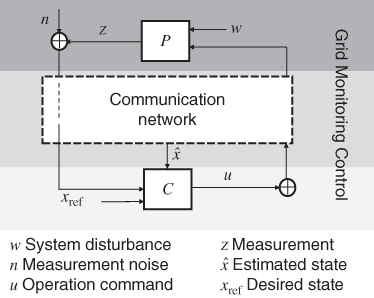
Figure 19.1 Vertical structure of power systems.
The interaction of this layered structure may be illustrated by an example of loss minimization in a local distribution grid. On the monitoring layer, nodal meters measure voltage and current values and transmit them through the supervisory control and data acquisition (SCADA) system [5]. On the control layer, the processed voltage and current values are input to the loss minimization algorithm in the distribution management system (DSM) software. Finally, on the grid, the voltage regulators receive control commands and change their tap positions accordingly. Following the voltage adjustment, power flows on the grid are redistributed, rendering minimum power delivery losses.
The physical grid consists of four sections: the generation section where primary energy is converted into electric power (electricity), transmission and distribution sections that transport this power, and the load section that uses power. Cities rarely host the generation and transmission sections. Large generating units are usually located outside densely populated areas. Urban electric grids take in power from their upstream transmission networks, transform it into lower voltages, and deliver it to commercial centers, small enterprises, residential users, factories, and municipal departments; they mainly consist of the distribution and load sections. Because of their function, we refer to the part of power systems in cities, including both its physical and cyber subsystems, as power delivery systems.
19.1.1.2 Transmission
The transmission system (above 138 kV) transports power from generating units to all the power delivery systems within its operation region. Events striking power systems at the transmission level, if not mitigated in time, may roll on to cascading blackouts to downstream power delivery systems. The transmission network is composed of power lines and stations/substations. In cities where real estate is valuable and transmission towers cannot be afforded, transmission lines sometimes adopt insulated cables buried underground.
19.1.1.3 Station and Substation
The connection between power delivery systems and transmission systems occurs at distribution substations. Stations and substations are common targets of both physical and cyber attacks. Stations and substations house transformers, switchgear, measurement instrumentation, and communication equipment. High-voltage (HV) transformers carry 60–70% of the nation's electricity. They are designed and manufactured to custom specifications for a specific network application. If an HV transformer is damaged, replacement could take from 5 to 20 months and cost from $2 million for a 230 kV unit to $7.5 million for a 765 kV unit [6]. The situation becomes more threatening as the power system will be operated under high stress and in a more vulnerable condition until replacement is completed.
Cyber attacks may happen at substations to switchgear and measurement instrumentation. Switchgear includes circuit breakers and other types of switches used to disconnect parts of the transmission network for system protection or maintenance. With the promotion of power system automation, more of these switchgear become digital and remotely controllable [7]. Cyber attacks that falsify control command can de-energize an important circuit and cause large-scale disturbances. Measurement instrumentation collects voltage, current, and power data for monitoring control and metering purposes. Communication equipment transmits these data to control centers and also allows switchgear to be controlled remotely. Cyber attacks to any of these devices will sabotage timely remedial actions when a system goes through abnormal status. Examples of these attacks are given in Section 19.2.
19.1.1.4 Distribution
Power delivery systems consist of distribution networks, loads, and their control and monitoring layers. Primary distribution networks operate from 2 kV to 35 kV, delivering electricity from substations, which are connected to transmission level. Transformers on primary distribution networks further step down the voltage to 120 V/480 V. The wires that operate at this low voltage level and are directly connected to end users are secondary distribution networks [8]. Power networks that are operated between 35 kV and the transmission voltage level (138 kV) are referred to as the sub-transmission level1.
In cities, distribution networks are usually formed in mesh topologies, whereas in suburban and rural areas radial topologies are more dominant. Compared with radial topologies, mesh networks are more expensive but embody higher reliability and operation flexibility. In a contingency, they permit a load to be served through an alternative path when there is a problem in the original path. On the other hand, they may complicate the deployment of protection schemes due to the presence of multiple power flow paths. Cyber attackers can take advantage of this by hacking into the distribution management systems (DMS) and cause electricity disruption.
19.1.2 Operation of Power Systems
Power systems are operated through a combination of automated control and actions that require direct human intervention. The objective of real-time operationis to ensure that the system stays stable and protected while meeting end-user power requirements. System stability requires a precise balance between power generation and consumption at all times. This requirement can be explained by the swing equation
When the total power generation ![]() does not meet the total demand
does not meet the total demand ![]() , the generation's power angle
, the generation's power angle ![]() changes with time and results in frequency deviation. The frequency deviation also depends on the system inertia
changes with time and results in frequency deviation. The frequency deviation also depends on the system inertia ![]() and damping
and damping ![]() , which can be improved through transmission technologies, such as flow control devices and power system stabilizers [9]. The equation expresses the energy balance dynamics within power systems. Consider the entire US power system as one generator whose rotor rotates at 60 Hz, the standard frequency in North American power systems. (In actuality, the rotation speed is likely to be different and varied for many generators. Here we “group” all these generators to rotate at one speed for explanatory convenience.) If there is more consumption than generation (
, which can be improved through transmission technologies, such as flow control devices and power system stabilizers [9]. The equation expresses the energy balance dynamics within power systems. Consider the entire US power system as one generator whose rotor rotates at 60 Hz, the standard frequency in North American power systems. (In actuality, the rotation speed is likely to be different and varied for many generators. Here we “group” all these generators to rotate at one speed for explanatory convenience.) If there is more consumption than generation (![]() ), the rotor will release kinetic energy by rotating slower to make up the energy supply needed. Likewise, if there is more generation than consumption (
), the rotor will release kinetic energy by rotating slower to make up the energy supply needed. Likewise, if there is more generation than consumption (![]() ), the rotor will store the extra generation as kinetic energy and rotate faster. This behavior is known as “inertial response.” The rotor's position gives the power angle
), the rotor will store the extra generation as kinetic energy and rotate faster. This behavior is known as “inertial response.” The rotor's position gives the power angle ![]() , and its movement dynamics are described by the frequency
, and its movement dynamics are described by the frequency ![]() and the frequency's deviation
and the frequency's deviation ![]() .
.
Sudden change of load or loss of generating units will lead to unbalance. Physical and cyber attacks at generators and power transmission lines can easily create such unbalance. For example, cyber attacks can maneuver multiple generators simultaneously. If the balance is not regained in a short time, the system power angles become unstable – its frequency can exceed allowable bounds. An unstable frequency can lead to unstable voltages and result in equipment damage as well as blackouts. This phenomenon of transient instability does not originate from power delivery systems, which do not have large generating units and only absorb power but not export power to elsewhere. It happens at the transmission level and propagates to power delivery systems downstream.
19.1.2.1 Control
The principle of control is to maintain the balance between generation and load, ensuring that the frequency and voltage of the power system stay within the established system standard. The grid response under disturbance depends on its control mechanisms.
Governor control is the initial corrective action to any change of load or generation. The governor is a device that controls the mechanical power driving the generator via the valve limiting the amount of primary energy, such as steam, water, or gas flowing to the turbine. The governor acts only in response to locally measuredchanges in the generator's output frequency, which is related to the rotor's rotation speed. The governor responds within seconds, and the rotational speed of the rotor (thus the output frequency of the generator) stays constant after the governor's response [9]. The resulting frequency will be lower than the initial frequency, 60 Hz, if the load dropped or higher if the load increased.
Governor control is implemented to regain the local unbalance between the electric load and mechanical output of a generator. Automatic generation control (AGC) is used to bring all the generators within a control region back to 60 Hz. AGC can refer to two related concepts: (i) a device installed on generators and (ii) the control scheme that is implemented through these devices. A control area only has a select number of generators installed with AGC, which are of large capacities or at vital locations in the transmission network topology. After governor control, the control center in a region measures the difference between actual and scheduled net power flows with other control areas. This difference is called the area control error (ACE) [10]. A positive ACE means that the total amount of generation within the control area is more than the scheduled amount, because of a previous load drop and a governor's response. Receiving this ACE, the control center automatically sends signals to generators equipped with AGC to decrease the generator's output. Attacks at control systems have been studied for contaminating ACE signals or manipulating AGC on generators directly. Due to the natural influence of AGC-equipped generators, malicious manipulation will cause severe consequences on a large scale. Examples of these attacking models are presented in Section 19.2.
Beyond a certain level of power imbalance, generation reserves will be resorted to. The generation reserves in a control region are usually made of additional generating units that are on standby or those that can ramp up their output on request [10]. However, when all other options for balancing power have been exhausted, the system operator must proactively reduce the load, generally referred to as load shedding. Load shedding can be accomplished in the form of temporary power interruption to contracted users, voltage reductions, or rotating blackouts. Sometimes when rapid response is demanded, load shedding is automatically implemented through emergency control and protection schemes.
19.1.2.2 Scheduling
Scheduling ensures the long-term balance between generation and load. It determines which generating units should operate and at what power level, and it is accomplished on a predetermined fixed time interval. The objective is stated via economic means, to minimize cost, and subject to generation and transmission constraints. Scheduling consists of economic dispatch and unit commitment, each covering two overlapping time ranges.
Economic dispatch minimizes the overall production cost of electricity, considering the power delivery losses, by optimally allocating projected demand to generating units that are online. Computers at control centers run optimization algorithms, typically every 5 or 10 min, to determine the dispatch for the next hour and send these decisions to all the generators. Unit commitment decides when generators should start up and shut down, as it is not practical to keep all the generators online all the time. It is typically done 1 day ahead and covers dispatch for periods ranging from 1 to 7 days [10, 11].
Due to their financial meaning, the scheduling process is likely to be targeted by attackers motivated by increasing their own benefits or harming competitors' benefits. The consequence, nevertheless, is more than monetary loss and can lead to efficiency reduction, even frequency instability. Since the malicious intent may come from someone who actually owns the physical generating assets, the attack path is not confined to the cyber layers of power systems and can be difficult to defend against.
19.1.2.3 Protection
Another important aspect of the operation of power systems is protection. Protection devices are applied to specific equipment, including motor loads, generators, transmission lines, and other power delivery equipment. They serve to protect both grid assets and humans in contact with them. The coordinated operation of a group of protective devices on electric grids is defined as a protection scheme2. Protection schemes are designed to benefit an entire power system rather than only protecting individual devices. Protection is achieved using sensing equipment (including current/voltage transformers and digital sensors), de-energizing equipment (such as circuit breakers and reclosers), and relays, which are the decision-making units.
When a fault is detected on the electric grid, the corresponding protection scheme selects the range of circuits to be de-energized. This range may be as limited as the faulted device itself or as great as a full section of the distribution network. The selection should minimize the loss of load and also depends on the system operation status, fault type, and location [12]. By removing the circuit, the electric grid benefits from eliminating the stress and preventing further equipment damage and any associated expensive and lengthy repairs. Protective action must be fast (usually in fractions of a second) and accurate.
Power systems, in order for the protection schemes to work, are designed with sufficient redundancies, so that they can withstand the removal of one or several elements without unduly stressing the overall physical grid. As discussed in Sections 19.3 and 19.4, the inherent strength of the physical grid is the best defense againstcatastrophic failures. However, if the system is already stressed for some reason, such as equipment outages, heavier than normal loads, or extreme weather, this corrective action may exacerbate the situation and result in wide-area outages.
By targeting protection schemes, cyber attacks can cause power failure in a fast and direct way. One fear is that if attackers can hack into relays, they could de-energize circuits by tripping circuit breakers. Another possibility is to suppress protective actions under real faults or to launch joint cyber–physical attacks, with the physical attack to cause faults. Studies on both of these attack models are presented in Section 19.2.
19.1.2.4 Distribution Automation
Compared with transmission networks, distribution networks are usually planned with less expensive technologies, mainly because their scale of impact is limited to local areas. During recent years, distribution automation (DA) has been promoted in urban power delivery systems. In densely populated urban areas, like New York City, cities that concentrate highly functional government departments, like Washington, D.C., or areas that encompass manufacturers and harbor information entities, like Silicon Valley, electric operation cost is nontrivial, and failure of power delivery systems will lead to substantial economic losses.
IEEE defines a DA system as one that enables an electric utility to remotely monitor, coordinate, and operate distribution components in a real-time mode from remote locations. The principal objective of DA can be summarized as energy conservation and self-healing under faults [13]. Two prominent examples are automated fault detection, isolation, and restoration (FDIR) and optimization of system voltage and power flows. In an automated distribution network, voltage values are collected and power flows are monitored in real time. Once a fault is detected, circuit breakers and sectionalizers are controlled remotely to de-energize the faulted circuit and reroute the power to restore the loads. With regard to energy conservation, power delivery losses can be minimized with voltage control devices such as switched capacitor banks, load tap changers (LTCs) on the substation transformers, or voltage regulators installed along distribution feeders.
On the one hand, DA reduces the risk of power failures under probabilistic events, like tree intrusion into power lines, and disastrous weather. On the other hand, its communications, IT infrastructure, and sensors create vulnerabilities to cyber attacks. As renewable energy sources, such as roof photovoltaic (PV), are aggressively promoted under the smart cities context, urban electric grids can no longer be considered as passive power sinks. If manipulated by adversaries, DA systems can even drive flow back to its upstream transmission level. Correlated attacks at the distribution level can cause catastrophicconsequences.
19.2 Threats to Electric Grids
Power systems are designed with redundancies to handle random disturbances of small magnitudes, such as tree intrusion to power feeders or automobiles striking power poles. However, the design cannot afford infinite redundancies to withstand or quickly recover from intentional destruction of critical components or damage inflicted simultaneously on multiple components. Threats that cannot be handled by redundancies mainly come from weather hazards and malicious attacks. This section presents historical examples of threats to power systems and their threat models.
19.2.1 Threats to the Physical Grid
The vulnerability of modern power systems is increased by the fact that the power industry is moving from vertically integrated structure to deregulated entities, which are responsible for their own economic benefits in a competitive electricity market environment [14]. Under the vertical structure, utilities have the obligation of providing reliable and satisfactory service. The recent restructuring of the power industry put forward the cost pressure from consumers and regulators, deferring investment to strengthen and upgrade the grid. Consequently, many parts of transmission networks are heavily stressed, which would directly affect the downstream power delivery systems in any adverse occasion.
19.2.1.1 Threats from Weather Hazards
In the 2013 report from the National Research Council (NRC) on power delivery systems, weather hazards are identified as the main threat to the national grid and the original cause of 60% cascading blackouts worldwide in the past 50 years, since the 1965 blackout [3].Disastrous weather events directly destroy or damage power delivery components simultaneously and on a great scale. Stations and substations are less affected. The major damage is concentrated on the transmission and distribution networks, as transmission lines and distribution feeders are sparsely located over a distance. Strong wind and heavy ice can easily bring down transmission lines and distribution feeders, interrupting the power delivery passages. Storms and earthquakes can take out a transmission tower, which disables all circuits amounted to it, manifesting domino effect. In the winter of 1998, an ice storm struck Quebec and the Northeastern United States; 2.3 million customers lost power. In 1999, Taiwan wasaffected by transmission tower collapse due to earthquake [3].
Storms take an annual toll on many distribution networks. Fortunately, utilities are usually prepared for such emergencies and often pool their resources to aid each other in restoring service. The single-contingency criterion (![]() ) and multiple-contingency criterion (
) and multiple-contingency criterion (![]() ) network planning is used in reliability planning for this purpose [8]. DA technologies that enable faster reconfiguration of a network are often deployed in cities, which demand high reliability, to reduce the weather-related losses. If a weather event is widespread and long lasting, neighboring utilities might lose their backup, and this method becomes ineffective. For example, in 1990, Hurricane Sandy caused Long Island to lose all ties to Connecticut and New Jersey, and New York City lost all ties to New Jersey. The flooding resulted in over 2 million customer outages. “While utilities may typically prepare for an N-1 or N-2 event…It is an N-90 contingency,” as noted by the New York Independent System Operator (NYISO) [3].
) network planning is used in reliability planning for this purpose [8]. DA technologies that enable faster reconfiguration of a network are often deployed in cities, which demand high reliability, to reduce the weather-related losses. If a weather event is widespread and long lasting, neighboring utilities might lose their backup, and this method becomes ineffective. For example, in 1990, Hurricane Sandy caused Long Island to lose all ties to Connecticut and New Jersey, and New York City lost all ties to New Jersey. The flooding resulted in over 2 million customer outages. “While utilities may typically prepare for an N-1 or N-2 event…It is an N-90 contingency,” as noted by the New York Independent System Operator (NYISO) [3].
Extremely hot weather can overheat the transmission lines and distribution feeders. This heat itself, though causing extra power delivery losses, is unlikely to damage the lines and feeders. However, overheated lines and feeders will sag, which lower the clearance to ground and result in short circuit by touching a tree branch or other ground objects. Such incidents are more often observed in Asian countries at the distribution level, where the ground clearance of distribution feeders is lower [15].
Among all weather disasters, solar storms are rare in occurrence (happening around every 11 years) but could entail great impact on transmission and distribution networks, transformers, and relays. Its interaction with the Earth's magnetic field can produce auroral currents, or electrojects, that follow generally circular paths around the two magnetic poles at altitudes of 100 km or more. In March 1989, the entire Hydro-Quebec power system, including the major metropolitan areas of Montreal and Quebec City, was blacked out due to a gigantic solar storm. Several large power transformers also failed elsewhere in Canada and the United States, and hundreds of relays misoperated. Power systems in the northern hemisphere suffered voltage depressions and unusual swings in real and reactive power flows [16].
19.2.1.2 Threats from Malicious Attacks
Malicious attacks on the physical grid of power systems, though generally more fearsome, entail much less cost compared with disastrous weather and are unlikely to cause damage on a large scale. In general, there are three types of malicious attacks: small-scale vandalism by small groups with limited technical sophistication, well-planned terrorist activities, and strategic war activities.
Bulk transmission substations have unique security concerns to terrorist attacks in that they are relatively soft targets; they are vulnerable to standoff attacks as well as penetration attacks by adversaries compromising the substations' perimeter fences. HV transformers are difficult to replace, which could take as long as 15 months and cost as much as US$7.5 million. At the occurrence of transformer attacks, power systems may go under transient instability, and damage to HV transformers can separate power delivery systems from generation for long periods. Such attacks were launched on a frequent basis in the United Kingdom, by the Irish Republican Army, and in Iraq, by insurgent groups [6].
During wartime, electric grids were once important targets. In particular, air planners tended to become enamored with the vulnerability of electric grids to air strikes [17]. Historically, there have been four basic strategies behind attacks on national electric systems: to cause a decline in civilian morale, to inflict cost on the political leaders to induce a change, to hamper military operation, and to hinder war production [17]. However, hardly any war attacks on electric grids were successful in history. On the one hand, the military is relatively unaffected by a loss of power, as they are a high-priority user and can be self-supported. As power technologies evolve, many military bases are innovated into a microgrid [18]. On the other hand, the induced civilian damage was usually politically counterproductive. Therefore, threat models of war attacks on electric grids are less considered.
19.2.1.3 Models for Threats on the Physical Grid
Two approaches are common in modeling threats on electric grids: high-level probabilistic models and high-risk multiple contingencies. High-level probabilistic models do not model power system physics, that is, they allow neglecting time-dependent dynamics and grid configuration changes under threats. The initial overall system stress is represented by upper and lower bounds on a range of random initial component loadings. The model is parameterized by initial disturbances from weather [19]. High-risk multiple contingencies use a deterministic approach. Failures of components are selected from the worst case rather than the most likely case or every likely case. They are used to evaluate a power system's performance under the loss of a group of its most critical components, from which a plan is concluded to reinforce the power grids.
Both methods are commonly used in modeling damage from attacks and weather to the grid. Engineers and researchers have their own preference in choosing one method over the other, depending on applications. For instance, in power system planning, high-risk multiple contingencies are used by utilities, while the high-level probabilistic method is more preferred in estimation of cascading failures among layers of civil infrastructures.
19.2.2 Threats to the Cyber Layers of Power Systems
19.2.2.1 How Secure Is the Cyber Layer of Power Systems?
The monitoring layer and control layer of a power system consist of sensors and automated and manual controls, all of which are tied together through communication networks. Early communication networks used in power systems were carefully isolated and tightly controlled. Historically, utilities typically own and operate at least parts of their own telecommunication systems, which often consist of a fiber-optic or microwave backbone connecting major substations, with spurs to smaller sites [20]. However, economic pressure from deregulation of the power industry pushed utilities to make greater use of commercially available communications and other equipment that was not originally designed with security in mind. Traditional external entities including suppliers, consumers, regulators, and even competitors now must have access to segments of the network [20].
From a security perspective, such interconnections with office and electronic business systems through other layers of communication have created vulnerabilities. Intrusions intending to bring down the power system can follow the same passage of a utility's daily operation. For example, remote access to a substation network from a corporate office or location is not uncommon for control and maintenance purposes. Dial-up, virtual private network (VPN), and wireless are available between remote access points and the substation local area network (LAN) [2, 21]. These access points are potential sources of cyber vulnerabilities.
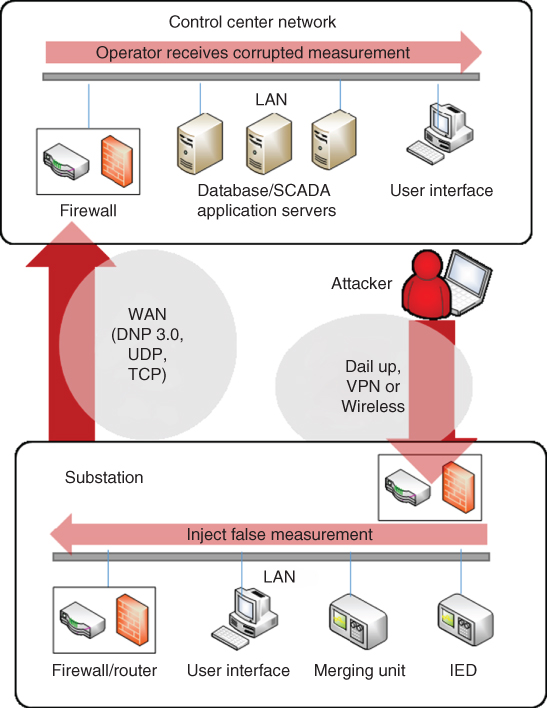
Figure 19.2 Intrusion points on the monitoring layer of power grids.
Figure 19.2 illustrates the intrusion points in a power system communication network. Intrusions can originate from remote access points within a control center or a substation. If an intrusion originates from communication networks, it needs to pass the firewalls within the control center or substation of the target. As an alternative, intrusions can contaminate user interfaces of the control center or substation directly and gain access to other facilities within the target. Activities that compromise these remote access points could steal critical information (such as grid configurations) and cause electricity disruption by opening circuit breakers. In some cases, these malicious activities could result in physical damage of key grid components, as was demonstrated in the experiment of generation self-destruction by a cyber attack, launched by the Department of Homeland Security, in March 2007 [22].
19.2.2.2 Classification of Cyber Attacks
In EPRI's 2000 survey, utilities ranked bypassing controls, integrity violation, and authorization violation [23] as their top 3 perceived threats among all attacking methods in Table 19.1. The surveyed attacking methods, however, pause at the level of communication networks and do not reflect the final consequences inflicted on power grids. Here we present a comprehensive classification of cyber attacks, which describes their attacking paths on the vertical structure of power systems: control attack, monitoring attack, control–monitoring (CM) attack, and monitoring–control (MC) attack. Figure 19.3 illustrates their attacking strategies. The rest of this section explains these four classes of cyber attacks in detail.
Table 19.1 Attacks on communication networks
| Attack | Definition |
| Authorization violation | Accessing the system without proper access rights |
| Bypassing controls | Exploiting system flaws or weaknesses by an authorized user in order to acquire unauthorized privileges |
| Denial of services | Deliberate impeding of legitimate access to information |
| Eavesdropping | Acquiring information flows, by listening to radio or wireline transmissions or by analyzing traffic on a LAN |
| Illegitimate use | Knowingly or unknowingly intruding on system resources |
| Indiscretion | Indiscriminately opening information files and so on |
| Information leakage | (Users) unintentionally providing information to a disguised third party |
| Integrity violation | Modifying or destructing messages and the computer infrastructure with no authorization |
| Intercept/alter | Intercepting and altering information flows, usually by accessing databases and modifying data |
| Masquerade | Posing as an authorized user on a network and attaining full rights of an authorized user, often enabled by having other users' passwords |
| Replay | Using information previously captured without necessarily knowing what it means |
| Repudiation | Impeding users' access to the entities from which they undertook some action such as sending a message or receiving information |
| Spoof | Deceiving users and applications to performing functions on behalf of an attacker, by falsifying the legitimacy of the attacking software/service |
19.2.2.3 Attacks on the Control Layer
The attacking classes on the control layer include a control attack and CM attack, illustrated in Figure 19.3b. In control attacks, hackers may hijack IEDs and falsify decisions. Knowledge of the original decision ![]() is not necessary. This class of attacks is essentially the same as physical attacks, in the sense that the grid's configuration is altered by control signals in a way similar to mechanical operation. For instance, the action of opening a circuit breaker through control logic and that of physically opening it on-site results in the same physical consequence on the grid.
is not necessary. This class of attacks is essentially the same as physical attacks, in the sense that the grid's configuration is altered by control signals in a way similar to mechanical operation. For instance, the action of opening a circuit breaker through control logic and that of physically opening it on-site results in the same physical consequence on the grid.
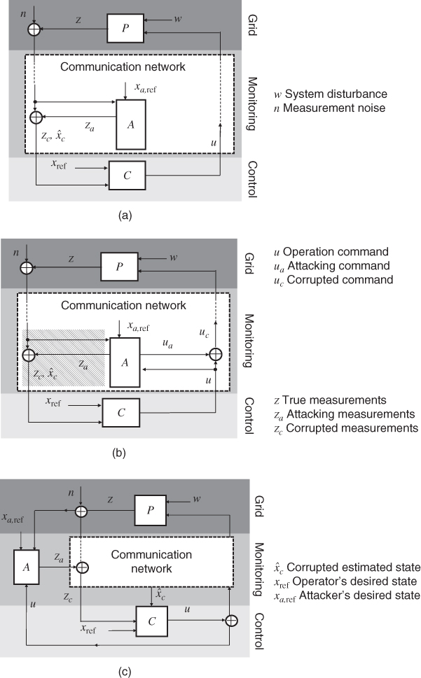
Figure 19.3 Four classes of cyber attacks on power systems. Control–monitoring attack is illustrated by (b). General control attack is illustrated also by the same diagram of (b) if taken out the shaded area. (a) Monitoring attack. (b) Control–monitoring (CM) attack. (c) Monitoring–control (MC) attack.
In 2008, hackers turned out lights in multiple cities in an unnamed country, as revealed by a senior CIA analyst. The hackers demanded extortion payments before totally disrupting the power supply of the entire country. To date, the identities of the hackers remain unknown, but the intrusion was confirmed as via the Internet [2]. In the same year, a penetration test was performed in the United States by a team of security experts. With simple rootkits, the red team broke into the security system of an unnamed utility within the first few minutes of testing [24]. More worrisome control attacks might happen on the transmission level, where losing any key components such as transmission lines or a generating unit could result in instability of system frequency and voltage.
Compared with physical attacks, the adverse consequences of attacks on the control layer can be magnified in two ways: (i) more sophisticated manipulation of the IEDs is possible, and (ii) a large number of IEDs can be manipulated simultaneously. For example, Ref. [25] shows coordinated control of a group of generators in a manner that destabilizes other machines in the system and forces them to be disconnected from the system. Reference [26] shows control attacks on the distribution level. The attacker destabilizes voltages in an inverter-based power distribution grid by falsifying reference signals of the voltage droop controllers.
If the control attack is coupled with an attack that contaminates measurements, system operators would not be able to detect the malicious activities for a long time. After a certain point, the system may not be restorable, and wide-area outages could occur. This class of attacks targets control functions and are accessorized/facilitated by injecting false measurements on the monitoring layer. We call these CM attacks. In network security, similar attacking strategies are referred to as covert attacks [27]. The attacking strategy is illustrated in Figure 19.3b. By injecting attacking measurements ![]() , the attacker corrupts system measurements of real power, magnitudes of voltage, and current. The corrupted measurements
, the attacker corrupts system measurements of real power, magnitudes of voltage, and current. The corrupted measurements ![]() result in incorrect estimation of power system state variables (voltage magnitudes and phase angles)
result in incorrect estimation of power system state variables (voltage magnitudes and phase angles) ![]() . The corrupted measurements and estimated states disguise the malicious control activities
. The corrupted measurements and estimated states disguise the malicious control activities ![]() . The operation status of the electric grid is driven from the operator-desired state
. The operation status of the electric grid is driven from the operator-desired state ![]() to the attacker's desired state
to the attacker's desired state ![]() without being detected.
without being detected.
19.2.2.4 Attacks on the Monitoring Layer
Hovering over the control layer and the grid, the monitoring layer provides the power system's status in real time and inspects the condition of critical assets. With developed metering and communication technologies, the automation level at all layers of power grids can be greatly advanced. However, connecting a large number of devices over a wide area raises the concern of attacks on the monitoring layer. Moreover, attacks on the monitoring layer can manipulate information athigher resolutions and of nuanced values over a wider area [5, 28–30]. This causes great difficulties in detection and defense against these attacks; yet the adverse consequences resulting from these attacks are complex, uncertain, and hard to predict.
Attacks on the monitoring layer include monitoring attacks and MC attacks. Monitoring attacks aim at sabotaging and disturbing the information collection process in power system operation. MC attacks contaminate measurements to manipulate decision-making process. Their attacking strategies are illustrated in Figure 19.3a and c.
The effectiveness of monitoring attacks largely depends on its launch timing. Under critical system conditions, if measurements are not correct or delayed in transmission, operators will not be able to take proper control actions, resulting in severe consequences. For monitoring attacks on real-time measurements, one problem is how to inject false measurements that can bypass the detection of state estimators. The two conditions of injecting false measurements are that (i) they must be within the error tolerance of a state estimator and (ii) they must align with data structures of actual measurements, which are implied from the network topology of the target electric grid [31]. If they satisfy these two conditions, attacking measurements can be constructed to manipulate the state estimation in arbitrary ways.
In monitoring attacks, an attacker's goal is modeled as causing the maximum erroneous deviation from actual measurements in its ![]() th norm; false measurements
th norm; false measurements ![]() are constructed to satisfy the mathematical form:
are constructed to satisfy the mathematical form: ![]() . The attacking models are extended by considering the constraints on an attacker's resources, for example, meter numbers and accessible locations [5]. Consequences of monitoring attacks include implying incorrect power system topologies and erroneous power system states, misleading state estimators to reject the actual measurements of un-attacked meters (so-called data framing, borrowing the note of framing innocent ones as criminals) [32, 33]. However, there is clear indication of what physical damage monitoring attacks will inflict on the grid.
. The attacking models are extended by considering the constraints on an attacker's resources, for example, meter numbers and accessible locations [5]. Consequences of monitoring attacks include implying incorrect power system topologies and erroneous power system states, misleading state estimators to reject the actual measurements of un-attacked meters (so-called data framing, borrowing the note of framing innocent ones as criminals) [32, 33]. However, there is clear indication of what physical damage monitoring attacks will inflict on the grid.
Unlike monitoring attacks, MC attacks require great knowledge of system operation strategies and configurations. MC attacks not only make operators (or automated control programs) see what the adversary wants them to see but also fool operators to take actions that are unwarranted, so that the operators themselves damage the infrastructure, not the attacker. By injecting false measurements ![]() , MC attackers manipulate control command
, MC attackers manipulate control command ![]() in order to accomplish the attacking goal
in order to accomplish the attacking goal ![]() on the physical grid.
on the physical grid.
MC attacks are more difficult to detect, mainly for two reasons. First, they are accomplished via longer attack paths, which are initiated from the monitoring layer and completed on the physical grid. Second, existing mechanisms against malicious actions, which inspect control decisions' inconsistency with system states, are incapable of detecting MC attacks. Under MC attacks, control decisions are driven by corrupted measurements. Thus, control output and systemstates are always consistent. Reference [34] demonstrates using minimax formulation the reconstruction of attacking measurement vectors based on the consequences caused by an MC attack on the physical grid. Reference [35] exemplifies an MC attack aimed at local voltage instability by rerouting the voltage measurements in a power distribution grid.
MC attacks demand the most sophistication of attackers. Nevertheless, they could be the most harmful cyber attacks to power systems among the four classes, because of their potential consequences, difficulty of detection, and impact scale.
19.3 Electric Grid Response under Threats
The evolution of modern power systems was motivated by a series of blackouts and system failures. Compared with the power system that we had in 1895, when the power station at Niagara Falls was completed, today's electric grid3 is highly interconnected and much more complex. Control and protection technologies have been under continuous innovation to ensure the normal operation of the electric grid against all types of threats. Nevertheless, the electric grid is not under a bulletproof shell. The ultimate consequence of a power system's failure to handle a threat can degrade power quality, electricity interruption, and even blackout. These consequences could be amplified or translated to other meanings in the context of urban operation.
This section looks into the formation of adverse consequences on the electric grid under threats. We found that this topic is even more important in some sense than merely mentioning power systems' control and protection schemes against certain threats; while the latter tells the existing capability of today's power systems, the formation of the adverse consequences reveals the vulnerabilities of the power system and direction of future grid reinforcement. Moreover, considering the threats from malicious attacks, this topic is critical in grid forensics. Knowing the formation of adverse consequences can bring insights into possible attack paths, which could span both the cyber and physical layers of power systems, and into the attacker's initial move.
In fact, any adverse consequences could have many causal chains that lead to them. Fortunately, there are only limited physical phenomena that result in undesirable performance on the electric grid. This section starts with introducing these phenomena, followed by a few real examples of failure mechanisms. Mathematical models for grid response and assessment methods for grid vulnerabilities are presented at the end of this section.
19.3.1 (Unwanted) Physical Phenomena on Power Grids
19.3.1.1 Circuit Faults
A circuit fault is formed by an undesired topological change inside power delivery equipment or on power transmission and distribution networks. The basic topological changes are short circuit, by adding an undesired electrical path, and open circuit, by eliminating a functional (but not necessarily active) electrical path.
Faults can occur within generators, motors, or transformers, on cables, or even within protective devices, such as a circuit breaker. Sometimes they can directly result in permanent damage of these grid assets. Fortunately, these faults are not common, as most of the grid assets are under regular inspection and encapsulated. Even though they have not happened in reality yet, cyber attacks could cause a fault on a generator, motor, or transformer by operating them above thermal ratings over a long period. This was demonstrated in the 2007 Aurora Generator Test by the Idaho National Laboratory [22].
If a fault occurs on transmission and distribution lines, they are line faults. Line faults are most common because lines are exposed to the environment. Bad weather and physical attacks can easily cause line faults, both short circuit and open circuit. Short-circuit faults are often triggered by lightning strikes. Extremely hot weather can cause line sags and make tree contact, and wind and ice loading may cause insulator strings to fail mechanically, both resulting in short-circuit faults. Storms can topple towers and poles, leading to open-circuit faults. Physical attacks often cause open-circuit faults. In Columbia, the Fuerzas Armadas Revolucionarias de Colombia (FARC)carried out hundreds of attacks on a monthly basis against transmission and distribution facilities [22].
Not only do line faults greatly reduce the power delivery capabilities of the transmission and distribution networks, but they are also accompanied by many other severe consequences. At the fault point, fire and even explosion may happen. There may be destructive mechanical forces due to high currents. The high currents in the faulted system may overheat equipment, reducing their useful life. In addition, unsymmetrical faults (if the faults do not occur at all three phases equally) will cause unbalanced operation of the electric grid; open-circuit faults on transmission lines that are carrying high currents may cause transient (frequency) instability, which entails an adverse impact over a great scale on the power grid.
19.3.1.2 Frequency Instability
Frequency instability of a power system depends on the system configuration and operating mode. Since power systems rely on synchronous machines to generate electrical power, a necessary condition for stable and nominal system frequency is that all synchronous machines remain “in step.” Physically, this means all generators' rotors rotate at the same pace. When the configuration and operating mode (e.g., electricity demand or generation capability) are subjected to a change, this pace is disturbed. As introduced in Section 19.1, the system frequency starts to increase if the electricity generation amount exceeds the demand, and vice versa. The disturbance is said to result in frequency instability if some generators lose synchronism with the rest of the system. In other words, their rotors run at a higher or lower speed than the system synchronous speed. Unstable system frequency will result in large fluctuation in the generators' power output, current, and voltage.
Based on the causes, the magnitude of the disturbances over a duration can be large or small. Continuous small variations in loads and generation are small disturbances. With the control and scheduling methods (introduced in Section 19.1), modern power systems can remain in stable mode under small disturbance. However, cyber and physical attacks could temporarily disable the control and monitoring functions of power systems. This instability that follows can be of two forms: (i) rotor oscillations of increasing amplitudes and (ii) a steady increase in rotors' rotating pace of a group of generators [36]. These instability phenomena after small disturbance are small-signal instability.
If a disturbance is of large magnitude and happens over a short duration, it might result in transient instability. Loss of running generating units and active transmission lines because of malicious attacks and weather hazards and sharp increase in demand due to extreme hot or cold weathers are all transient disturbances. A system's ability to remain stable depends on both the initial system operation state and severity of the disturbance. Unstable grid response involves large excursion of generator rotor angles [36]. Modern power systems are designed to operate as stable for a selected set of contingencies. However, this selection is hard to make exhaustive and currently incapable of handling attacks that aim at the vulnerable control and protection of the system.
19.3.1.3 Voltage Instability
A power system is said to be voltage stable if after any disturbance it is able to restore the voltage to a steady state and to have this voltage of an acceptable magnitude. The main condition of voltage instability is that the power system cannot meet the demand for reactive power, which may be caused by generators' excitation limit, transmission lines' high inductance, load characteristics, or even the voltage control devices on transmission and distribution networks that are supposed to support voltage [37].
Another phenomenon often mentioned with voltage instability is voltage collapse. They are two different concepts. Voltage instability is a local phenomenon but may have a widespread impact. Voltage collapse is more complex and is the result of a sequence of events accompanying voltage instability, leading to a low-voltage profile in a significant part of the electric grid. Voltage collapse is difficult to simulate and does not have fixed patterns. Despite its severe adverse impact, it is unlikely to be manufactured by malicious attackers.
Voltage instability is sometimes associated with frequency instability. The gradual loss of synchronism of generators would result in low voltage at the intermediate points in the network [37]. Studies have shown that malicious attacks become a great concern of system voltage, even if the grid was evaluated as voltage stable under regular disturbances. These attacks could happen at both the transmission and distribution levels. In particular, in the urban electric grid that is microgrid and integrated with renewable energies, high reactive power demand can be manipulated to lead to unstable voltage of loads across the city [26].
19.3.2 Failing Mechanisms on Electric Grids
Subject to threats, final damages on the electric grid may be minimized and limited to a local area or propagate to wide areas. To study failing mechanisms on electric grids, we summarize the patterns of unfolding sequences of cascading blackouts in history:
- 1. Initially the electric grid is operated under stress. The cause can be unusually hot or cold weather (e.g., in the Western US blackout of 1996, the very hot weather led to sharp load increases and great amount of power export on the interties from the Pacific Northwest to California [38]) and planned equipment maintenance (in the 2003 Sweden/Danish blackout, two 400-kV lines and HVDC links were out of service due to maintenance [39]).
- 2. Generating units and/or transmission lines are lost, which will further stress the grid. In the Western US blackout of 1996, it was a 500-kV line outage. In the North American blackout of 2003, a generator was tripped, and so was a 345-kV line. In the 2003 Italy blackout, a few intertie lines were tripped between Italy and Switzerland [39–41].
- 3. Inappropriate control and protective actions are taken, because of operators' mistake, settings of the algorithms, or inherent flaws of protective device design.
- a. Information sharing plays a key role here and may greatly affect the operator's decision at critical moments. In the 1996 Western US blackout, the simulation in the Western System Coordinating Council (WSCC) database showed stable frequency response, whereas the actual grid response was oscillatory unstable. The incorrect information partially led to the delayed operation intervention [42].
- b. As the grid becomes more interconnected, the operating conditions may vary at a wider range. Settings of algorithms, in particular for protective devices, need to adapt to this widened range of system operating modes. In the 1965 Northeast blackout, the primary cause was the setting of remote breaker-failure admittance relays mis-tripped. The settings were based on the load level 9 years earlier, which was lower than the normal load carried on that November 9 blackout [42, 43].
- c. Distance relays performing Zone-3 tripping is another well-recognized cause. When the grid is operated under high current and low voltage, the impedance seen by the backup relay is less, which leads to the backup relay's operation. This Zone-3 operation will further stress the grid, overload other lines, and lead to other dynamic issues [19].
- 4. The subsequent events usually involve frequency instability and possibly voltage instability. Emergency protection schemes can stop the events from cascading by splitting the systems according to plan and by shedding loads to maintain supply and demand within each island. If this action is not taken, the grid may end up with widespread voltage collapse and uncontrolled system splitting (as a few groups of generators, and each group is in synchronism but not in synchronism with other groups) [44].
It is worrisome that this pattern of cascading blackout might be reproduced by adversaries. Theoretically, attackers with sufficient resources can coordinately launch attacks on the grid as trigger events while hacking into the monitoring and control layer, sabotaging the restoration of the power system. If attacks were launched under bad weather, the consequence can be worsened. Thus, the methods used to prevent cascading failures resulting from random events are also invaluable to prevent malicious intentions.
19.3.3 Modeling and Vulnerability Assessment Methods of Grid Response
Dynamic response of the electric grid is highly complex, involving phenomena of different timescales and at all grid components. For real-time operation purposes, grid response is simulated for a few phenomena separately; in offline studies of past events, which allow more time and sophisticated modeling, the interactions of these phenomena may be considered in more comprehensive models. The following tools are often used in practice to study different phenomena in grid response [9, 14, 19, 45].
- • Static security assessment (SA) – SA use fast approximate power flow methods, sometimes DC power flow, to screen a preselected list of contingencies. The identified harmful contingencies are further analyzed with full power flow.
- • Transient security assessment (TSA) – TSA examines transient frequency instability at post-contingency conditions with time resolutions of 0.01–10 s. The transient contingencies are preselected loss of grid components and various faults.
- • Voltage security assessment (VSA) – VSA examines voltage instability at post-contingency conditions by solving the steady-state power flow. VSA analyzes the response of AGC, tap changers, and generators' excitation systems in the order of seconds.
- • Small-signal analysis (SSA) – SSA examines small-signal instability of the power system by using linearized system models.
- • Available transfer capacity (ATC) analysis – ATC analysis combines the functions of SA, TSA, VSA, and SSA to compute the available transfer capacity between specified points of receipt and points of delivery.
The vulnerability of power systems can be assessed for the entire grid or assessed at the most vulnerable grid component. The vulnerability of the entire electric grid depends on the grid's loading conditions. For the capacity distribution of grid components, inherently, the grid's capability of handling the loads is determined by its topology. Based on this fact, a category of vulnerability assessment uses network graph theory to model the failure mechanism. Overloaded components are removed, and the further stressed grid is subject to an accelerated rate of overloading and failure. References [46–48] use the small-world network concept in social science to count the remote connections in a power network. The loss of those remote connections will distribute power to other lines, further decreasing the transfer capacity of thegrid. References [47, 49] use the scale-free network concept, similar to the small-world concept, but instead count vital buses in a power network. Reference [50] uses the betweenness centrality theory to assess the load on nodes or links. As power flows through the lines of least electric impedance, a line is more loaded by its electric character and location on the network. By removing the overloaded lines and nodes, this method reveals the propagation of failures in a cascading blackout.
The vulnerable grid components are identified under two conditions: (i) they tend to fully or partially lose normal function when subjected to threats, and (ii) the degraded or ceased functions are important to maintain the system normal operation. Sometimes the second factor may be determinant; a grid asset is considered vulnerable because of its criticalness, even if it is not intuitively vulnerable. HV transformers are a good example [22]. For other grid assets, which possess similar functions, methods that consider their roles in grid response are used to identify the vulnerable/critical assets. In [51–53], a bi-level optimization problem is posed to identify the vulnerable transmission lines of a power grid as

The narrative of the formulation is that attackers will choose the lines (![]() ) that maximize the system operation cost
) that maximize the system operation cost ![]() . The grid response is modeled by the inner problem as the operator sheds loads to maintain supply and demand balance
. The grid response is modeled by the inner problem as the operator sheds loads to maintain supply and demand balance ![]() after the attack while minimizing the load-shedding cost
after the attack while minimizing the load-shedding cost ![]() . The vulnerable lines are identified under the worst scenario, in which attackers deduce the grid response in advance and make moves accordingly.
. The vulnerable lines are identified under the worst scenario, in which attackers deduce the grid response in advance and make moves accordingly.
19.4 Defense against Threats to Electric Grids
Defending against threats to electric grids includes three stages: detecting the existence of the threats, identifying the types and sources of the threats, and mitigating the negative impacts from the threats. The focus of technology development in each stage may depend on the nature of threats. For weather hazards, fault allocation methods that identify the damaged circuits and restoration technologies carry more interest. This aligns with our intuition: as many parts of the electric grid may be struck by a storm, the priority is to isolate the problematic circuits and restore electricity to critical services. In contrast, for malicious attacks on the cyber layers of power systems, detection methods are indispensable in order to proceed to the other two stages.
This section gives an overview of solutions to the threats faced by today's power systems. These solutions fall into three categories: technical recommendations, technological schemes (such as remedial control and protection schemes), and mathematical models of defense methods in each defense stage. Moreemphasis is put on the last category. These mathematical models either provide systematic frameworks of implementing the recommendations or bring insights into the development of different technologies. By presenting these methods at different layers of power systems, we hope to construct for readers a directory of research and future development in electric grid defense.
Finally, we have to point out the incompleteness of this section. Despite our best attempt at describing defense solutions from the standpoint of power systems, in the context of smart cities, the defense is perhaps taken from a higher level, monitoring the threats to multiple layers of infrastructures and coordinating the efforts from all the layers to mitigate the negative impact. We hope to exploit this topic in further studies and look forward to any feedback from readers.
19.4.1 Recommendations for Grid Resilience Enhancement
Modern power systems are reliable in responding to random disturbances of small magnitudes. The threats that cannot be handled by redundancies are primarily weather hazards and malicious attacks, which further fall into physical attacks on grid assets and cyber attacks that disturb monitoring and control functions of power systems.
Recommendations based on weather hazards include facility repair, service restoration, and consequence management. To ensure fast repair, practices and technologies that improve system-wide instrumentation and the ability of near real-time state estimation should be developed on both the transmission and distribution levels. Techniques that enable fast fault localization and isolation are particularly important [54, 55]. Without these measures, system operators would select a restoration plan under disadvantageous observations. On the distribution level where the cities' loads are connected, DA and load-shedding management technologies should be available [13]. Utilities and municipal service entities should work with local private and public sectors to identify critical customers and plan a series of technical and organizational arrangements [1]. During the times of system stress, noncritical loads may be shed or reduced through brown rotations in order to relieve the loading stress of power delivery equipment and supply–demand balance [56, 57]. After faults are isolated and disturbances are cleared, restoration of service should be prioritized for critical customers and sectors by reconfiguring the network, local storages, and distributed generators [13].
Recommendations based on physical threats from malicious attacks mainly focus on system hardening and crime surveillance. The attack targets include transmission and distribution lines, substations, control centers, communication devices, and other power delivery equipment [22]. Targeting generation facilities is less likely, because power plants are usually protected by external architectures and trainedpersonnel [3].
Transmission and distribution lines are widely distributed; it is very difficult to completely protect all key components. Standards (including EOP-003-1 and TPL-001-0 to TPL–004-0) and techniques need to be enforced that identify lines and sets of most impact on post-contingency cost [19]. In the meantime, regional operators should improve electronic surveillance that uses sensors and monitoring equipment, along with information-processing equipment, to allow rapid identification of and response to multisite attacks [3, 22]. Substations and control centers are the choke points of power delivery. There is a need to develop and dedicate specific security equipment to these facilities, such as cameras, sensors, intrusion detection devices, access controls, improved lighting and perimeter security fencing, and buffer zone security [3, 22]. In addition, to keep the operator aware of the power grid's status, physical security and energy independence of communication infrastructure must be ensured [57, 58].
Recommendations based on cyber threats from malicious attacks are made to both utilities and upstream vendors of communication and remote-controllable devices. Utilities should consider isolating the critical systems from judicious interconnections; wireless links should not be used to implement critical functions. As control systems need data from other systems and vice versa, interchange over public networks is sometimes not avoidable. However, such interconnections representing security risks should be designed with care. Firewalls with strong authentication and integrity checks on network protocols, patch management, and network traffic monitoring should be implemented. On the substation level, communication to relays and other monitoring equipment should be conducted under strict requirements of security, such as minimizing connectivity and ensuring strict authentication.
SCADA vendors and vendors of IEDs with communication functions should establish security practices and provide security services throughout a product's life cycle [20]. Vendor support is needed to remediate the unnecessary exposure and vulnerabilities caused by excessive services and unpatched systems [59].
19.4.2 Core Technologies for Power System Resilience
19.4.2.1 Emergency Control and Protection
When the electric grid is under high stress and failure starts to propagate, emergency schemes that coordinate the control and protection efforts to deal with this situation are then deployed to preserve system stability, maintain overall system connectivity, and avoid serious equipment damage. These emergency schemes areusually referred to as SPS (Special Protection System) or RAS (Remedial Action Scheme) [60, 61]. A good example in the United States is the SPS installed in the Florida Power and Light system [62]. Many studies and practice have been devoted to the development of SPS, but so far there is not a rigorous standard defining its functionalities and operation. Technologies that are commonly regarded as essential to SPS include, but are not limited to, adaptive relaying that adjusts tripping settings based on the stress level of the grid, automatic reactive power compensation using microprocessor controls, phasor measurement units (PMU) that enable near real-time synchronized monitoring over wide areas, and digital control and protection at power plants that block unit tripping during stressed grid operation [63]. Typical key operations in SPS are as follows:
- 1. When great imbalance is observed between generation and loads and reserves are exhausted, underfrequency load shedding and undervoltage load shedding are deployed for noncritical loads. These load-shedding relays are installed at planned locations, and their action will not affect service to critical loads. The tripping range of frequency and voltage are usually preset. Sometimes, remote control tripping is also allowed.
- 2. If load shedding does not clear the imbalance, the system may be separated into predefined islands. This intentional separation is distinct from the islands that are formed by coherent swings among generation groups in frequency instability. Out-of-step relays are installed at limited locations to control the propagation of failures.
- 3. Out-of-step relays are also installed at generating units to prevent permanent equipment damage due to frequency excursion. When the system is assessed under high stress, these relays are blocked to prevent equipment loss that exacerbates the situation.
- 4. When the power system cannot meet reactive power demand, static VAR compensator (SVC) and static compensator (STATCOM) are coordinated to prevent voltage instability.
- 5. After faults are isolated and disturbances are cleared, selected gas turbines are reconnected and controlled to restored service. This black-start procedure must be coordinated among generating units and with the load recovery level.
19.4.2.2 Restoration from the Distribution Level
Restoration from the distribution level is often associated with two concepts: distributed generation (DG) and microgrids. Compared with conventional power plants, DG are connected at the distribution level, have much smaller capacity (from a few kilowatts to megawatts), and often use renewable energy as the primary source [64]. They are identified as valuable resources to maintain service to critical loads, such as hospitals, fire stations, and police stations [57]. Light-emitting diode (LED) traffic and street lights paired with distributed energy resource (DER) can operate when the bulk power supply is not accessible [65]. Recent studies show that DERs that are installed with battery storage can be deployed in black start and achieve faster and more efficient restoration [66].
Microgrids are distribution networks consisting of DG, energy storage, and loads. They normally operate connected to the main grid but can break off and run in an autonomous mode in emergent situations [64]. One successful example of microgrid in grid's resilience is the Sendai Microgrid in Sendai City, Japan. In the Tohoku Region Pacific Coast Earthquake, 2011, the inland areas of the Tohoku and Kanto regions suffered from damage to lifeline utilities due to the shutting down of power plants and collapse of infrastructure. Electric power was partially restored after 3 days of the earthquake. Nevertheless, the Sendai Microgrid was able to supply power to loads continuously within its service area. The autonomous operation started by battery supplies, followed by gas engine restoration [67].
Microgrids have clear boundaries; they are connected to the main grid at a point of common coupling that maintains voltage at the same level of the main grid. During the islanding operation, a switch can separate the microgrid from the main grid automatically or manually. In the autonomous mode, the generation and storage are coordinated, and some loads are shed, in order to maintain the power balance within the microgrid [68]. After the main grid is cleared from the threats, by regulating DG, a microgrid is synchronized to the same frequency as the main grid and reconnected to it. A microgrid comes in a variety of designs and sizes. It can be a single facility like the Santa Rita Jail microgrid in Dublin, California, or a distribution network that powers a large area like in Fort Collins, Colorado.
19.4.3 Development of Defense Methods against Threats
19.4.3.1 Defense on the Physical Grid
To defend against physical threats, the electric grid needs to be planned for long-term infrastructure reinforcement and to prepare an operation for contingent conditions. Defense methods on electric grid planning focus on identifying critical grid assets. If ceasing or degrading its function will induce great impact on the rest of the system, then the asset is a critical asset. This definition is similar to vulnerable grid components.
Some grid assets are critical by nature, for example, substation transformers and HV transformers, while others may depend on its operating condition and location. For widely distributed transmission lines, it is financially impossible to harden or monitor every individual line. In [51–53, 69], a bi-level optimization problem is posed to identify the critical transmission lines of a power grid as

The transmission lines selected by the attacker induce the maximum impact post-contingency. In the attack, the attacker possesses asymmetrical information, knowing the contingent rescheduling policy that the operator will initiate after the chosen transmission lines are taken off. While the operator tries to minimize the attack's impact, the attacker maximizes this impact by “foreseeing” the operator's strategy. This model is also referred as the offender–defender model, where the power system operator happens to play the defender's role.
The transmission lines are identified by whose removal will most significantly reduce the power transfer capability (whereas these transmission lines themselves are not necessarily of the greatest volt-amp capacity). The small-world network concept was used to describe the electric grid's response on a high level. Based on the topology of a transmission network, we can calculate the clustering coefficient ![]() and characteristic length path
and characteristic length path ![]() as
as

where ![]() is the number of nodes in the network,
is the number of nodes in the network, ![]() is the number of edges in the subgraph associated with node
is the number of edges in the subgraph associated with node ![]() ,
, ![]() is the number of adjacent nodes of
is the number of adjacent nodes of ![]() , and
, and ![]() is the shortest path length between nodes
is the shortest path length between nodes ![]() and
and ![]() . The transmission lines are selected if
. The transmission lines are selected if ![]() is increased without these lines.
is increased without these lines.
In operation defense, a tri-level model is proposed in [53] as an extension of [52, 69]. The objective of the formulation is
which reschedules against the attacker's selection in the bi-level optimization model. This model is commonly referred as the defender–attacker–defender model.
The interaction between the attacker and defender can go on for virtually infinite iterations, and the challenge is presented as finding the solution to this problem. In the simple case as presented earlier, where the attacker and operator have exactly the same objective of opposite optimizing directions, the problem is a zero-sum game. A Nash equilibrium can be found, at which the defender can no longer reduce the negative impact and the attacker can no longer increase it [70, 71]. However, in reality, the operator is unlikely to game with the attacker; she/he has her/his own priority of operating the grid. The solution to the problem can be complex.
19.4.3.2 Defense on the Control Layer
In Section 19.2, cyber threats from malicious attacks are classified as monitoring attacks, control attacks, MC attacks, and CM attacks. To protect the power system against these threats, defense methods on the control layer are represented by terminating susceptive control actions, hardening communication infrastructure, active signaling, and inference control.
If malicious intentions have been successfully detected and identified, the operator can simply terminate the control functions on the target. For example, Internet-based load altering attacks are studied in [72]. These attacks attempt to control and change loads that are accessible through the Internet in order to damage the grid through circuit overflow or disturbing the balance between demand and supply. Once such attacks are detected, immediate actions are suggested to shut down automated load scheduling or curtail the targeted loads.
Hardening communication infrastructure resembles the idea of reinforcing critical grid assets. The communication links to be hardened are identified by estimating the value of investment (alternatively, by estimating the cost without hardening the object). The mathematical models usually take the form of a bi-level mixed-integer problem, with an objective
where ![]() is the negative impact from the attack and
is the negative impact from the attack and ![]() is the object to protect. The condition
is the object to protect. The condition ![]() can be included in the constraints; defining the attack is ineffective to the hardened objects. In [72], this method is applied to identify the minimum load groups to protect, so that Internet-based load attacks result in the least negative impact. In [73], attackers attempt to obtain economic benefits by controlling generators' output in electricity markets. Using the same method, the most influential generators are identified.
can be included in the constraints; defining the attack is ineffective to the hardened objects. In [72], this method is applied to identify the minimum load groups to protect, so that Internet-based load attacks result in the least negative impact. In [73], attackers attempt to obtain economic benefits by controlling generators' output in electricity markets. Using the same method, the most influential generators are identified.
In CM attacks, measurements are corrupted to cover the malicious control actions. Therefore, the malicious control is difficult to detect directly. Reference [74] studies a general cyber–physical system. The attackerlaunches a replay attack by replacing the actual measurements with the recorded measurements. The attacked system correspondingly performs the control of recorded action. In this way, the attacker manipulates the system control, which may be harmful to the actual conditions. The proposed solution for the operator is to inject a control signal ![]() on top of the optimal control
on top of the optimal control ![]() . If the system is under attack, the asymptotic expectation of
. If the system is under attack, the asymptotic expectation of ![]() detector will have a higher value due to the
detector will have a higher value due to the ![]() . Thus, the attack can be detected. The weakness of active signaling is sacrificing control performance by deviating from the
. Thus, the attack can be detected. The weakness of active signaling is sacrificing control performance by deviating from the ![]() .
.
In MC attacks, measurements are corrupted to manipulate power system operation. The defense challenge arises for the control functions that rely on real-time measurement input. Even if an MC attack is detected, it is difficult to identify and restore the contaminated data set in real time. In this case, inference control is applied. In [75], ACE is contaminated in the secondary frequency control. The untrusted measurements are discharged and the control center is “flying blind.” The proposed defense method predicts the AGC performance based on load forecast and obtains a new ACE. For different possible load scenarios, the mean of the new ACE is used to issue generator correction during an MC attack.
19.4.3.3 Defense on the Monitoring Layer
The main function of the monitoring layer is to collect data for decision support on the control layer and to inspect the performance of the physical grid. Defense methods on the monitoring layer include the following categories:
(i) Assessing system vulnerability to threats based on operating status.
In order to be successful, attacks on measurements, including monitoring attacks, MC attacks, and CM attacks, must not trigger the alarm of state estimators. Therefore, these attacks are either unobservable or cause very small deviations that are within the tolerance of the state estimator detector [76]. In [77], security indices, for unobservable sparse attack ![]() and for small magnitude attack
and for small magnitude attack ![]() , are created by solving
, are created by solving
where ![]() denotes the number of nonzero elements in the attacking vector
denotes the number of nonzero elements in the attacking vector ![]() ,
, ![]() is an arbitrary vector, and
is an arbitrary vector, and ![]() is the Jacobian matrix derived from power flow equations.
is the Jacobian matrix derived from power flow equations. ![]() is the 1-norm of
is the 1-norm of ![]() .
.
Control attack is studied in [28], which considers a general linear time-invariant (LTI) cyber–physical system. The work proposes the condition of static detectability and dynamic detectability of malicious controlaction ![]() . These conditions and security indices depend on the system topology and operating conditions. They provide a security assessment of the entire system.
. These conditions and security indices depend on the system topology and operating conditions. They provide a security assessment of the entire system.
(ii) Detecting anomalies in measurements and control actions.
In [75], a statistical method and a temporal method are proposed to detect anomalies in ACE signal. In the statistical method, ACE's value is checked against a probability distribution summarized from its past values. To prevent an attacker from gradually changing the ACE signal, the temporal method compares the difference between the sum of expected and actual ACE over a time period of interest.
Reference [78] proposes two anomaly detectors and uses a Bayesian methodology for integrating the output of these detectors. The control actions are first to check against an invariant induction detector and then with the artificial ant approach. The invariant induction detector may not cover all relationships in the data, while the artificial ant approach sometimes tends to cause a false positive. Integrating the outputs from the two detectors through a Bayesian framework complements the weakness of these two detectors and provides a satisfactory detection rate.
References [28, 79] develop centralized and distributed detection methods for control attacks in power systems. The detection filters are developed as a residual signal ![]() , which equals zero if and only if the system is not under attack. The distributed detection filter reduces the requirement of continuous communication of measurements to the control center. However, both detection filters are not able to detect attacks that hide in the transient dynamics or that are aligned with the noise statistics.
, which equals zero if and only if the system is not under attack. The distributed detection filter reduces the requirement of continuous communication of measurements to the control center. However, both detection filters are not able to detect attacks that hide in the transient dynamics or that are aligned with the noise statistics.
(iii) Identifying and localizing compromised components in power systems.
Identification and localization are similar concepts in the sense that they pick out the corrupted data from the normal ones, while identification usually finds the corrupted data based on a certain set of predefined attacking patterns. These patterns may contain more information that may reveal the attacker's identity or appear in temporal sequences that reveal the attacker's next move.
Reference [79] proposes a centralized procedure consisting of designing a residual filter to determine whether a predefined set coincides with the attack set. The output of the attack identification filter for the attack set ![]() will be a residual signal
will be a residual signal ![]() . The attack set
. The attack set ![]() is identifiable if and only if
is identifiable if and only if ![]() for all
for all ![]() . Reference [76] proposes a detector based on generalized likelihood ratio test (GLRT) and shows that the detector is asymptotically optimal, in the sense that it offers the fastest decay rate of mis-detection probability. The GLRT is further reduced to a non-convex optimization problem. Given the attackerhas access only to a small number of meters (i.e., the attacking set is sparse), the problem is solved by exhaustively searching through all sparsity patterns.
. Reference [76] proposes a detector based on generalized likelihood ratio test (GLRT) and shows that the detector is asymptotically optimal, in the sense that it offers the fastest decay rate of mis-detection probability. The GLRT is further reduced to a non-convex optimization problem. Given the attackerhas access only to a small number of meters (i.e., the attacking set is sparse), the problem is solved by exhaustively searching through all sparsity patterns.
(iv) Restoring the contaminated measurements.
The restoration may be applied directly to the measurements or to the system states, which are estimated from the state. Reference [80] proposes a decoder and the maximum number of compromised meters that the decoder can tolerate and still unambiguously recover the correct state.
Detection and measurement restoration are also solved as a joint problem. Reference [81] defines an estimation performance measure. The state is estimated as the recovered data by minimizing the performance measure subject to constraints on the tolerable levels of detection errors.
(v) Identifying meters to be secured.
The selection of meters is related to the identifiability and detectability condition of the attacks. In problem formulation, it is equivalent that the measurement is ensured to be accurate if its meter is secured.
For unobservable measurement attacks, the attack sets are usually interacting and conforming [5]. Therefore, by securing some meters, the completeness of the interacting and conforming attack set is broken. The measurement residuals will exceed the detection threshold, and the attack becomes detectable to the state estimator [31]. An example of a load redistribution attack is presented in [34]. A combinatorial optimization identification algorithm is proposed to check the meter sets, which once secured will give a measurement residual greater than the bad data detector's threshold. Another example of topology attack is studied in [33], and meters to be secured are identified through a network graph approach. It proves that any topology attack is not detectable if protecting all injection meters on a vertex set ![]() and flow meters on a spanning tree
and flow meters on a spanning tree ![]() , given that (
, given that (![]() ) covers the whole graph.
) covers the whole graph.
The effect of meter protection is also quantified by the cost of attack. Reference [82] selects meter sets to protect by maximizing the minimum attack cost and the average attack cost, where the attack cost is transformed from the detectability of the attack.
In [79], the number of meters to be secured is equalized to identifiability of a monitoring attack. The attack set ![]() is identifiable if and only if a Kron-reduced LTI system is without corrupted measurement.
is identifiable if and only if a Kron-reduced LTI system is without corrupted measurement.
In addition to securing measurements, the system state value can be secureddirectly. Reference [83] proposes a method to place PMU. With known accurate states, the corrupted estimation can be easily identified. This method, although attractive, is subject to high cost of the PMU.
Final Thoughts
Electric grids play critical roles in urban operation, providing electricity to citizens and supporting other critical infrastructures. This chapter discusses four important questions for building a resilient electric grid in smart cities: (i) What can go wrong? (possible threats); (ii) What are the consequences? (grid response and causal chain); (iii) How likely are the consequences to occur? (failing conditions); and (iv) How is a normal status restored? (resilient response). We answer these questions by presenting both real examples and technical principles of power systems' response to cyber and physical threats.
In particular, we distinguish the concepts of reliability (which could be enhanced by optimally increasing the redundancy of power delivery equipment of the electric grid) and resilience (which requires more sophisticated and intelligent analysis and operation in real-time). We show that many favorable features of smart cities, such as advanced cyber-infrastructure and interdependent urban operations, could not only enable more resilient grid operation against some threats (e.g., natural disasters) but also significantly increase the risk and impact of cyber-threats. The electric grid's configuration and its operation strategies should be carefully designed by considering all these factors and to be integrated with other urban functions.
Questions
-
1 What are the differences between reliability, robustness and resilience for the electric grid? Alternatively, think of if we can use reliability metrics (e.g., SAIFI and SAIDI) to evaluate the robustness and resilience of electric grid? Why or why not?
-
2 What is the cyber-physical structure of the electric grid? Can you depict a diagram and point out possible attack paths/ vulnerabilities on it?
-
3 Use the sections to describe an electric grid. What section/s cover the geographical range of cities?
-
4 Cyber-attacks can be defended against on both the cyber-space and physical grid. Name a few defense methods.
-
5 What metrics can we use to evaluate the consequences of threats to the electric grid? What metrics can we use to evaluate the resilience of the grid?
References
- 1 Stanford University (2001) Critical infrastructure assurance guidelines for municipal governments planning for electric power disruptions.
- 2 Liu, C.C., Stefanov, A., Hong, J., and Panciatici, P. (2012) Intruders in the grid. IEEE Power and Energy Magazine, 10 (1), 58–66.
- 3 Cooke, D. (2013) The Resilience of the electric power delivery system in response to terrorism and natural disasters.
- 4 Halper, E. and Lifsher, M. (2014) Attack on electric grid raises alarm.
- 5 Liu, Y., Ning, P., and Reiter, M.K. (2011) False data injection attacks against state estimation in electric power grids. ACM Transactions on Information and System Security (TISSEC), 14 (1), 1–33.
- 6 Parfomak, P.W. (2014) Physical Security of the US Power Grid: High-Voltage Transformer Substations. Tech. Rep., Congressional Research Service, https://fas.org/sgp/crs/homesec/R43604.pdf (accessed 24 January 2017).
- 7 Northcote-Green, J. and Wilson, R.G. (2006) Control and Automation of Electrical Power Distribution Systems, vol. 28, CRC Press.
- 8 Willis, H.L. (2004) Power Distribution Planning Reference Book, CRC Press.
- 9 Kundur, P., Balu, N.J., and Lauby, M.G. (1994) Power System Stability and Control, vol. 7, McGraw-hill, New York.
- 10 Gómez-Expósito, A., Conejo, A.J., and Cañizares, C. (2008) Electric Energy Systems: Analysis and Operation, CRC Press.
- 11 Morales, J.M., Conejo, A.J., Madsen, H., Pinson, P., and Zugno, M. (2013) Integrating Renewables in ELECTRICITY MARKETS: OPERATIONAL PROBLEMS, vol. 205, Springer Science & Business Media.
- 12 Anderson, P.M. (1998) Power System Protection, John Wiley & Sons, Inc.
- 13 Momoh, J.A. (2007) Electric Power Distribution, Automation, Protection, and Control, CRC Press.
- 14 Denny, F.I. and Dismukes, D.E. (2002) Power System Operations and Electricity Markets, CRC Press.
- 15 Seifi, H. and Sepasian, M.S. (2011) Electric Power System Planning: Issues, Algorithms and Solutions, Springer Science & Business Media.
- 16 Kappernman, J. and Albertson, V.D. (1990) Bracing for the geomagnetic storms. IEEE Spectrum, 27 (3), 27–33.
- 17 Griffith, T.E. Jr. (2009) Microgrids and Active Distribution Networks, IET Renewable Energy, The Institution of Engineering and Technology.
- 18 IET Renewable Energy Series (2009) Microgrids and Active Distribution Networks, The Institution of Engineering and Technology.
- 19 Baldick, R., Chowdhury, B., Dobson, I., Dong, Z., Gou, B., Hawkins, D., Huang, H., Joung, M., Kirschen, D., Li, F. et al. (2008) Initial Review of Methods for Cascading Failure Analysis in Electric Power Transmission Systems IEEE PES CAMS Task Force on Understanding, Prediction, Mitigation and Restoration of Cascading Failures. Power and Energy Society General Meeting-Conversion and Delivery of Electrical Energy in the 21st Century, 2008 IEEE, IEEE, pp. 1–8.
- 20 Ericsson, G.N. (2010) Cyber security and power system communication essential parts of a smart grid infrastructure. IEEE Transactions on Power Delivery, 25 (3), 1501–1507.
- 21 Hong, J., Liu, C.C., and Govindarasu, M. (2014) Integrated anomaly detection for cyber security of the substations. IEEE Transactions on Smart Grid, 5 (4), 1643–1653.
- 22 Morgan, M.G., Amin, M., Badolato, E., Ball, W., Nae, A., and Gellings, C. (2007) Terrorism and the electric power delivery system.
- 23 EPRI (ed.) Communication Security Assessment for the United States Electric Utility Infrastructure.
- 24 Kabay, M. (2010) Attacks on Power Systems: Hackers, Malware.
- 25 DeMarco, C.L., Sariashkar, J., and Alvarado, F. (1996) The Potential for Malicious Control in a Competitive Power Systems Environment. Control Applications, 1996, Proceedings of the 1996 IEEE International Conference on, IEEE, pp. 462–467.
- 26 Teixeira, A., Paridari, K., Sandberg, H., and Johansson, K.H. (2015) Voltage Control for Interconnected Microgrids Under Adversarial Actions. Emerging Technologies & Factory Automation (ETFA), 2015 IEEE 20th Conference on, IEEE, pp. 1–8.
- 27 Wang, W. and Lu, Z. (2013) Cyber security in the smart grid: survey and challenges. Computer Networks, 57 (5), 1344–1371.
- 28 Pasqualetti, F., Dörfler, F., and Bullo, F. (2011) Cyber-Physical Attacks in Power Networks: Models, Fundamental Limitations and Monitor Design. Decision and Control and European Control Conference (CDC-ECC), 2011 50th IEEE Conference on, IEEE, pp. 2195–2201.
- 29 Ten, C.W., Govindarasu, M., and Liu, C.C. (2007) Cybersecurity for Electric Power Control and Automation Systems. Systems, Man and Cybernetics, 2007. ISIC. IEEE International Conference on, IEEE, pp. 29–34.
- 30 Duan, D., Yang, L., and Scharf, L.L. (2011) Phasor State Estimation from PMU Measurements with Bad Data. Computational Advances in Multi-Sensor Adaptive Processing (CAMSAP), 2011 4th IEEE International Workshop on, IEEE, pp. 121–124.
- 31 Abur, A. and Exposito, A.G. (2004) Power System State Estimation: Theory and Implementation, CRC Press.
- 32 Kim, J., Tong, L., and Thomas, R.J. (2014) Data framing attack on state estimation. IEEE Journal on Selected Areas in Communications, 32 (7), 1460–1470.
- 33 Kim, J. and Tong, L. (2013) On topology attack of a smart grid: undetectable attacks and countermeasures. IEEE Journal on Selected Areas in Communications, 31 (7), 1294–1305.
- 34 Yuan, Y., Li, Z., and Ren, K. (2011) Modeling load redistribution attacks in power systems. IEEE Transactions on Smart Grid, 2 (2), 382–390.
- 35 Teixeira, A., Dán, G., Sandberg, H., Berthier, R., Bobba, R.B., and Valdes, A. (2014) Security of Smart Distribution Grids: Data Integrity Attacks on Integrated Volt/VAR Control and Countermeasures. American Control Conference (ACC), 2014, IEEE, pp. 4372–4378.
- 36 Kundur, P., Paserba, J., Ajjarapu, V., Andersson, G., Bose, A., Canizares, C., Hatziargyriou, N., Hill, D., Stankovic, A., Taylor, C. et al. (2004) Definition and classification of power system stability IEEE/CIGRE joint task force on stability terms and definitions. IEEE Transactions on Power Systems, 19 (3), 1387–1401.
- 37 Van Cutsem, T. and Vournas, C. (1998) Voltage Stability of Electric Power Systems, vol. 441, Springer Science & Business Media.
- 38 De La Ree, J., Liu, Y., Mili, L., Phadke, A.G., and Dasilva, L. (2005) Catastrophic failures in power systems: causes, analyses, and countermeasures. Proceedings of the IEEE, 93 (5), 956–964.
- 39 Andersson, G., Donalek, P., Farmer, R., Hatziargyriou, N., Kamwa, I., Kundur, P., Martins, N., Paserba, J., Pourbeik, P., Sanchez-Gasca, J. et al. (2005) Causes of the 2003 major grid blackouts in north America and Europe, and recommended means to improve system dynamic performance. IEEE Transactions on Power Systems, 20 (4), 1922–1928.
- 40 Pourbeik, P., Kundur, P.S., and Taylor, C.W. (2006) The anatomy of a power grid blackout. IEEE Power and Energy Magazine, 4 (5), 22–29.
- 41 Sun, K. and Han, Z.X. (2005) Analysis and Comparison on Several Kinds of Models of Cascading Failure in Power System. Transmission and Distribution Conference and Exhibition: Asia and Pacific, 2005 IEEE/PES, IEEE, pp. 1–7.
- 42 Taylor, C.W. and Erickson, D.C. (1997) Recording and analyzing the July 2 cascading outage [Western USA Power System]. IEEE Computer Applications in Power, 10 (1), 26–30.
- 43 Yamashita, K., Li, J., Zhang, P., and Liu, C.C. (2009) Analysis and Control of Major Blackout Events. Power Systems Conference and Exposition, 2009. PSCE'09. IEEE/PES, IEEE, pp. 1–4.
- 44 Liu, C.C. and Li, J. (2008) Patterns of Cascaded Events in Blackouts. 2008 IEEE Power and Energy Society General Meeting-Conversion and Delivery of Electrical Energy in the 21st Century.
- 45 Häger, U., Rehtanz, C., and Voropai, N. (2014) Monitoring, Control and Protection of Interconnected Power Systems, vol. 36, Springer.
- 46 Surdutovich, G., Cortez, C., Vitilina, R., and da Silva, J.P. (2002) Dynamics of “Small World” Networks and Vulnerability of the Electric Power Grid. VIII Symposium of Specialists in Electric Operational and Expansion Planning, Brazil.
- 47 Wang, X.F. and Chen, G. (2003) Complex networks: small-world, scale-free and beyond. IEEE Circuits and Systems Magazine, 3 (1), 6–20.
- 48 Zongxiang, L., Zhongwei, M., and Shuangxi, Z. (2004) Cascading Failure Analysis of Bulk Power System Using Small-World Network Model. Probabilistic Methods Applied to Power Systems, 2004 International Conference on, IEEE, pp. 635–640.
- 49 Liu, Y. and Gu, X. (2007) Skeleton-network reconfiguration based on topological characteristics of scale-free networks and discrete particle swarm optimization. IEEE Transactions on Power Systems, 22 (3), 1267–1274.
- 50 Hines, P. and Blumsack, S. (2008) A Centrality Measure for Electrical Networks. Hawaii International Conference on System Sciences, Proceedings of the 41st Annual, IEEE, pp. 185.
- 51 Salmeron, J., Wood, K., and Baldick, R. (2004) Analysis of electric grid security under terrorist threat. IEEE Transactions on Power Systems, 19 (2), 905–912.
- 52 Salmeron, J., Wood, K., and Baldick, R. (2004) Optimizing Electric Grid Design Under Asymmetric Threat (II). Tech. Rep., Naval Postgraduate School Monterey CA Dept of Operations Research, http://www.dtic.mil/dtic/tr/fulltext/u2/a423274.pdf (accessed 24 January 2017).
- 53 Salmeron, J., Wood, K., and Baldick, R. (2009) Worst-case interdiction analysis of large-scale electric power grids. IEEE Transactions on Power Systems, 24 (1), 96–104.
- 54 Seethalekshmi, K., Singh, S., and Srivastava, S. (2008) Wide-Area Protection and Control: Present Status and Key Challenges. 15th National Power Systems Conference, Bombay, India, pp. 169–175.
- 55 Phadke, A.G. and Thorp, J.S. (2009) Computer Relaying for Power Systems, John Wiley & Sons, Inc.
- 56 Little, R.G. (2003) Toward More Robust Infrastructure: Observations on Improving the Resilience and Reliability of Critical Systems. System Sciences, 2003. Proceedings of the 36th Annual Hawaii International Conference on, IEEE, pp. 9–pp.
- 57 Amin, M. (2000) National infrastructures as complex interactive networks, in Automation, Control, and Complexity: An Integrated Approach (eds T. Samad and J. Wayrauch), John Wiley & Sons, Inc., New York, pp. 263–286.
- 58 Wind (2015) Building a Smarter Smart Grid: Counteracting Cyber-Threats in Energy Distribution, http://www.windriver.com/whitepapers/building-a-smarter-smart-grid/Energy-Security_white-paper.pdf (accessed 24 January 2017).
- 59 INL (2011) Vulnerability Analysis of Energy Delivery Control Systems, Idaho National Laboratory, https://energy.gov/sites/prod/files/Vulnerability%20Analysis%20of%20Energy%20Delivery%20Control%20Systems%202011.pdf (accessed 24 January 2017).
- 60 Liu, C.C. (2004) Strategic Power Infrastructure Defense (SPID). Power Engineering Society General Meeting, 2004. IEEE, IEEE, pp. 3–Vol.
- 61 Horowitz, S.H. and Phadke, A.G. (2008) Power System Relaying, vol. 22, John Wiley & Sons, Ltd.
- 62 Rehtanz, C. and Bertsch, J. (2002) Wide Area Measurement and Protection System for Emergency Voltage Stability Control. Power Engineering Society Winter Meeting, 2002. IEEE, vol. 2, IEEE, pp. 842–847.
- 63 Phadke, A.G. and Thorp, J.S. (2008) Synchronized Phasor Measurements and their Applications, Springer Science & Business Media.
- 64 Marnay, C., Rubio, F.J., and Siddiqui, A.S. (2000) Shape of the Microgrid, Lawrence Berkeley National Laboratory.
- 65 Castro, M., Jara, A.J., and Skarmeta, A.F. (2013) Smart Lighting Solutions for Smart Cities. Advanced Information Networking and Applications Workshops (WAINA), 2013 27th International Conference on, IEEE, pp. 1374–1379.
- 66 Lopes, J.P., Moreira, C., and Resende, F. (2005) Control strategies for microgrids black start and islanded operation. International Journal of Distributed Energy Resources, 1 (3), 241–261.
- 67 Marnay, C., Aki, H., Hirose, K., Kwasinski, A., Ogura, S., and Shinji, T. (2015) Japan's pivot to resilience: how two microgrids fared after the 2011 earthquake. IEEE Power and Energy Magazine, 13 (3), 44–57.
- 68 Guerrero, J.M., Vasquez, J.C., Matas, J., Vicuna, D., García, L., and Castilla, M. (2011) Hierarchical control of droop-controlled AC and DC microgrids a general approach toward standardization. IEEE Transactions on Industrial Electronics, 58 (1), 158–172.
- 69 Alvarez, R.E. (2004) Interdicting electrical power grids. PhD thesis. Monterey, California. Naval Postgraduate School.
- 70 Wood, R.K. (1993) Deterministic network interdiction. Mathematical and Computer Modelling, 17 (2), 1–18.
- 71 Roy, S., Ellis, C., Shiva, S., Dasgupta, D., Shandilya, V., and Wu, Q. (2010) A Survey of Game Theory As Applied to Network Security. System Sciences (HICSS), 2010 43rd Hawaii International Conference on, IEEE, pp. 1–10.
- 72 Mohsenian-Rad, A.H. and Leon-Garcia, A. (2011) Distributed internet-based load altering attacks against smart power grids. IEEE Transactions on Smart Grid, 2 (4), 667–674.
- 73 Negrete-Pincetic, M., Yoshida, F., and Gross, G. (2009) Towards Quantifying the Impacts of Cyber Attacks in the Competitive Electricity Market Environment. PowerTech, 2009 IEEE Bucharest, IEEE, pp. 1–8.
- 74 Mo, Y. and Sinopoli, B. (2009) Secure Control Against Replay Attacks. Communication, Control, and Computing, 2009. Allerton 2009. 47th Annual Allerton Conference on, IEEE, pp. 911–918.
- 75 Sridhar, S. and Govindarasu, M. (2014) Model-based attack detection and mitigation for automatic generation control. IEEE Transactions on Smart Grid, 5 (2), 580–591.
- 76 Kosut, O., Jia, L., Thomas, R.J., and Tong, L. (2010) Malicious Data Attacks on Smart Grid State Estimation: Attack Strategies and Countermeasures. Smart Grid Communications (SmartGridComm), 2010 1st IEEE International Conference on, IEEE, pp. 220–225.
- 77 Sandberg, H., Teixeira, A., and Johansson, K.H. (2010) On Security Indices for State Estimators in Power Networks. 1st Workshop on Secure Control Systems (SCS), Stockholm, 2010.
- 78 Jin, X., Bigham, J., Rodaway, J., Gamez, D., and Phillips, C. (2006) Anomaly Detection in Electricity Cyber Infrastructures. Proceedings of the International Workshop on Complex Networks and Infrastructure Protection, CNIP.
- 79 Pasqualetti, F., Dorfler, F., and Bullo, F. (2013) Attack detection and identification in cyber-physical systems. IEEE Transactions on Automatic Control, 58 (11), 2715–2729.
- 80 Fawzi, H., Tabuada, P., and Diggavi, S. (2011) Secure State-Estimation for Dynamical Systems Under Active Adversaries. Communication, Control, and Computing (Allerton), 2011 49th Annual Allerton Conference on, IEEE, pp. 337–344.
- 81 Tajer, A. (2014) Energy grid state estimation under random and structured bad data. Sensor Array and Multichannel Signal Processing Workshop (SAM), 2014 IEEE 8th.
- 82 Dán, G. and Sandberg, H. (2010) Stealth Attacks and Protection Schemes for State Estimators in Power Systems. Smart Grid Communications (SmartGridComm), 2010 1st IEEE International Conference on, IEEE, pp. 214–219.
- 83 Giani, A., Bitar, E., Garcia, M., McQueen, M., Khargonekar, P., and Poolla, K. (2013) Smart grid data integrity attacks. IEEE Transactions on Smart Grid, 4 (3), 1244–1253.