
8 Sound mixers
Part 1
By the term ‘sound mixer’ we mean equipment designed to accept the electrical outputs from microphones and other sources, such as tape machines and CD players, and allow an operator to combine these in ways which are artistically and technically satisfactory. Mixers provide some or all of the following features:
1. Amplification of very weak signals such as those from microphones.
2. Control of the level – i. e. signal voltage – of the various sources.
3. Mixing of the various sources in whatever proportion is desired.
4. Monitoring by means of meters, loudspeakers and headphones (the loudspeakers will not generally be built-in).
5. Electrical manipulation of the signals by adjustment of their frequency responses (a process known as equalization or EQ; see below) or the addition of artificial ‘echo’ or other effects.
6. Control of the level of the output signal so that, for example, recordings are not distorted because of signals of too high a level.
7. On large installations certainly, and possibly on small equipment, facilities for providing communications. At its simplest this means letting a presenter hear the programme passing through the mixer with provision to hear, at the same time, instructions from a producer.
In very large broadcast installations, both for radio and television, and in recording studios there may – almost certainly will – be much more, but we will assume here that the interest is in fairly modest equipment (although if you have a fair understanding of what we're calling ‘fairly modest equipment’ you're well on the way to being able to understand big mixers). However, before we go further let us establish a few definitions, or perhaps more accurately, explain some of the terms we shall use.
Terminology
Signal – The electrical voltage which is the output of a microphone, tape machine, CD player or any other source.
Fader – A control which allows the level (i.e. voltage) of a signal to be varied. The volume control on a hi-fi set is essentially a fader. Practical faders may be rotary controls or take the form of sliders.
Channel – This means the route and the associated controls of a particular signal inside the mixer until it is combined with other signals.
Equalization (EQ) – Put very simply for the moment this means using tone controls, but as we shall see later the EQ controls on all but the very simplest mixers are likely to be much more comprehensive than on normal domestic equipment.
Figure 8.1 illustrates in simple form the terminology we have introduced above. Note that in this sort of diagram a straight line connecting blocks symbolizes an electrical path and may thus represent a pair of wires.
It may be appropriate here to mention that full-size studio mixers may well have 80–100 (or even more) channels and that the total number of controls can add up to a few thousand! We'll deal here with much simpler devices where the number of channels may be no more than four, with a maximum of perhaps 20 or 30.
Let us now begin to look in a little more detail at the parts that have been outlined above.
The basic channel
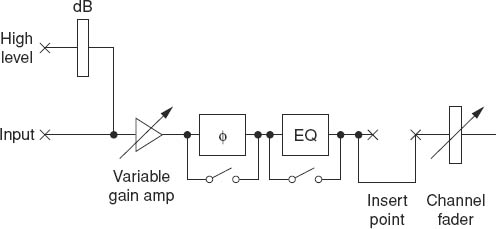
It may be helpful to refer to Figure 8.2 from time to time while reading this chapter. (The diagram is repeated so that you don't have to keep turning pages to look at it.) It is a block diagram; that is, it shows the relationship and connections between sections of the equipment but it does not give details of the circuitry.
There are a few points about Figure 8.2 which probably need clarification:
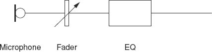
Figure 8.1 A much simplified section of a channel
1. The block marked ‘dB’ is simply a device which reduces the voltage of a high level signal to make it compatible with the microphone level input. (The term ‘high level’ is explained below.)
2. An arrow through a symbol means that the circuit represented is adjustable by some sort of control knob.
3. What is termed a ‘variable gain amp’ is an amplifier with a ‘volume control’. It constitutes the channel sensitivity control referred to later on p. 108.
4. The blocks marked φ and EQ have a switch below them. The idea of this is that the unit is bypassed, or switched out, when the switch is closed, thus making that unit inoperative.
5. An insert point allows other items of equipment to be connected into the channel. The two × symbols represent sockets. Insert points are not very likely to be found on the smallest mixers.
6. Not shown in the diagram, but important features of all but the smallest mixers, are ‘auxiliary outputs’. These are used for feeding such things as artificial reverberation devices and loudspeakers used for audiences. (The term ‘Public Address’ (PA), although not terribly accurate, is used for this.) Auxiliary outputs may be connected to the channel before the fader, or after it, or switchable from ‘pre-fader’ to ‘post-fader’. There's also a facility called ‘Foldback’, FB for short. This and PA will be explained further in Part 2 of this chapter.
7. A further point is that a practical mixer will have a number of amplifiers in each channel (and elsewhere). These are not shown in the diagram for the sake of simplicity.
How do we connect the sources to the mixer? In the case of a nonpermanent set-up the microphones and other sources will generally be plugged into the back of the mixer. This can be the cause of some confusion depending on what types of plugs and sockets are used. We go into this in a little more detail in Part 2 of the chapter. However, it is almost invariably the case that any mixer will have to cater for two types of source:
• ‘low-level’, sometimes called ‘mic-level’, sources; and
• ‘high-level’, sometimes called ‘line-level’, sources.
The difference between the two is a matter of the voltage output of the source. Low-level (mic-level) signals are just that – the sort of voltage which a typical microphone can deliver, and this is likely to be of the order of a millivolt (1/1000 V). High-level, or line-level, sources include tape and disc machines, and their outputs are probably going to approach 1 V, possibly more.
Expressed in decibels, low-level signals are typically in the range of –70 to –50 dB, relative to zero level (see Chapter 6, Part 2); high-level signals will be in the range from –20 to +10 dB.
It is important to make sure that a source is fed into the correct level input, not that any damage is likely to occur, but if the very small voltages from a microphone are fed into a high-level input the resulting output will be exceedingly weak. A high-level source fed into a low-level input will, almost without doubt, become very badly distorted.
To get round this problem, some mixers have two separate inputs for each channel, one for high level, one for low. On others there may be only one input for each channel but a switch (maybe a push-button) is used to select the appropriate level. Figure 8.2 shows two separate inputs. The block marked ‘dB’ represents what is known as an attenuator. It is essentially a system of resistances and its function is to reduce the voltage of the high-level signals to be comparable with those from, say, microphones.
Important features of any mixer
Channel sensitivity (or ‘gain’)
It is often necessary to make adjustments to the signal level from a source in addition to the high/low-level selection we have just mentioned. Different microphones may have different sensitivities, or compensation may have to be made for the loudness of the source. This could be handled with the fader, but it is often not convenient to do this for a reason which will be explained under the section headed ‘The fader’. A channel sensitivity control or ‘gain’ control is generally a small knob and may sometimes be concentric with a rotary fader, or it may be near the top of the mixer, furthest from the operator. (It's normal to position the controls which are used least furthest from the operator. This includes channel sensitivity controls. Faders, however, are used more often than anything else and are thus placed nearest to the operator.)
Phase reverse (symbol φ)
We have already mentioned the importance of correct phasing in the chapter on stereo. It can be important in mono as well. Imagine two similar microphones equidistant from a person speaking. If both are faded up then the combined outputs will cause an increase in level provided that they are wired correctly. If for some reason they are not, so that fading up both results in a cancellation effect (never in practice 100%), the combined signal is low in level and often sounds very ‘thin’ and ‘toppy’. The solution is to bring about a phase reverse somewhere, and a suitable switch or button can do this.
One argument may be that all equipment should be wired correctly so the problem should never arise. True, but just occasionally mistakes do occur. In practice, the most likely source of trouble is in the cables – more specifically in the connectors at the ends of the cables. It is all too easy for someone to make these up for a specific purpose and fail to get the phasing right. Also, some microphones do not conform to the European convention. Never assume a perfect world when it comes to wiring standards!
A further use for phase reverse switches, although not perhaps in channels, is to check that all is well during a rehearsal for a stereo recording. It is sometimes difficult to be sure that the phase as listened to on a loudspeaker is correct. A phase reversal in the feed to one loudspeaker can set the operator's mind at rest – or not!
Channel fader
This is the most important single control on the channel. It can be thought of as a volume control, as we have suggested, but on a proper mixer it will be much more accurately calibrated than is likely to be the case with a domestic hi-fi system. On small mixers the channel faders may be rotary controls. On large mixing consoles linear faders are used as these take up less space sideways, so that, say, twenty linear faders can be fitted into a unit 500 mm wide. A big advantage with linear faders is that several can be controlled simultaneously with one hand. They must, however, have a reasonably long ‘travel’ to allow accurate operation. The miniature sliders found on some domestic and semi-professional equipment are poor in this respect.
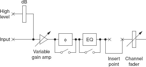
Figure 8.2 repeated
Fader calibration is likely to be reasonably accurate on all but the cheapest mixers. Some will have an arbitrary scale. Others, and these are to be preferred, will have a scale marked in decibels. In these a typical scale will be marked with numbers going from –∞ (minus infinity = fully faded out) through 0 to +10. The 0 position represents the setting at which, if all is correctly adjusted, the output from a professional mixer will be at about our old friend zero level. In other words, the 0 position is the normal working position, but there are several decibels ‘in hand’, meaning that the fader can be moved to appreciably higher settings if necessary. This matter of a ‘normal working position’ on a fader explains the reason for a channel sensitivity control. Any source can be adjusted until the mixer's output is at about zero level when the fader is set to 0 (or maybe 10). All stages of the electronics should then be operating so as to give optimum performance.
The scale on the fader, if it is marked in decibels, should be even, so that equal movements of the fader produce equal changes in the level in decibels. (Remember that equal changes in decibels result in roughly equal changes in loudness as judged by the ear.) At the bottom end of the scale, as –∞ is approached, the decibel increments can be much greater, as now the signal will be very low and a fade-out to (or a fade-up from) silence is what is wanted.
Equalization (EQ)
Almost any mixer, however modest, will have some EQ even if this is no more than a simple bass-cut control in each channel. On big and expensive mixers the range of EQ facilities may be very impressive and versatile. Here we shall deal with the basic types of EQ, the sort that might be found, not perhaps on the cheapest devices, but on medium cost units.
Briefly, the purpose of EQ is to modify the frequency response of a sound signal in order to:
1. ‘Clean up’ the signal. That is, to remove or at least reduce the worst effects of unwanted sounds such as traffic noise, rumble caused by wind blowing across the microphone, sibilance (excessive ‘sss’ sounds in speech), boominess from reverberation, etc. The list is almost endless.
2. Enhance or improve the clarity of the wanted sound by, for example, boosting certain parts of the frequency range.
3. Produce special effects. A good example is the simulation of telephone-quality speech in drama.
Before looking at the fundamental EQ controls, a word or two of clarification about the terminology may be helpful. Anyone with the slightest knowledge of music knows the terms ‘bass’ and ‘treble’, and these words are also used in relation to EQ controls. The difference in usage comes in the fact that, taking ‘treble’ as an example, instead of confining its use to the upper registers of voices or instruments, with an upper frequency of perhaps a few kilohertz, a treble EQ control could extend to 15 or more kilohertz. The terms as used in EQ are therefore much wider in their range than a musician might expect.
1. Bass cut or lift. This reduces or raises the bass content of the signal. Usually the control knob reduces the bass when turned anti-clockwise and increases when turned clockwise. Many good hi-fi units have a similar facility. Judicious use of bass cut can be valuable in, for instance, reducing traffic rumble and boominess caused by excessive reverberation in a hall.
Bass lift is much less useful but may on occasion be helpful when the sound quality seems ‘thin’, or perhaps the bass section of a choir could be improved with a little emphasis.
2. Top (treble) lift/cut. Top cut can be very helpful in reducing any hiss or sibilance. Top lift, like bass lift, is less useful but may go some way towards correcting ‘woolly’ sounds, or perhaps compensating for an incorrectly placed microphone.
3. Usually only found on the more expensive mixers is a presence control. This provides lift or cut to intermediate frequencies. The term originated some time in the 1960s, when it was found that raising a limited frequency band – around 2–3 kHz – by only a few decibels had the effect of making certain sources, vocalists in particular, sound nearer. (No one seems to have a very satisfactory explanation of why!) Lift can improve intelligibility of speech or give a little more impact to vocals. Cut can sometimes make unwanted mid-range sounds less conspicuous.
4. Bass and treble filters. These are like the cut controls mentioned above in 1 and 2, but they have a much more drastic action. A deep bass rumble may be almost eliminated by use of a bass filter.
More information about EQ controls is given in Part 2. What we must emphasize in the very strongest terms is that the decision to use any EQ should be made only after listening to its effect. It is all too easy to affect adversely a wanted sound when trying to reduce an unwanted one. Experience helps, of course, to shorten the amount of time spent in trials, and also some knowledge of what is going on can be valuable.
An example of this is trying to get rid of the buzz caused by having microphones and cables too close to fluorescent lights. This noise contains a very wide range of frequencies, from 50 or 100 Hz right up to several kilohertz, and it should be obvious that any of the EQ controls mentioned above are going, at best, to affect only a small part of the buzz's range. In other words, with that kind of unwanted noise, EQ is of little use.
Output stage
Then we come to the output section of the mixer represented in Figure 8.3. The lines coming in from the left represent the output of different channels. The meter on the right is labelled ‘PPM’ but it may of course be some other kind of meter, and in addition to the loudspeaker there may be, indeed almost certainly will be, a socket for headphones. The ‘fader’ before the loudspeaker is, in this case, a simple volume control.
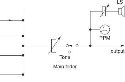
It should, of course, not be forgotten that in a stereo mixer all the components shown will be duplicated. We will explain the ‘tone’ switch in Part 2.
A famous and very highly respected manufacturer of professional mixers once produced a unit for mobile use in which the PPM was connected in error between the loudspeaker and its volume control. Quietening the loudspeaker also reduced the PPM reading. We leave it the reader to deduce why this was a mistake!
Questions
1. What is the main purpose of a channel sensitivity control?
a. |
To act as an additional fader |
b. |
To reduce distortion |
c. |
To allow the channel fader to be set to an optimum position |
d. |
To allow the channel to handle weak signals |
2. The symbol φ on a mixer indicates
a. The mains on/off switch |
b. Phase reverse control |
c. Phantom power switch |
d. Bass cut |