
10 Digital audio
Part 2
Compact discs
The vital component in a CD player is the laser, and without this it would be impossible either to make CDs or play from them. So what is a laser? It is, of course, a light source, but the light it emits is particularly pure in that it consists of one wavelength only. Ordinary light, as is well known, is made up of a wide range of wavelengths and this causes difficulties when the light is focused with a lens. The various wavelengths are treated slightly differently and this can be seen in the colour effects when one looks through an ordinary magnifying glass. The effect is particularly noticeable near the edges of the lens. Lenses for high-quality cameras are designed to reduce this chromatic aberration, as it is called, to acceptable levels. The beam from a laser, though, is so pure that it can be focused with extreme accuracy with quite a simple lens.
In making a CD, the light beam from a laser is modulated – that is, made to fluctuate in brightness – with the digital audio signal to be recorded and then focused upon the rotating master disc. A suitable material on the disc's surface is etched by the intense beam, producing a pattern of dots corresponding to the digital signal. Accurate copies of the master can be made by taking moulds and finally extruding plastic into the moulds. The process is not unlike that used to make traditional gramophone records.
In the replay machine, a low-power laser is focused on to the track and the light reflected back is detected and converted into electrical signals. After suitable decoding we end up with a very high quality audio signal. The optics of a CD player are shown in Figure 10.6.
The diffraction grating shown in the diagram is a device consisting of very many closely spaced engraved lines which act to produce separate images of the light passing through. (With white light, a grating of this sort creates spectral colours. These are easily seen when a CD is held at right angles to the light, the tracks on the disc acting as a grating. The same thing occurs with mother-of-pearl because of the existence of fine lines on the surface.)
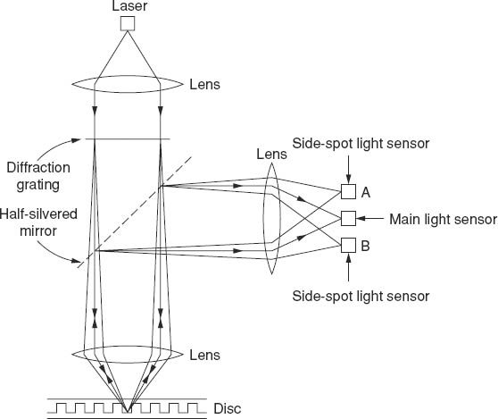
Figure 10.6 The optics of a CD player
The reason for putting in the diffraction grating is to produce additional beams which end up at the side-spot light sensors on the right. These are used to steer the laser beam over the disc's surface. A tendency to drift is shown by an increased signal in one of the side-spot sensors and a mechanical system returns the laser to the correct alignment. How the side-spots do this is shown in Figure 10.7.
To give some idea of the fineness of a CD's tracks, these are about 0.5 μm wide (0.5 of a millionth of a metre) and the centres of the tracks are 1.6 μm apart. In simpler terms, there are around 600 tracks to a millimetre.
To add to the facts and figures about CDs, the maximum playing time is about 75 minutes. The maximum replay time is always given as 74 minutes but in fact it can be a little longer than this. CDs with a playing time of 76 minutes are not uncommon! The length of the track is roughly 5.5 km, or just under 3.5 miles! The disc is made to rotate so that the scanning speed of the laser is constant. This means that the data are read out at a constant rate. To achieve this, the rotational speed has to vary from about 500 r.p.m. at the inside to 200 r.p.m at the outside. We put the figures in this order because the start is on the inside and the finish at the outside – opposite to a conventional vinyl record.
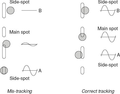
Figure 10.7 How the side-spots ensure correct tracking
Error correction
Some very powerful methods of detecting and correcting errors are incorporated into CD players. These are necessary because it is impossible to guarantee perfection in the manufacture of discs on a commercial basis. One has only to hold a CD, particularly one produced at least a few years ago, in front of a bright lamp bulb to see many tiny pinpoints of light. These may be very tiny – perhaps only one hundredth of a millimetre across in some cases, but even that would represent a significant loss of data. (It may be that the manufacture of CDs has improved. I get the impression that recent CDs I have bought show fewer pinpoints of light than those bought a few years ago. It could be, of course, that I'm just lucky!)
The writing speed, i.e. the speed of the track under the laser beam, is about 1.2 m/s. A hole only 1/100 mm in diameter is crossed by the beam in roughly 1/100 of a millisecond. Now we have already pointed out that a stereo digital signal requires nearly 1.5 million bits/second, so even this minute pinhole would account for somewhere in the region of 15 bits.
The full story of CD (and other digital) error detection and correction is beyond this book, but suffice it to say that a good player will compensate for ‘holes’ of up to 2 mm in diameter.
An experiment that may be tried is to take a felt-tip pen with washable, NOT permanent ink and draw a radial line across the disc. When the ink has dried, play the disc and if the line is thin – less than a millimetre across – there should be no audible effects. Then make the line wider in stages until the player either mutes or repeats a track. Finally, wipe off the lines and the disc will be as good as it was before! I have demonstrated this many times in front of audiences – who are generally very impressed. An outline explanation is given on p. 150.
IMPORTANT: neither the author nor the publishers can accept any responsibility if the experiment goes wrong.
We should add that this ability to correct for missing data requires many more bits than those just needed for the audio. By the time all the other data, some for timing, some for error correction, and so on, are taken into account the final bit rate is just over four million per second.
Cleaning CDs
There are some very attractive looking devices on the market for cleaning CDs. Rule 1, though, is don't get the disc dirty in the first place! Keep grubby – or even clean – fingers off the surface (not forgetting that the important surface is the non-label, or underside, of the disc).
If it should be necessary to clean a disc, a damp cloth wiped carefully across the tracks should do the trick. Smears along the line of the tracks could make it difficult for the system to read the data. This is why the washable ink pen in the experiment above is drawn radially – i.e. across the tracks.
Cost of CD players
There is little evidence to suggest that the sound quality from very expensive players is any better then that from much cheaper ones. There are likely to be more features on the costly ones, but whether these are important depends on the purchaser. In the early days of CDs, the error correction may have been better on the expensive machines, but this doesn't seem to be true any longer. Of greater significance is the way the extracted analogue signal is handled – the quality of the amplifiers, loudspeakers, etc.
NICAM
This stands for Near Instantaneous Companding Audio Multiplex, most of which we will try to explain! The form of NICAM used for stereo sound for television is the offspring of two separate technologies. The first, which we referred to briefly earlier, is a method of hiding the television sound signal (originally mono) in with the picture signal, so that only one signal path is needed from studios to transmitters.

Figure 10.8 A television line signal
Figure 10.8 shows a typical television line signal voltage – the higher the voltage, the brighter the line as it goes from left to right across the screen.
At the end of each line, the receiver has to be told exactly when to go back to the left and start a new line – it needs a synchronizing signal. This takes the form of the line sync pulse in the diagram, and the television sound signal in digital form is fitted in where the line sync pulse is, hence the term sound in syncs.
The complete signal is only sent in this way as far as the transmitters. Before going out to domestic receivers, the digital signal is removed and converted into an analogue form for transmission and the sync pulses are restored, otherwise receivers would have had trouble trying to synchronize the lines.
The original form of NICAM, the other parent technology, was a method of reducing the number of bits/second. It operated almost instantaneously (‘Near Instantaneous’) and worked to compress the number of bits, later expanding the number when it was appropriate to do so. This process of compression with subsequent expansion is known as companding. The A in NICAM stands for audio – well it would, wouldn't it? – and multiplexing means combining signals together. Hence NICAM.
Stereo NICAM for television is a very ingenious method of taking stereo sound signals in digital form, applying a companding process to have a manageable number of bits, and fitting the result into the video waveform as a new form of sound in syncs. This happens as far as the transmitters. There, the stereo signal is fitted into a section of the transmitted television signal and it reaches the NICAM-equipped receivers in this form. For the benefit of non-NICAM receivers, an analogue mono version is produced at the transmitters and transmitted in the normal way.
Besides being stereo, the digital quality is much better than ordinary television sound, although not quite as good as CD quality, despite what has been claimed in some advertisements.
A little more about error correction
The reader who tried, or was tempted to try, the experiment with a water-based felt-tip pen and make marks across a CD may have wondered how the gaps were made inaudible.
With almost any digital recording system the blocks of data – that is, the 1s and 0s making up a sample – are scattered according to a universally accepted code. This is shown in Figure 10.9. The top line represents the original data in their correct order. The middle line shows the effect of scattering, while the bottom line is the data put back in their correct order.
Now suppose there has been a major loss of data – perhaps caused by a pinhole-sized gap on the disc, or some idiot drawing radial lines with a pen! This is shown by the dotted rectangle, and data blocks D, H and M are lost. However, after re-assembly, these lost blocks are well dispersed and provided there isn't too much lost, various parity checks can go a long way towards ‘filling in’ the missing data.
