
6 Monitoring
Part 1
Monitoring in an audio context means keeping a careful check on the sound signal. There are two broad requirements. One, visual monitoring, can be regarded as technical – that the signal voltage keeps within prescribed limits for reasons which will be explained. The second, aural monitoring, uses the operator's ears not only to listen for technical imperfections which cannot be shown easily (if at all) by visual means, but also to fulfil what is at least partly an artistic function – that the balance, perspective, performance and so on are satisfactory. We will take these in turn.
Technical monitoring
To understand properly the need for this, we must first consider dynamic ranges – the difference in dB between the loudest and the quietest signals. Of all the likely sound sources, a symphony orchestra probably has one of the widest dynamic ranges. Table 2.1 in Chapter 2 shows that an orchestra produces a maximum sound level in excess of 100–120 dB(A) at peaks – but there may well be bars in the music which require all instruments to stop playing and the sound level in a quiet studio may then be less than 20 dB(A). The dynamic range of an orchestra is thus likely to be about 100 dB – possibly even more.
DEFINITION
Dynamic range is the difference in dB between the loudest and the quietest audio signals.
The dynamic ranges of other programme sources are generally much less. Normal speech, for instance, may well be contained within 30 dB.
It is important to remember that all items of audio equipment – microphones, recording machines, amplifiers, loudspeakers and so on – have their own electrical limitations. If the signal level is too high, there will be distortion because the equipment cannot handle these voltages – and there may even be a risk of damage in some cases. At the other end of the scale, there is a background hiss which arises because, to take one reason, electricity consists of individual particles – electrons – and is not a smooth stream of something like water. While we can generally pretend that electricity is a continuous fluid, because light bulbs do not flicker because of the particle nature of the current, when it comes to very small currents which are going to be amplified the fact that electrons are not continuous can begin to show up. This is a matter of great importance, for example, in detecting the faint signals in radio astronomy, and special techniques have to be adopted.
With analogue magnetic recording there is another source of hiss due to the fact that the magnetic material on the tape is made up of particles of magnetic material – particles again! With digital recording systems, as we shall see, the effects of tape hiss are eliminated.
The dynamic range, or signal-to-noise ratio, which we shall take to be the same thing, on conventional audio cassettes depends on the tape quality, but 50 dB is a reasonable figure, if perhaps a little optimistic. As we explain later, this can be extended by noise reduction systems, but the fact remains that the range is very much less than that needed for a symphony orchestra. Even a compact disc's dynamic range is not infinite, but being in the region of 90–100 dB is probably good enough for all practical purposes.
If we think about rock music, although the dynamic range may be fairly small (from very loud at minimum to exceedingly loud at maximum!), there is still the problem of avoiding high signal levels which could cause distortion.
How the dynamic range of a sound source is reduced to ‘fit’ in the signal-to-noise ratio of the system is something that we shall deal with later, but it is enough at the moment to realize that it is vitally important for any operator to know whether or not the signal being dealt with is within the limits of the system.
Of course, there are two limits, an upper and a lower, and of the two the upper one is the more important for the simple reason that this represents the loud end and if distortion occurs it is going to be very apparent and unpleasant. Therefore, a means of detecting the programme peaks is crucial.
Let us say straight away that the ear is useless for this purpose. To begin with, the sound level coming out of a loudspeaker is affected by the setting of the volume control. Secondly, the ear adjusts to sound levels and what might seem loud to start with becomes a more comfortable level after a few minutes. Furthermore, our judgements of loudness tend to be affected by whether or not we like the music or are interested in the content of the programme. Folk music at a very moderate volume can be excruciatingly loud to someone whose taste is for classical music.
There is thus a need for some kind of electrical measuring device.
There are two broad categories of measuring device that are in widespread use. They are outlined here, but more technical information is given in Part 2 of the chapter.
1. More or less conventional voltmeters
These may not look like voltmeters because of their possibly unusual scales. The best-known example is the VU meter, VU standing for volume unit. This is found on much professional equipment and a form of it, with perhaps less rigid specifications, may be seen on the slightly more expensive domestic cassette recorders, although the latter are now more commonly fitted with LED indicating systems (see section 3 below).
The VU meter is reliable and relatively cheap, but it has a major drawback in that it indicates average voltages, whereas it is the peaks that are the really important things to be monitored, as we have shown.
2. Peak indicating meters
Basically, these are devices with electronic circuitry which detects and holds the voltage peaks long enough for them to be registered by the meter pointer, or some other indicator. The best-known example, at least in the professional field, is the Peak Programme Meter (PPM).
Because the circuitry is relatively expensive (particularly so in the case of stereo versions, which have two pointers with concentric spindles), these are generally only found in fairly costly equipment. However, if equipment is to be hired or borrowed, that which is equipped with PPMs should be preferred.
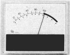
Figure 6.1 VU meter (courtesy SIFAM Ltd)
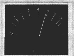
Figure 6.2 PPM (Peak Programme Meter) (courtesy SIFAM Ltd)
The true PPM has a black scale with white numerals and the pointer is controlled in such a way that it has a very rapid rise time and a much slower fall-back, these characteristics making it easier to read the signal peaks but adding, of course, to the cost. Considered all round, the PPM is much superior to the VU meter, as it can indicate with adequate accuracy the all-important signal peaks and thus warn of impending distortion.
VU Meter – Essentially a meter which shows average programme voltages.
PPM – A meter which indicates the peak signal voltages. The scale is black with a white pointer, which has a rapid rise and slow decay.
3. LED indicators
Coming really into category 2 above, but dealt with separately here for convenience, is a range of relatively low-cost devices using LEDs (light-emitting diodes). These are much less accurate than PPMs, or even VU meters, but they can be made to give a fair indication of signal peaks using what is sometimes called the ‘bouncing ball’ technique. The electronics associated with the display allow the highest LED segment to stay lit for a second or so after the peak has passed. This can be a very adequate means of monitoring audio signals, although it is much less precise than a PPM. PPMs can be read to an accuracy of 0.5 dB with a little practice, whereas the individual segments of an LED unit are frequently arranged in steps of 2 or even 3 dB. For many purposes, though, this may not matter. I have to say that, personally, I prefer to monitor a recording with a peak indicating LED display rather than with a VU meter, assuming no PPMs were available.
Aural monitoring
For a human being's ears to assess the quality of a sound signal, there needs to be, first of all, good quality listening equipment – headphones or loudspeakers. To begin with, let us state that of the two, loudspeakers are considered by almost all experienced sound engineers to give much better indications of quality than headphones.
The reasons for this are not always very clear. One thing is certainly true: stereo image positions given by headphones do not in general correspond at all well with those produced by loudspeakers – and that loudspeaker stereo images can relate well to the sound sources in front of the microphones.
Of course, it has to be admitted that there are many situations where loudspeakers cannot be used and therefore headphones are the only practical alternative – outdoor location work being one example. One other drawback with headphones is that they tend to isolate the wearer, not just acoustically (which might not always be a bad thing) but also psychologically, from other members of the team. Apart from all else, in studio-type situations the headphone wearer may find it difficult to hear comments or instructions from others, although ‘in-ear monitoring’ with small earpieces avoids this problem.
We will begin, then, by considering loudspeakers.
Loudspeakers
The main requirements of a loudspeaker are that it can handle with equal impartiality all the frequencies in the region from 30 Hz to about 16 kHz. It should also be able to produce relatively high sound levels if necessary. Notice that the low frequency end is given here as 30 Hz not the 16 Hz stated in Chapter 2 as being the lower frequency that the normal car can detect. The point is that it has been, and to some extent still is, difficult to make audio equipment operate satisfactorily below about 30 Hz. Luckily there are relatively few sounds of any importance in the range 16–30 Hz, large pipe organs being an occasional exception. Furthermore, the human ear/brain combination has the ability to compensate to some extent for missing bass frequencies (‘False bass’, referred to on p. 23). Consequently, broadcasters and recording companies have, for a long time, accepted that 30 Hz is a reasonable lower limit in practice, although the increasing use of digital recording equipment removes one (but only one) of the obstacles to really deep bass reproduction.
The requirements in terms of sound levels vary with the situation. A professional studio is likely to want loudspeakers that can produce sound levels in the region of 120 dB(A) at 1 m. Such loudspeakers are large and/or expensive. They can also be a severe hearing hazard! For semiprofessional and serious amateur work, the requirement can be much more modest. Maximum sound levels of perhaps no more than 80 dB(A) at 1 m are likely to be perfectly adequate, and such levels are well within the range of relatively small and modestly priced units.
Basic loudspeaker construction
A loudspeaker is, in a way, a microphone ‘working backwards’ and it may not be surprising therefore to find that the most commonly used loudspeakers have features in common with some microphones. In fact, many loudspeaker units can function as microphones and indeed do so in some intercom systems. In place of the microphone's diaphragm, a loudspeaker has a cone which is made to vibrate and thus generate sound waves.
A favoured material in low cost cones is a form of compressed paper. This can be fairly satisfactory but it may not be easy to achieve a good match between two units – essential for stereo reproduction – because of differences in the orientation of the fibres in the material. Modern high-quality loudspeakers have cones made of vacuum moulded plastic – polypropylene being a good example.
In principle, many systems can be used for the loudspeaker transducer. The one most commonly used is a moving coil unit, as shown in Figure 6.3. This is very similar to a moving coil microphone transducer, except that in a loudspeaker the coil and magnet are much larger.
The reason for the popularity of the moving coil unit is that, in conjunction with a suitable cone and appropriate enclosure (see below), it can cover a reasonably wide frequency range and at the same time handle power levels which are adequate for many purposes. This is not to say that a single such unit can meet the requirements set out above, but with good design it is possible to cover almost the full frequency range and produce quite high sound levels with two or at most three units in one enclosure.

Figure 6.3 Moving coil loudspeaker unit
Other transducer devices besides moving coils find application in, for example, certain ‘tweeters’ (see below).
The combination of transducer and cone is almost invariably an integral unit. A frequently used term for the combination is ‘drive unit’.
Drive unit – Term used to mean the combination of transducer and cone.
The remaining major component in a loudspeaker is the enclosure or cabinet in which the drive units are mounted. This is much more than just a box and a good loudspeaker depends heavily on a well-designed enclosure.
To summarize the reasons for the need for a good enclosure, a drive unit on its own radiates sound waves from both the front and rear surfaces of the cone. Imagine that the cone moves forward: a sound wave compression is emitted from the front but a rarefaction (low pressure) wave emanates from the rear. If the wavelength is large, these two sets of waves will diffract round the cone and tend to cancel each other out – the low pressure ‘swallowing up’ the high pressure. At high frequencies, when the wavelength is small, this diffraction does not occur so that the front and rear waves tend to travel outwards in something approaching straight beams. This means that a listener on the front axis of an isolated drive unit will receive sounds which are seriously lacking in bass frequencies because these have largely cancelled themselves out. Figure 6.4 shows the approximate frequency response of a 25 cm cone unmounted in any kind of enclosure.
A solution, although not necessarily the best one, is to put the drive unit in a sealed box, as shown in Figure 6.5. Obviously, this prevents any sound waves from the back of the cone coming round to the front.
The inside of the box needs to be treated with sound-absorbent material to reduce internal reflections of sound waves, and the box should be made of rigid but non-vibrating material. Chipboard can be satisfactory but birch ply has been found to be excellent in some professional loudspeakers.

Figure 6.4 Response of an unmounted cone
Finally, it is possible for the complete unit to be compact. A typical volume is around 0.01 m3 (e.g. 30 cm high, 20 cm wide and 15 cm deep).
Unfortunately, sealing the box in this way has an effect similar to holding a finger over the end of a bicycle pump, when it then becomes difficult to operate the pump. In the same way the cone movements, which at low frequencies have to be relatively large to generate the required volume of sound, are restricted. Hence the bass response is then not as good as one might perhaps have hoped for, although it can still be very respectable – and even good enough for some professional purposes.
Figure 6.6 shows a more ambitious design – the vented enclosure, sometimes called a ‘bass reflex’ cabinet. The idea is that the vent and the rest of the cabinet form a device called a Helmholtz resonator, designed in this case to have a natural frequency of acoustic vibration in the region of 30 Hz. Careful choice of the dimensions of the unit allow it to be ‘tuned’ to a frequency which boosts the drive unit's output where it would otherwise be falling off. Vented loudspeakers are usually rather large, heavy and expensive, but they can give both very good sound quality and high sound levels. They are almost invariably the first choice for professional studio monitoring.

Figure 6.5 Sealed enclosure loudspeaker
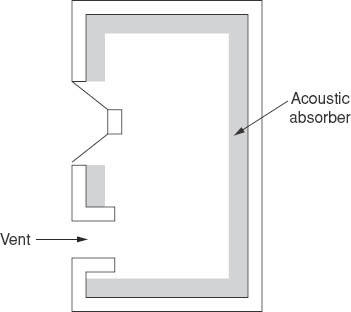
Figure 6.6 Vented loudspeaker enclosure
Multiple unit loudspeakers
It is impossible for a single drive unit to cover the full audio range and at the same time produce high sound levels. Designers therefore resort to the use of more than one unit in the cabinet. Typically, there is a bass unit which covers the frequency range from 30 Hz up to perhaps about 800 Hz; a mid-frequency unit, going from there up to around 3 kHz, and finally a tweeter, which takes over and extends the range to 15–16 kHz. An electrical circuit called a crossover network divides the audio signal into the required bands.
On some high-grade professional monitoring loudspeakers, careful design has made it possible to cover the full range using only two drive units. This simplifies greatly the design (and cost) of the crossover network.
A drawback with large multiple-unit loudspeakers is that, because of the spacing of the units, an operator has to be a little distance – perhaps a couple of metres – away from the loudspeaker. Sometimes this may not be a problem, but when space is limited loudspeakers with minimal spacing of the units are needed so that a good balance between the different sound components is achieved quite near to the loudspeaker. These are often referred to as near-field monitors.
Finally, it may be worth pointing out that the sound one hears from a loudspeaker is very much influenced by the listening environment, and it can be argued that this environment should be similar to the final ‘customer's’ listening conditions. This is obviously an impossible requirement as there are going to be almost as many different such conditions as there are customers. Nevertheless, a step in this direction has been taken by a number of manufacturers of television broadcasting sound mixing consoles. They have incorporated a small domestic listening speaker. The programme sound can be switched away from the main high-quality units to these small ones, and this can give an indication of the sound which will be emitted from a typical domestic television set.
Headphones
As far as their construction goes, it is simplest to regard these as miniature loudspeakers. Many, but not all, use moving coil units and in a way headphone design is easier than for loudspeakers because the power requirements are less. In other words, a single unit can produce adequate sound levels and a wide frequency range at the same time – which is not to say that they all do! Choice is very much a matter of cost (headphones being vastly cheaper than loudspeakers of corresponding quality) and comfort.
Listening tests
We will end this chapter with a topic whose importance cannot be stressed too greatly. Any listening test designed to make a comparison between two items of equipment must be done by direct switching between the two – what is often termed A–B comparison.
The point is that the ear's memory for really accurate recall is short: 1–2 seconds. It is quite impossible therefore to listen to, for example, a good loudspeaker on Monday and then decide that another good one, heard on Tuesday, is better or worse. This kind of comparison may well be feasible if one loudspeaker is good and the other is poor, but assuming that the two are of comparable quality then immediate comparison is the only answer. And this applies to amplifiers, cassette machines, microphones, CD players, the lot. A moment's thought shows that A–B tests are sometimes not very easy to arrange. How would we compare two CD players? We'd have to make sure that each had the same edition of the disc on it (sometimes a record company issues more than one version of the same original; the differences may be very slight indeed, but they might be there). Then the players would have to be connected to the same amplifiers and thence to the same speakers. The discs would need to be cued up so that they are running as closely in step as possible. A switch, preferably clickless, is needed to switch one CD player at a time to the amplifier. And to finish off, the listeners ought not to be aware of which CD player is in use at any one time; the switching must be done randomly and preferably with more than one type of music. Only then can one make a proper judgement! If there are more than two items to be compared, these must be done in pairs. Attempting to make comparison between three or more sounds is very difficult indeed.
The reader is advised to be very wary of statements like ‘This amplifier doesn't sound as good as the one I heard at so-and-so's house last week’. Sadly, one has found this sort of thing in the hi-fi press! And I have to say that I'm very sceptical about reviews which talk about the ‘musicality’ of equipment – amplifiers, CD players and so on.
Questions
1. Which statement is correct about VU meters? They indicate
a. Loudness |
c. Average signal voltages |
b. Sound power |
d. Peak signal voltages |
2. Which statement is correct about PPMs? They indicate
a. Loudness |
c. Average signal voltages |
b. Sound power |
d. Peak signal voltages |
3. A–B comparisons of two separate sound devices are necessary because the ear's memory for accurate recall of sounds is around
a. 1 ms |
b. 100 ms c. |
1–2 seconds |
d. 10–20 seconds |