
Now, there are entire books written about statechart theory and so we won't even attempt to cover the entire topic in this small section, but that's fine. Like with most software development concepts, we can begin to apply the theory without having to know it all upfront. For our needs, we just need to recognize and remember the proper patterns and let time and practice make the theory clear to us.
Statecharts is a graphical language developed by professor David Harel that has been gaining popularity steadily due to its usefulness in modeling reactive systems. Using a statechart, we can design our application as a series of finite states that will respond (or not respond as it may be) to the many events and actions that occur. In this way, every possible function of our application can be described before being translated directly into code.
It's probably best to begin with an example diagram. The following is a simple statechart one might start with for an application:
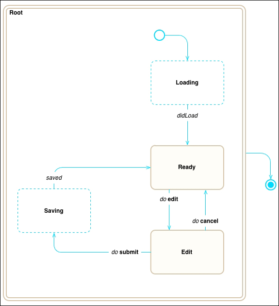
This application has five states: Loading, Ready, Edit, and Saving that are all substates of the Root state. In a statechart there is always one root state that has no parent.
While all of these states are technically equivalent, I've drawn the Loading and Saving states using a dashed line to reflect that these are transition states, which simply means that the application won't accept any user input while in these states. I've also drawn the Root state using a double line, to reflect that it has substates. If I had outlined any of the other states with a double line, you would know that state has substates within it, which, in order to keep the diagram easy-to-read, would be shown in a further diagram. There are also two special non-states, which I've drawn with circles. At the top of the diagram is the default entry point to the Root state, which is shown as an open circle and to the rightmost there is the end point for the entire statechart, which is shown as a circle within a circle.
Finally, there are the most important components to the diagram, the state transition arrows. These arrows tell us exactly how our application will change state and to which state it will change. To differentiate between events (things that happen) and actions (things that the user triggers), I've drawn the events in italics and the actions in bold. Having our state transition arrows properly defined gives us the entire picture of how our application will behave. For instance, while in the Loading state only the didLoad event will transition to the Ready state. From there if the user invokes the edit action, the application will transition to the Edit state, where the user may invoke either submit or cancel. As well, at any state inside the entire Root state, the user may just close the browser, which is shown as an arrow leaving the Root state to the statechart's endpoint.
The whole diagram is incredibly simple and yet incredibly powerful when put into use. I realize that may seem like a stretch at this point, but I'm sure that even this simple statechart implemented in code would have a profound effect on the robustness of the application. The reason, this is because we're effectively locking down much of how our application functions. Consider this for example, if we had used an isSaving flag we would have to remember to check the value of that flag each time the user clicks on edit, submit or cancel. If we didn't check it or the flag was toggled at the wrong time (race condition), we might accidentally double submit or edit the wrong object. Of course, you would likely disable the respective buttons in the UI based on the isSaving flag, but remember that not all actions are always triggered through the user interface. It's simple for someone with malicious intent to open the browser console and try calling improper actions. With our statechart though, we can clearly see that while in the Saving state, none of those actions can occur.
Before we move on, I'd like to introduce a bit more of the statechart theory and expand on what we've seen so far. The first addition is to add history to the default entry point. The concept here is that upon entering a state with substates, we often want to go to the previously entered substate. For example, in a chess game we would have a Match state for an active match with two substates WhitePlays and BlackPlays. When we start a new match, the application would go to the Match state, which would always enter its WhitePlays substate the first time. However, after this point if we left the Match state and re-entered it, we would not want to go directly to WhitePlays, but to whichever substate we were previously in. To do so, we would enter the history state for the Match state, which is represented by a circle with an H as shown in the following diagram:
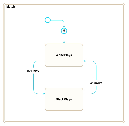
Just as we described, the default entry point is to the history state (one of either WhitePlays or BlackPlays) and as you can tell by the arrow from the H to WhitePlays, if there is no history state, it would go to the WhitePlays state by default.
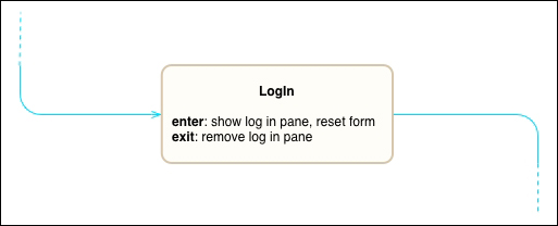
We can also add more detail to our diagram to reflect how states are entered and exited. Remember that statecharts is a graphical language that will later be translated directly into code; so the more we capture upfront, the less we leave up to interpretation later.
First off, entering and exiting a state will usually perform certain actions, which we can make note of in the diagram. For example, if we were to use a LogIn state, we could include actions to present the log in pane and clear the form on entry and to also remove the pane on exit.
Next, event transitions are often dependent on conditions, such as the body of the event or whether the event represents a success or failure. In these cases, the same event type may result in different state transitions according to the event's properties. We can show such conditions in the diagram by including them along with the event name. For instance, every server response may succeed (for example, HTTP 200 OK) or may fail (for example, HTTP 403 Forbidden) and so a more complete version of the Saving state from the first example could be the following diagram:
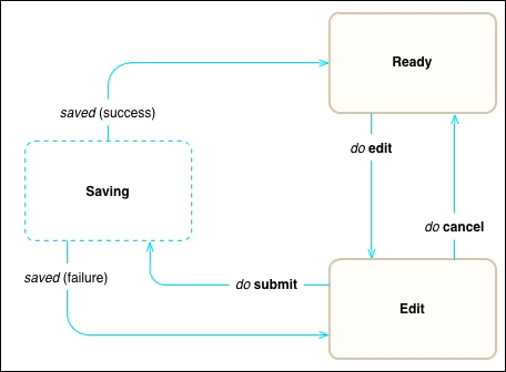
Notice that the saved event now contains the success or fail condition in parenthesis. This value indicates the two ways that the saved event will be handled.
While the statecharts language allows for further ways to structure the diagram for readability, we have now captured all of the core features of a statechart with the exception of one, concurrency.
The statecharts language also provides for concurrent states, which allow the statechart to be in multiple states at the same time. On the surface, this doesn't seem overly complex, but it actually adds too many new variables to the discussion to be within the scope of this book. Because concurrent states are more difficult to diagram and to use correctly, I would recommend avoiding them until you have much more experience with the language.