Appendix A – Cruise Control
TABLE OF CONTENTS
1. Background
2. Context Schema
3. Event List
4. Preliminary Transformation Schema
5. Leveled Set of Schemas
6. Data Dictionary
7. Transformation Specifications
Problem Statement
The ordinary household thermostat performs “closed loop control” – given a desired temperature setting, it monitors the actual room temperature and turns the heat on and off to keep actual temperature close to desired temperature. In maintaining a desired speed, the driver of an automobile does something quite similar; he or she monitors the actual speed by watching the speedometer, and depresses or releases the accelerator pedal to keep actual speed close to desired speed. A cruise control system relieves the driver of the responsibility for maintaining speed by taking over the closed loop control. The system described here is an “add-on,” which is installed after the automobile is purchased.
The Cruise Control System operates only when the engine is running, and is automatically reset to its “off” status when the engine is started. When the driver turns the system on, the speed at which the car is traveling at that instant is maintained. The system monitors the car’s speed by sensing the rate at which the wheels are turning and maintains desired speed by monitoring and controlling the throttle position, as shown by Figure A.BKG. The monitoring is accomplished by a sensor that produces a signal proportional to the throttle’s position. The control is exercised by changing the degree of openness of a valve, which in turn controls a suction apparatus that draws on a chain to open the throttle. The throttle closes itself when not being actively controlled. After the system has been turned on, the driver may tell it to “start increasing speed,” which causes the system to increase the speed at a fixed rate. When the driver tells the system to “stop increasing speed,” it will maintain the speed reached at that point.
Of course, the driver may turn the system off at any time. In addition, the driver can override the system to increase speed simply by depressing the accelerator pedal. As indicated by Figure A.BKG, this causes the chain controlling the throttle to go limp. During the period of greater speed, the system continues to attempt to maintain the speed previously set, and the system will return the car to the previous speed when the driver releases the pedal. If the system is on and senses that the brake pedal has been depressed, it will cease maintaining speed but will not turn off. The driver may subsequently tell the system to resume speed (provided it hasn’t been turned off in the interim), whereupon it will return at a fixed rate to the speed it was maintaining before braking and resume maintenance of that speed.
The speedometers on many cars are inaccurate, and so this system incorporates its own speedometer. However, the speedometer must be calibrated when installed on a particular car. Since cars have tires of various sizes, the mileage equivalent of one wheel rotation can vary. The system thus accepts “start measured mile” and “stop measured mile” instructions, and resets its conversion factors to correspond to the number of wheel rotations sensed within the time period of the measured mile. This can only be done with the cruise control in “off” status.
Figure A.BKG Cruise Control.

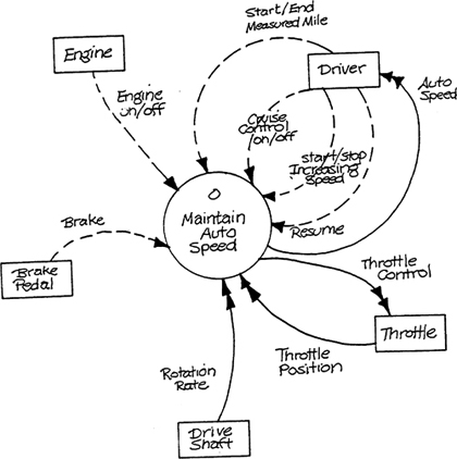
Figure A.CS Context Schema.
Event List
Engine starts up.
Engine shuts down.
Driver requests maintenance of current speed.
Driver requests start of speed increase.
Driver requests end of speed increase.
Driver requests termination of speed maintenance.
Driver indicates start of measured mile.
Driver indicates end of measured mile.
Brake pedal is depressed.
Driver requests resumption of maintenance of previous speed after braking.
Speed reaches previous value after braking.
Figure A.PTS Preliminary Transformation Schema.

Figure A.0 Maintain Auto Speed.

Figure A.1 Monitor Engine.

Figure A.2 Maintain Active Status.

Figure A.2.1 Determine Mode of Operation.

Figure A.2.2 Manage Control Mode.

Figure A.2.2.1 Control Cruise Control Engagement.

Figure A.2.3 Manage Learning Mode.
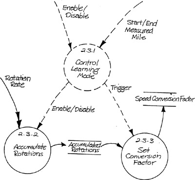
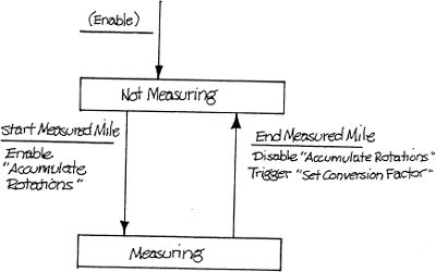
Figure A.2.3.1 Control Learning Mode.
Data Dictionary
Transformation Specifications
2.2.2 Record Rotation Rate
Precondition 1
None
Postcondition 1
Post ROTATION RATE in ROTATION RATE SETPOINT
2.2.3 Increase Speed
Precondition 1
None
Postcondition 1
THROTTLE POSITION at < 80% of max. – Instantaneous rate of increase per second of ROTATION RATE maintained at 2% ± .25% of current value of ROTATION RATE
For THROTTLE POSITION at ≥ 80% of max. – Instantaneous rate of increase per second of ROTATION RATE maintained at 0.
2.2.4 Maintain Constant Speed
Precondition 1
ROTATION RATE within 1% of ROTATION RATE SETPOINT
Postcondition 1
For time ≤ 0.5 seconds after enable, match THROTTLE CONTROL to THROTTLE POSITION
For time > 0.5 seconds after enable, maintain ROTATION RATE within 1% of ROTATION RATE SETPOINT
2.2.5 Return to Previous Speed
Precondition 1
None
Postcondition 1
For time ≤ 0.5 seconds after enable, match THROTTLE CONTROL to THROTTLE POSITION
For time > 0.5 seconds after enable, maintain rate of increase per second of ROTATION RATE at 0.1* (ROTATION RATE SETPOINT – ROTATION RATE)
2.3.2 Accumulate Rotations
Precondition 1
ACCUMULATED ROTATIONS = 0
Postcondition 1
ACCUMULATED ROTATIONS = ![]() Rotation Rate dt
Rotation Rate dt
2.3.3 Set Conversion Factor
Precondition 1
None
Postcondition 1
SPEED CONVERSION FACTOR = ACCUMULATED ROTATIONS
2.4 Report Current Speed
Precondition 1
None
Postcondition 1
AUTO SPEED = ROTATION RATE/(SPEED CONVERSION FACTOR * 3600)