
4
Deriving the Behavioral Model
4.1 Introduction
The context schema and its associated specifics, together with the external event list and the environmental data schema, if one is built, constitute a detailed model of a system’s environment. Clearly this model does not contain all the details necessary to build a detailed description of the system’s behavior. Nevertheless, the environmental model provides a basis for constructing the behavioral model, and in this chapter we lay out the guidelines for doing so.
4.2 An Informal High-Level Requirements Model
Our task in building the behavioral model is very simple: We must describe the response made by the system to each event in the external event list. A very direct way of approaching this assignment is to describe the responses informally in narrative text. The results can be organized in the form of a two-column list that shows each event in the left-hand column and the corresponding response in the right-hand column. The description of the response must include at least:
![]() the most common or most likely response to the event;
the most common or most likely response to the event;
![]() alternate responses and the conditions under which they are made; and
alternate responses and the conditions under which they are made; and
![]() conditions under which the system will not respond to the event.
conditions under which the system will not respond to the event.
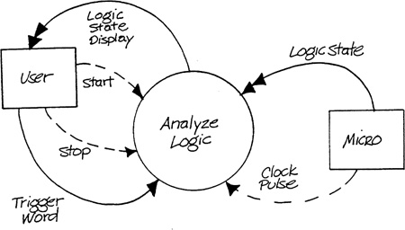
A package that includes a context schema, a statement of purpose, and a list of events with narrative response descriptions is a very useful informal specification of requirements. It could be considered as a preliminary deliverable for purposes of project management. In addition, it might be the only system description necessary for high-level review and “sign-off” by managers who need only understand the system in general terms. An example of a package of this type for the SILLY system would include Table 4.1 along with Figure 4.1.
Clearly the package just described is not a rigorous specification of the behavior of the proposed system. There is no information, for instance, on the use of the system inputs shown on the context schema by the various event responses. In addition, there are no rigorous criteria for deciding whether a response is satisfactory, such as required quantitative relationships between output values and corresponding input values. To fill in these details, a notation more formal than narrative text must be used to specify the responses. We shall, of course, use the transformation schema and data schema.
Table 4.1 Informal Requirements Model Events and Responses.

Figure 4.1 Informal Requirements Model – Context Schema.
4.3 Systems Dominated by a Specific Perspective
We showed in Chapters 6 and 10 of Volume 1 that there are two fundamentally different perspectives one can take in describing a system. The active view, which we expressed by the transformation schema, pictures the system as a mechanism for transforming inputs into outputs. The passive view, for which we used the data schema, sees a system in terms of the associations among real-world things that it must keep track of. All systems that are built from computer hardware and software components transform inputs into outputs, and virtually all systems need to create or remember data about their environments. However, the relative importance of these two aspects varies widely from system to system.
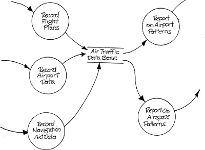
Imagine a system that collects data about the flight plans filed by all the aircraft over a large region, and uses this data to derive statistics about arrival and departure patterns at particular airports by time of day or by type of aircraft, traffic densities in various regions of the airspace, and so on. The transformation schema of Figure 4.2 illustrates such a system in general terms. Notice that the transformation structure of this system follows a pattern that is typical of all data storage and retrieval systems; it consists of one group of transformations that puts data into storage, and another group that extracts stored data and creates outputs. The focus of the storage transformations will be on the patterns and validation rules of data as it arrives from the reporting sources, and the focus of the retrieval transformations will be on identifying specific data associations and transforming them into outputs.
Figure 4.2 Air Traffic Analysis System Transformation Schema.
This perspective is not as broad nor as illuminating as the structure of real-world associations between aircraft, airports, runways, navigation markers, and so on that constitutes the basic subject matter of the system and that is illustrated in Figure 4.3. Therefore, a data schema should be of more assistance to the developer for this type of system than a transformation schema. It is fair to call systems of this type stored-data-driven.
Figure 4.3 Data Schema for Figure 4.2.

Pure data storage and retrieval systems, of course, don’t typically fall into the real-time category. However, a process control system with rather modest control requirements may have elaborate requirements for collecting, correlating, and analyzing data about the processes controlled. Such a system might also be stored-data-driven.
In contrast, consider the bottling system described in Appendix B and shown in simplified form in Figure 4.4. In a mechanical sense the world surrounding the embedded system might have quite an elaborate structure – the bottle-handling machinery and the liquid flow connections between the storage tank and the filling valves might be quite complex. However, many of these complexities are irrelevant to the system as it performs its specific functions of controlling pH, opening and closing valves, and so on. The real-world associations that the system must keep track of are less illuminating to the developer than its operations – the patterns by which it transforms continuous inputs into continuous outputs. This type of system is characterized as transformation-driven.
Figure 4.4 Bottling Filling System (Partial).

There is a large class of systems for which the data schema and the transformation schema are about equally important in terms of the insight that they provide for the modeler. But in cases where one view or the other is dominant, an early focus on the dominant view should facilitate the development process.
The event list can be used to decide whether the data schema or the transformation schema is likely to dominate. A stored-data-driven system has events that fall into one of two categories. The first category is a real-world event to which the system responds by storing data. In the air traffic analysis system of Figures 4.2 and 4.3 such events might be Pilot Files Flight Plan, Airport Changes Landing Pattern, or Navigation Marker Relocated. The second category consists of requests for analytical data in which the inputs (if any) simply identify the stored data to be extracted and manipulated. An event of this type might be Analysis of Airport Arrival Pattern is Requested.
The majority of events in a transformation-driven system will require a response that uses current inputs to produce immediate outputs and store data only incidentally. In the bottle-filling case, such events are Operator Initiates pH Control (by starting the system, for example) and Bottle Arrives at Filling Valve.
A system developer can examine the event list for events fitting these descriptions and use this information to decide whether to build the transformation schema first, to build the data schema first, or to build both schemas together. In the remaining sections of this chapter we will address first the building of the transformation schema and then the building of the data schema.
4.4 Representing Behavior on the Transformation Schema
Required behavior can often be represented on the transformation schema in either data transformation or state transition terms. Consider the event Quantity of Inventory Item is Issued in relation to the system modeled in Figures 1.5, 1.6, and 1.7 Chapter 1. If the state transition representation (Figure 1.6) is chosen, an inventory issue that drives the quantity to zero will cause a change of state and will prevent the system from responding to future issues of that item until a receipt occurs. In fact, the event list should include Item Goes out of Stock, an event that requires an indirect recognition mechanism. On the other hand, if the data transformation representation (Figure 1.7) is chosen, no occurrence of an issue transaction will prevent the system from dealing with any other issue transaction. The output of a Negative Issue Verification is just one possible outcome of the functional behavior of Record Issue of Item.
Before we begin building the transformation schema, it is useful to choose between these alternative representations for responses to each event.
The intent of making these decisions regarding the representation is twofold. First, choosing the simplest adequate representation for the behavior of a system promotes easy production of the model and encourages detailed review. Second, having some view of the response representation to be used, however arbitrary, is helpful in completing the event list. In the example cited above, the choice of a state transition representation for the response to an issue of stock causes the modeler to add an event Item Goes Out of Stock to distinguish between the different subresponses to the issue of an item.
Our experience indicates that in most cases it is clear which representation to choose, although occasionally the two approaches produce models of about equal utility. It is often appropriate to represent responses in data transformation form when:
![]() the event is associated with the arrival of a discrete data flow;
the event is associated with the arrival of a discrete data flow;
![]() the expression of the response applies to many possible data values;
the expression of the response applies to many possible data values;
![]() terminators were chosen as objects in the system’s perception/action space;
terminators were chosen as objects in the system’s perception/action space;
![]() there are many instances of the object in the environment.
there are many instances of the object in the environment.
Conversely, a response is better represented in state transition form if:
![]() the event is associated with continuous data flows that require an indirect event recognition mechanism, or the event is associated with event flows;
the event is associated with continuous data flows that require an indirect event recognition mechanism, or the event is associated with event flows;
![]() the expression of the response is significantly different for different data values;
the expression of the response is significantly different for different data values;
![]() terminators consist of sensor/actor technology in the system’s environment;
terminators consist of sensor/actor technology in the system’s environment;
![]() there are few or single instances of the object in the environment (whether represented directly, or indirectly via sensor/actor technology).
there are few or single instances of the object in the environment (whether represented directly, or indirectly via sensor/actor technology).
In many cases, portions of a response satisfy criteria from both groups. For example, an event flow may signal an event whose response can be expressed as a transformation on a set of continuous data values. In this case the event flow would be managed by a control transformation and its associated state transition diagram whose output event flows would enable and disable a data transformation that embodies the functional response.
4.5 Regions of the Transformation Schema
Before dealing with detailed guidelines for translating a context schema and an event list into a transformation schema, we’ll attempt to describe the transformation schema in terms of its overall relationship to the event view of the world. Figure 4.5 shows the transformation schema as being divided into two major regions. (This figure, by the way, can be considered as an expanded view of the Embedded System bubble in Figure 2.4 of Chapter 2, Defining System Context). The outer region deals with recognizing events that the system needs to respond to. Transformations that can be labeled as event recognizers form a buffer between the system’s environment and the portions of the schema that respond to the events. Event recognizer X in Figure 4.5, for example, identifies a situation in which continuous input flow A has crossed a stored value boundary (say, a temperature has exceeded a danger point) and produces an output event flow that signals that the event has occurred. Event recognizers may also operate by simulating the occurrence of an event based on a time delay. Event recognizer Y in Figure 4.5 accepts event flow D, and produces an output event flow E after a time T and an output event flow F after a time Tf. (The two outputs could also be shown as being produced by two separate transformations.) Te is the amount of time following the occurrence of D after which the system will assume that E has occurred; a similar definition applies to Tf.
Figure 4.5 Regions of a Transformation Schema.
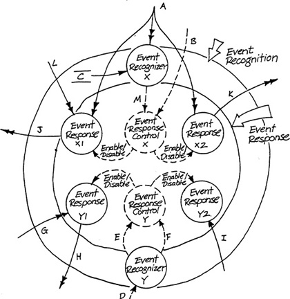
There is an important reason for separating the event recognition portion of the transformation schema from the event response portion. Although the entire essential model is implementation-independent, different portions of the model have different levels of invariance. The mechanism that recogizes the event can be changed (say by replacing the internal recognition mechanism with an external source of an event flow) without changing the definition of the event or the desired system response. The separation of the schema into two regions highlights the relatively fixed nature of the inner region, and is an application of the general heuristic of independence of parts discussed in Chapter 4 of Volume 1.
4.6 Classifying Events
Before building a transformation schema, it is useful to ask a series of questions for each event on the event list.
First, how is the event perceived by the system? For example, there may be a direct correspondence between the event occurring in the environment and the arrival of a single discrete flow. The flow may be an event flow, whose name closely matches the name of the event, or it may be a discrete data flow. As we discussed in Volume 1, Chapter 6 (The Transformation Schema), a discrete data flow implicitly has two components: the data content that makes up the flow, and an associated “trigger.” The name of the flow will describe the meaning of the data to the system, and the triggering aspect of the flow is only implied. The triggering aspect corresponds to the event in the same manner as does an event flow; that is, the arrival of the flow signals the event. We classify this type of event as flow-direct.
If the event cannot be perceived directly by the system, some event recognition mechanism will be required. Event recognizers produce an event flow that signals the event by examining continuous data flow(s) for particular values or combinations of values, or by comparing data flows to stored data. Please note that an event flow may require an event recognition mechanism. A typical example is a pulsed event flow such as the shaft encoder pulse in the Defect Inspection System (Appendix D). Every occurrence of the shaft encoder pulse does not correspond to an event; only those which signal that a sheet has reached a position of interest to the system constitute an event. This type of event in which a flow triggers an event recognition mechanism that in turn triggers a response is classified as flow-indirect
One other type of perception mechanism may be identified. In this case, the event is indirectly recognized by the passage of time. A daily report on the progress of production in a production control system is an example. We include in this class events whose occurrence can be thought of as measured from an absolute clock (the need for the daily report), and those whose occurrence is measured relatively (say a timeout), as well as scheduled events that are recognized by examining stored data to detect the arrival of a previously-stored time (such as a production schedule). These events are classified as temporal.
After identifying the perception mechanism, a second question should be asked; will the occurrence of this event prevent or permit the system to respond to another occurrence of the same or another event? If an event can affect the response to other events, there must be a control component to the system’s response – that is, there must be a control transformation that recognizes the occurrence of the event, and will activate and deactivate other sets of transformations in response. (It is useful at this point to identify the dependent events.) On the other hand, if the event in question does not affect other events, then there is no control component; the response is simply a data transformation. (This is common in commercial systems.)
The third question is, Will the occurrence of other events prevent or permit the system’s responding to this event? A positive answer to this question implies that the response is in some way managed by a control transformation; the response may be a data transformation or the production of an event flow. (It is useful at this point to identify the events on which this event depends.) If the event is independent of the previous occurrence of all other events, the response is simply a data transformation. (Again, this is common in commercial systems.)
The fourth and final question is, Which event group does this event belong to? By asking whether a given event is dependent on other events, and whether other events are dependent on it, we can think about associated events as belonging to groups. Rarely are events divided into completely independent groups. However, it is often possible to create a good preliminary partitioning by examining the dependencies identified from the previous two questions.
The classification of events described here provides us with a starting point for building a preliminary transformation model, which we will describe in the next three sections.
4.7 The Preliminary Transformation Model
A preliminary transformation model is intended to lay out the overall structure of a system. The model consists of a transformation schema with state-transition diagrams for any control transformations. (This model fulfills the conditions for schematic execution described in Chapter 9 of Volume 1 (Executing the Transformation Schema), and can thus be verified as qualitatively correct.)
The preliminary transformation schema should have a “flat” (unleveled) construction, with each transformation at approximately the same level of detail and with minimum interfaces between the transformations. For a medium-to-large system, this schema will contain a large number of transformations and will ultimately require leveling to attain a verifiable, reviewable form.
The state transition diagram (s) will describe the logic of the control transformation (s) embedded in the preliminary schema. Each diagram will represent the time-dependent interactions among a set of closely related events.
The next two sections describe the construction of the state transition diagrams and of the preliminary schema. No order is implied; it is possible to build the schema first, to build the state transition diagrams first, or to construct both components simultaneously.
4.8 Constructing State Transition Diagrams from an Event List
The overall organization of a state transition diagram can be derived directly from the interactions among the external events. The dependencies among the events are determined by answering questions two and three noted in Section 4.6 of this chapter. Event list interactions can also be explained in terms of the basic logical constructs of sequence, alternation, and repetition.
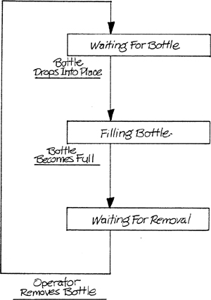
Consider the Bottle-Filling System (Appendix B). The events Bottle Drops Into Place, Bottle Becomes Full, and Operator Removes Bottle form a sequence for a particular bottling line. Under normal circumstances, the events will occur in the order given and no other event on the list will intervene. The sequence of events leads directly to a sequence of states, as illustrated in Figure 4.6. The events become the conditions that lead to the changes of state.
Figure 4.6 A sequence of States.

A single event, or a sequence of events, often is repeated a number of times within the operation of a system. The three events just mentioned for the Bottle-Filling System form a “loop” that is repeated for each bottle. This repetition is reflected in the state diagram as a transition back to a previous state in the sequence (Figure 4.7).
Figure 4.7 A Repeating Group of States.
Finally, a set of two or more events can be alternatives as successors to another event; Bottle Becomes Full can be followed by either Operator Removes Bottle or by Operator Turns Line Off. Alternatives are represented on a state diagram by multiple transitions leaving a state, as illustrated in Figure 4.8. Alternatives within an event list may also occur on a larger scale. An event and a group of events, or two groups of events, may be alternatives in the sense that they are mutually exclusive over some time period. For instance, the event Operator Sets New Bottle Size and the group Bottle Drops into Place, Bottle Becomes Full, Operator Removes Bottle are mutually exclusive. During the period of time when changing bottle size is allowed (that is, when a line is off) the three events in the group are prohibited from occurring.
Figure 4.8 Alternative Transitions.

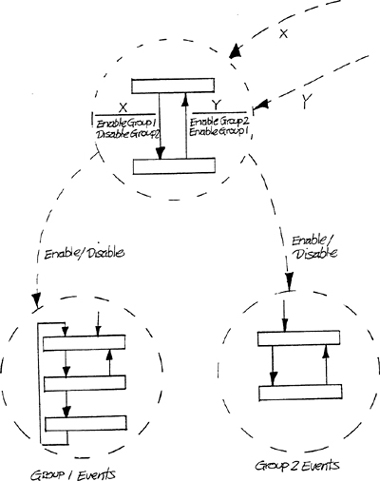
Unless a system is unusually simple, it will be necessary to create a group of state diagrams for convenient representation. One useful partitioning strategy involves mutually exclusive groups of events as discussed in the previous paragraph. In this case, a set of states is created for each group of events, and is enabled or disabled by a “higher-level” group of states dealing with the controlling events (Figure 4.9). Another convenient strategy is to identify separate groups of sensors/actors or perception/action space objects in the system’s environment, and to build a set of states for each group. For example, in the Bottle-Filling System it might be helpful to separate the states and events dealing with the pH of the product in the tank from the states and events dealing with the bottle-filling machinery.
Figure 4.9 Multiple State Transition Diagrams for Mutually Exclusive Event Groups.
If you examine the names given to the states in the preceding few figures, you will find that they represent either something in the environment that is being anticipated (for example, Waiting For Bottle) or something in the environment that is happening, possibly under system control (for example, Filling Bottle). Names such as these tie the internal behavior of the system to elements in the system’s environment and we recommend using them.
If you examine the states in the last few examples, you will also notice that they represent time intervals whose starting and stopping points are determined by externally imposed requirements. The duration of the Filling Bottle state is determined only by the bottle-filling apparatus (supply lines, valves, and so on). No change in the technology of the embedded system (for example, increasing the processor speed) can change the duration of these time intervals. The translation from event list to state transition diagram thus preserves the implementation-independence of the essential model.
One common situation encountered in translating events to a state diagram violates the pattern just mentioned. Let’s once again look at the Bottle-Filling System. The system’s response to Operator Turns Line On is conditional; the system will only turn the line on if the bottle contact is off. Thus the event Operator Turns Line On must trigger an examination of the bottle contact status, which in turn triggers one of two subsidiary event flows (Bottle Contact Is Off or Bottle Contact Is On). The destination state of the system depends on which subsidiary event flow occurs, as shown in Figure 4.10. The state between Line Off and Line On cannot be named in terms of the system’s environment. The only descriptive name would be something like Checking Bottle Contact. Furthermore, the duration of the state is inherently implementation-dependent; a faster processor will decrease the duration of the state. We will use the convention of omitting the names of such “transitory states” to emphasize their different character.
4.9 Constructing Data and Control Transformations from an Event List
The simplest connection between an event and a data transformation occurs when an event is coincident with the arrival of a discrete data flow. In this case a transformation accepts the data flow and produces whatever outputs or stored data changes are appropriate. If the system’s response depends on the occurrence of other events, the data transformation must be enabled and disabled by a control transformation. This situation is illustrated for the Bottle-Filling System by Figure 4.11.
Figure 4.10 A Transitory State.
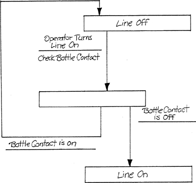
Figure 4.11 A Simple Event Response.
Another common connection between an event and a data transformation occurs when an event causes the system to begin transforming a continuous input into a continuous output. In Figure 4.12, the event flow Bottle Contact Goes On causes a control transformation to enable a data transformation accepting Weight and producing Bottle Filling Valve Control. The response may be conditional on the occurrence of other events, in which case the control transformation will produce the Enable in response to Bottle Contact Goes On only in certain states.
It is possible for an event to provoke more than one response. For example, an event flow in a process control system might enable two or more transformations of continuous inputs into continuous outputs (control loops).
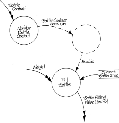
Although event flows sometimes cross the boundary from the environment to the system, it is often necessary for the system to generate the event flow internally by means of an event-recognizing transformation. The Bottle Contact Goes On event flow in Figure 4.12 results from a change of value of the continuous input flow Bottle Contact. Figure 4.13 is an expansion of Figure 4.12 to show the event recognizer. Event recognition is typically a more complex process than simply identifying a value change. Recognizing an event might involve comparing a continuous input value against stored data, comparing the values of two or more continuous inputs, counting occurrences of a discrete input (such as a motion pulse), or “timing out” from the occurrence of a discrete input.
Figure 4.12 A Continuous Transformation Enabled by an Event.

Figure 4.13 An Event Recognition Mechanism.
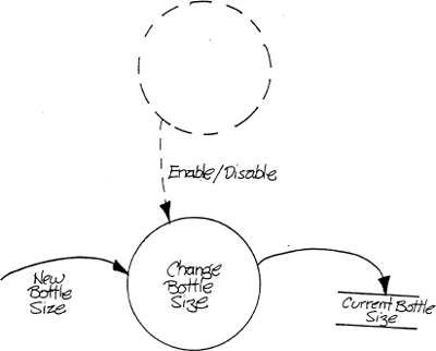
There are two types of connection possible between data transformations that respond to events; both are illustrated in Figure 4.14. Some event responses need data about the previous operation of other event responses for correct operation. Fill Bottle in Figure 4.14 needs access to the data created by the most recent operation of Change Bottle Size. In addition to the stored data connection, event responses may need to be synchronized via a control transformation. Referring once more to Figure 4.14, Fill Bottle and Change Bottle Size may not operate within the same time interval; the control transformation enables and disables the two data transformations to enforce this constraint.
Figure 4.14 Connections between Event Responses.

4.10 Constructing a Data Schema from an Event List
In Chapter 3 (Modeling External Events), we outlined a method for discovering external events using a preliminary data schema. This procedure may also be reversed – that is, a preliminary data schema may be extracted from an event list.
Chen [1] provides the basics required to turn an event list into an entity-relationship diagram. The idea is to translate sentences describing the system into entity-relationship diagram components by changing nouns into object types and verbs into relationships. (As discussed in Volume 1, Chapter 10 (Modeling Stored Data), the basic structure of natural language is the source for the structure of the entity-relationship diagram.)
Let’s take the event list for the Defect Inspection System (Appendix D) as an example. The events Operator Defines Required Product for Production Run and Operator Configures Inspection Surface might reasonably produce Figure 4.15. The verbs have become relationships and the nouns object types.
Figure 4.15 Data Schema Produced from Event List.
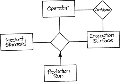
Our definition of the data schema states that only the data required by a system to support its activities should be represented within the schema. Activities may be carried out in a system’s environment that do not need to be recorded within the system’s memory. In the example just given, the system may not need to know which operator configured the inspection surface nor which operator defined the production run. If this is the case, Operator as an object type may be removed from the data schema.
4.11 Summary
The information about a system’s environment that is incorporated into an event list may be translated into a preliminary model of required system behavior. In this chapter we have introduced an orderly approach to this translation process. In the following chapter, we will discuss the completion of the preliminary model.
Chapter 4: References
1. P.P. Chen. “The Entity-Relationship Model – Toward a Unified View of Data,” ACM Transactions on Database Systems, Vol 1. No. 1 (March 1976), pp. 9-36