Appendix D – Defect Inspection System
TABLE OF CONTENTS
1. Background
2. Context Schema
3. Event List
4. Entity Relationship Diagram
5. Leveled Set of Schemas
6. Data Dictionary
7. Transformation Specifications
Problem Statement
The purpose of the defect inspection system is to chop rolls of metal foil into sheets and to sort the sheets into two bins according to a preselected product standard. Those that meet the standard go into one bin; those that do not go into another.
The system is run by a supervisor and a number of operators. The supervisor is responsible for the overall running of the system including selecting product standards, configuring each of the production surfaces, and selecting sheet sizes.
The four production surfaces are monitored by the operators; presently each operator is responsible for two surfaces. The operators can start and stop a production surface. They also wheel out full bins and replace them with empty ones.
Each production surface is equipped with a scanner, a chopper, and two air jets. Any configuration of this equipment is workable, so long as both air jets follow the chopper. The supervisor tells the system which configuration has been set up on each surface.
The scanner operates by reading the amount of light reflected from the foil. A large percentage of the reflected light for squares scanned by the scanner must be between certain values, as defined by the product standard, for the foil to be deemed “good,” otherwise the sheet must be rejected as “bad.” Irregularities in the foil will tend to produce values outside the specific range. The scanner returns data for each of the squares by organizing what it “sees” into lanes that run perpendicular to the direction of travel of the foil. Data is produced for each square in the lane, preceded by the lane numbers.
A chopper for each surface can be commanded to drop, thus cutting the roll into sheets. The chopper raises itself automatically once it has chopped the foil. The chopper must be controlled to chop the foil into sheets of constant size for a particular run. The foil may be chopped before it is scanned.
There are two air jets; one pushes the foil to the left, the other to the right. By custom, good foil is always thrown to the right.
The foil is moved along the production surface by a conveyer belt system that can be started and stopped by the operator (to start or stop the production surface is, in fact, to start or stop the conveyer system). A shaft encoder is connected to the drive roll in the belt system; each quarter revolution of the drive roll will produce a pulse from the shaft encoder. The resolution of the system is sufficient to be able to cut sheets to lengths measured in units of shaft encoder pulses.
Figure D.BKG Defect Inspection System Equipment Configuration.
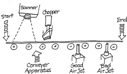
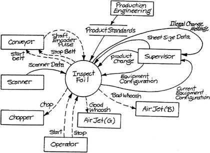
Figure D.CS Context Schema.
Event List
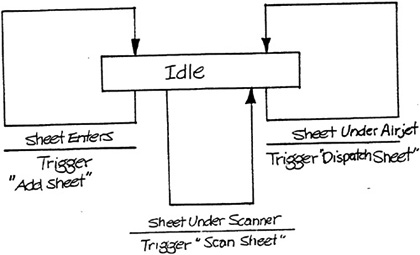
Sheet enters system.
Edge of sheet is under scanner.
Edge of sheet is under chopper.
Edge of sheet is under good airjet.
Edge of sheet is under bad airjet.
Supervisor defines product standard for production run.
Supervisor configures inspection surface.
Operator starts system.
Operator stops system.
Supervisor changes sheet size.
Figure D.ER Entity Relationship Diagram.
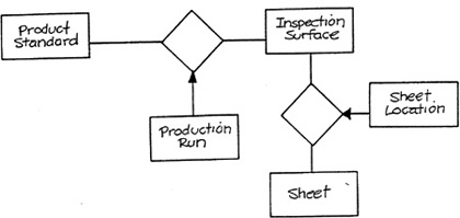
Figure D.O Inspect Foil.
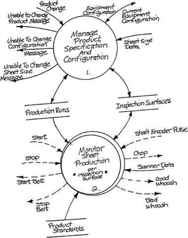
Figure D.I Manage Product Specification and Configuration.
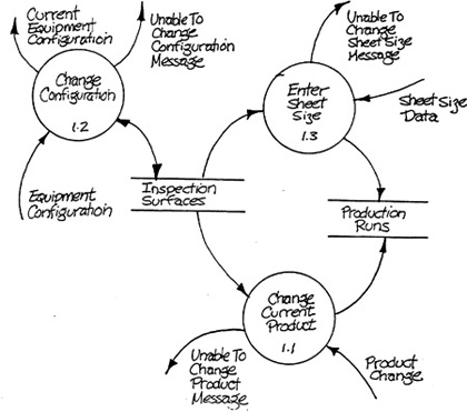
Figure D.2 Monitor Sheet Production.
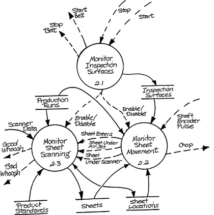
Figure D.2.1 Monitor Inspection Surface.

Figure D.2.1.1 Control Inspection Surfaces.
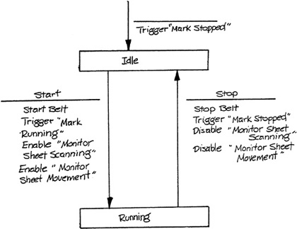
Figure D.2.2 Monitor Sheet Movement.

Figure D.2.2.1 Control Sheet Movement.

Figure D.2.3 Monitor Sheet Scanning.
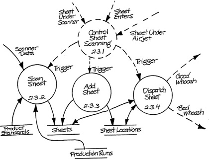
Figure D.2.3.1 Control Sheet Scanning.
Data Dictionary
Transformation Specifications
1.1 Change Current Product
Precondition 1
PRODUCT CHANGE occurs
and STATUS of referenced INSPECTION SURFACE is “off;”
Postcondition 1
the PRODUCTION RUN referencing the INSPECTION SURFACE indicated by PRODUCT CHANGE contains a reference to the provided PRODUCT STANDARD
Precondition 2
PRODUCT CHANGE occurs
and STATUS of referenced INSPECTION SURFACE is “on”
Postcondition 2
UNABLE TO CHANGE PRODUCT MESSAGE is produced
Precondition 1
EQUIPMENT CONFIGURATION occurs
and STATUS of referenced INSPECTION SURFACE is “off”
and both SCANNER LOCATION and CHOPPER LOCATION are less than both GOOD AIR JET LOCATION and BAD AIR JET LOCATIONS
Postcondition 1
the referenced INSPECTION SURFACE contains the data from EQUIPMENT CONFIGURATION
and CURRENT EQUIPMENT CONFIGURATION corresponds to EQUIPMENT CONFIGURATION
Precondition 2
EQUIPMENT CONFIGURATION occurs
and STATUS of referenced INSPECTION SURFACE is “off”
and some part of Precondition 1 does not hold
Postcondition 2
CURRENT EQUIPMENT CONFIGURATION corresponds to referenced INSPECTION SURFACE
and UNABLE TO CHANGE CONFIGURATION MESSAGE occurs
Precondition 3
EQUIPMENT CONFIGURATION occurs
and STATUS of referenced INSPECTION SURFACE is “on”
Postcondition 3
UNABLE TO CHANGE CONFIGURATION MESSAGE occurs
Precondition 1
SHEET SIZE DATA occurs
and STATUS of referenced INSPECTION SURFACE is “off”
Postcondition 1
referenced PRODUCTION RUN contains the SHEET SIZE from SHEET SIZE DATA
Precondition 2
SHEET SIZE DATA occurs
and STATUS or referenced INSPECTION SURFACE is “on”
Postcondition 2
UNABLE TO CHANGE SHEET SIZE MESSAGE occurs
Precondition 1
none
Postcondition 1
STATUS of INSPECTION SURFACE is “on”
2.1.3 Mark Stopped
Precondition 1
none
Postcondition 1
STATUS of INSPECTION SURFACE is “off”
2.2.2 Update Sheet Locations
Precondition 1
none
Postcondition 1
the LOCATION for every SHEET-LOCATION referencing the INSPECTION SURFACE is greater by 1
Precondition 1
There is a SHEET whose LOCATION is one SHEET SIZE from the start of the INSPECTION SURFACE
Postcondition 1
SHEET ENTERS is produced
Precondition 2
There is a SHEET whose LOCATION is equal to the SCANNER LOCATION
Postcondition 2
SHEET UNDER SCANNER is produced
Precondition 3
There is a SHEET whose LOCATION is equal to GOOD AIRJET LOCATION
Postcondition 3
SHEET UNDER GOOD AIRJET is produced
Precondition 4
There is a SHEET whose LOCATION is equal to BAD AIRJET LOCATION
Postcondition 4
SHEET UNDER BAD AIRJET is produced
Precondition 5
There is a SHEET whose LOCATION is equal to CHOPPER LOCATION
Postcondition 5
CHOP is produced
Local term: USEFUL DATA is the SECTOR VALUES for each LANE with LANE NUMBER between 1 and SHEET SIZE for the PRODUCTION RUN referenced by the INSPECTION SURFACE
Precondition 1
SCANNER DATA occurs for an INSPECTION SURFACE
and 95% of the SECTOR VALUES of USEFUL DATA are between HIGH LIMIT and LOW LIMIT of the PRODUCT STANDARD referenced by the PRODUCTION RUN for the INSPECTION SURFACE
Postcondition 1
DEFECT STATUS is “good” for the SHEET whose SHEET LOCATION matches the SCANNER LOCATION for the INSPECTION SURFACE
Precondition 2
SCANNER DATA occurs for an INSPECTION SURFACE
and Precondition 1 does not hold
Postcondition 2
DEFECT STATUS is “bad” for the SHEET whose SHEET LOCATION matches the SCANNER LOCATION for the INSPECTION SURFACE
2.3.3 Add Sheet
Precondition 1
none
Postcondition 1
There is a SHEET whose ID is 1 greater than the previously highest SHEET ID and whose DEFECT STATUS is “unknown”
and There is a SHEET LOCATION referencing the new SHEET and the INSPECTION SURFACE whose LOCATION is O
Local term: MATCHING GOOD SHEET is a SHEET whose SHEET LOCATION matches GOOD AIRJET LOCATION and whose DEFECT STATUS is “good”
Local term: MATCHING BAD SHEET is a SHEET whose SHEET LOCATION matches BAD AIRJET LOCATION and whose DEFECT STATUS is “bad”
Precondition 1
MATCHING GOOD SHEET exists
Postcondition 1
GOOD WHOOSH is produced
and the SHEET and SHEET LOCATION referenced by MATCHING GOOD SHEET do not exist
Precondition 2
MATCHING BAD SHEET exists
Postcondition 2
BAD WHOOSH is produced
and the SHEET and SHEET LOCATION referenced by MATCHING BAD SHEET do not exist