
Chapter 3. Aspects of Architecture
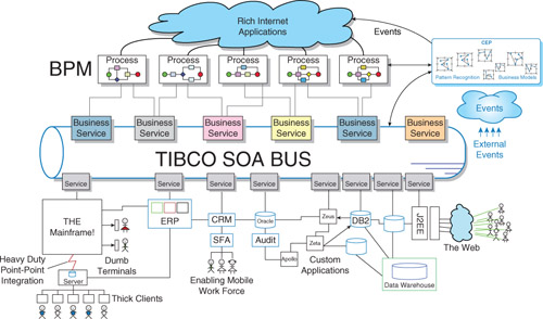
To many people the term architecture evokes images of box-and-line diagrams such as the one shown in Figure 3-1. This type of perspective is important as it shows the components and their communications channels, but it only tells part of the story. It does not, for example, tell you the nature of the work being performed nor does it tell you how the participants collaborate to perform that work.
Figure 3-1. Sketch of an Architecture Pattern
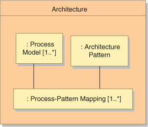
The organization of the work and the collaboration of the participants in performing that work are also essential aspects of the architecture (Figure 3-2). In the IT world the work takes the form of processes. The picture is completed by mapping these processes onto the elements of the architecture pattern. In all but the most trivial of circumstances the architecture will involve more than one process, each of which is mapped onto the architecture pattern.
Figure 3-2. Essential Aspects of an IT Architecture
Process Models
Process models are just structures of activities that indicate both the activities being performed and the artifacts that are exchanged. In many cases these artifacts are simply data structures, but there may be physical artifacts as well such as goods and payments.
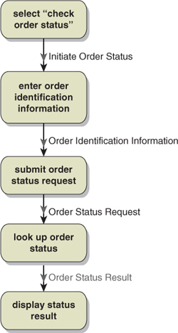
In the process model example shown in Figure 3-3 we see five activities. The first activity simply selects the work to follow, in this case the checking of the order status. The interaction with the second activity involves a communication indicating that “check order status” has been selected. The second activity gathers the information needed to identify the order so that its status can be retrieved and communicates this information to the next activity. The third activity submits the request for the order status and communicates this request. The fourth activity executes the order status request and returns the order status result. The final activity displays the status result.
Figure 3-3. Check Order Status Process Model
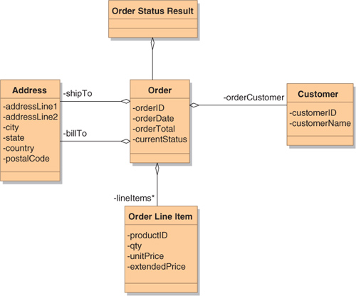
In most of the interactions in this process, the nature of the information being conveyed is relatively simple and the information content is implicit in the label given to the communications artifact in the diagram. But the term “order status result” is ambiguous: How much information does it actually convey? Such ambiguity makes it necessary to model the information content of the communication as an adjunct to the process model. Figure 3-4 shows some of the information that might be included in the result of this example. Note that the actual data structures are not being modeled—only their information content.
Figure 3-4. Possible Information Content of an Order Status Result
Architecture Patterns
The architecture pattern shows the structure of the participants in the process. It identifies the participants and the communication channels available between them. It also describes any constraints on the participants and communications channels.
Figure 3-5 is an example pattern found in many enterprises today. The customer (a person) interacts locally with a browser using keyboard and display. The browser interacts with Apache Tomcat application servers using HTTP over a WAN. The application server accesses services via SOAP over JMS, and these services are provided by TIBCO ActiveMatrix BusinessWorks™ implementations. The services access the back-end Order Management System via proprietary interfaces. In keeping with the total architecture concept, both people and systems are included in the architecture pattern.
Figure 3-5. Architecture Pattern Example
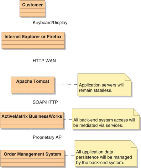
As part of the architecture pattern it is appropriate to indicate constraints on the roles that the participants can play. The example shows three such constraints: Application servers will remain stateless; access to back-end systems will be mediated via services; and application data persistence will be managed by the back-end systems.
Process-Pattern Mapping
Mapping the process model onto the architecture pattern involves making design decisions about which participants will perform which activities in the process. The example of Figure 3-6 uses a UML Activity Diagram to show the mapping. Each of the diagram’s swimlanes represents one of the process participants. The process activities are then overlaid on the swimlanes, thus indicating which of the participants is responsible for which of the activities. Interactions between activities assigned to different participants indicate the need for those participants to interact and thus indicate the need for interfaces.
Figure 3-6. Check Order Status Process-Pattern Mapping
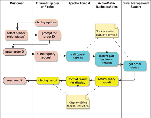
One of the interesting things that occurs in mapping the process activities onto the participants is that some process activities become distributed across multiple participants. In this example, the “lookup order status” activity becomes three activities distributed across Apache Tomcat, ActiveMatrix BusinessWorks™, and the Order Management System. Similarly the “display status results” becomes three activities distributed across ActiveMatrix BusinessWorks, Apache Tomcat, and the browser.
Why Should You Care about Architecture?
It is appropriate to ask why you should care about architecture. The reality is that real-world processes and patterns are complex, and there are many ways in which the process models can be mapped onto the architecture patterns. These mappings reflect design decisions: Which participants should be responsible for each activity? Which activities should be distributed across multiple participants and how? Which communications channels should be used for each interaction?
Even with the best architecture pattern, an inappropriate mapping can lead to a show-stopping failure—one that will require major rework. The goal of mapping the process onto the pattern is to make the mapping explicit so that it can be examined, reviewed, and refined while it is still a paper design. Changes at this stage are inexpensive and easily accommodated.
This mapping has to be done anyway at some point to complete the design, and you also need to do the mapping to evaluate the adequacy of the architecture pattern. The only real question is when to do the mapping. As we shall see in Chapter 5, evidence from real projects shows that doing the mapping early in the project can reduce overall project duration by as much as 25%. The larger and more complex the project, the bigger the impact that architecture has upon project duration.
It is important to record the mapping: Draw the picture and save it. All too often the mapping is done verbally: The architecture pattern is displayed and someone talks through how the process is executed by the participants in the pattern. Unfortunately, the only people who will understand the mapping are those who participated in the discussion, and likely that understanding will be incomplete. What you lose with this approach is the ability to share the mapping with others. Architects who did not participate in the discussion will be unable to learn, review, and comment. Businesspeople will not be able to review and validate the proposed process execution. Designers and developers will not fully understand how their components are expected to participate in the process.
An ATM Architecture Example
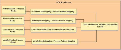
Since the query example was relatively simple, let’s take a look at a richer architecture, this time of a banking system involving an automated teller machine (ATM). This architecture (Figure 3-7) involves four different process models (withdraw cash, make deposit, check balance, and transfer funds) all mapped onto the same architecture pattern.
ATM Architecture Pattern
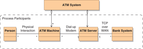
The architecture pattern for this example (Figure 3-8) is relatively simple. The ATM System comprises two types of components: ATM Machines and an ATM Server. The remaining components are the people (customers) who use the ATM service and the Bank Systems that actually manage the account balances.
Figure 3-8. ATM Architecture Pattern
ATM Withdraw Cash Process Model
There are four processes executed in this architecture. One of these is the withdraw cash process illustrated in Figure 3-9. The figure shows the sunny-day scenario for this process. This particular depiction of the process is not necessarily specific to the ATM approach and describes equally well an interaction with a human teller, albeit with some differences in the artifacts involved.
Figure 3-9. Withdraw Cash Process Model
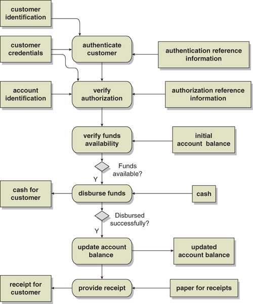
The withdraw cash process begins with the customer presenting credentials (e.g., the ATM card) and some form of identification (e.g., the PIN number). The first activity authenticates the customer using some reference information that indicates the acceptable associations between credentials and identification. Next, the account is identified and the authorization of the customer to access the account is established. The availability of funds is established and, if available, the funds are disbursed to the customer. The process concludes with the account balance being updated and a receipt being given to the customer.
Beyond the structuring of the activities, the process indicates the inputs required for each activity and the results that are produced. The inputs and results are important because they generally indicate the need for interactions with other business processes and their supporting systems. Interactions often require effort to implement, and thus recognizing the need for such interactions clarifies the true scope of the project.
This process model is, of course, incomplete, for it does not show what happens if the funds turn out to be unavailable or if the funds are not disbursed successfully. In a real architecture, these and other alternate scenarios would have to be detailed from a business process perspective.
The sequencing of activities in the process model should be carefully considered. If the process model shows a specific sequence of activities, as in Figure 3-9, someone implementing that process would have no choice other than to execute those activities in that specific sequence.
To allow maximum flexibility in implementing processes it is important to indicate where activities can be done in parallel. Figure 3-10 shows a hypothetical restructuring of the withdraw cash process to show allowed parallelism. This process indicates that the activities of authentication, authorization, and verifying funds availability could be performed in parallel. Similarly, it indicates that the printing of the receipt and the updating of the account balance could be done concurrently.
Figure 3-10. Withdraw Cash Process Model with Parallelization
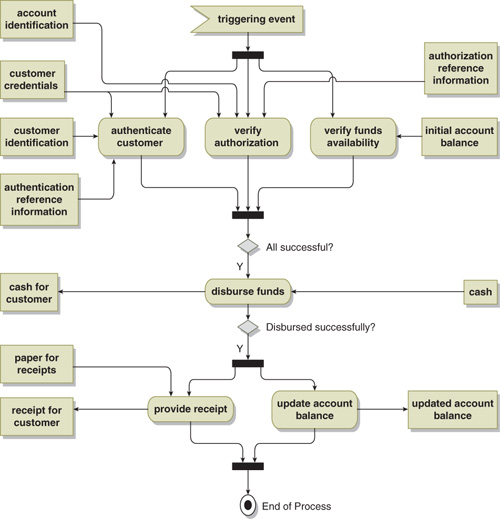
Showing activities in parallel provides the maximum flexibility when implementing the process. The designer is now aware that certain activities could be performed simultaneously to minimize latency in the process. On the other hand, a sequential execution of the activities shown earlier is also perfectly acceptable.
ATM Withdraw Cash Process-Pattern Mapping
The mapping of the withdraw cash process onto the ATM architecture pattern is shown in Figure 3-11. As in the earlier example, some of the activities become distributed across multiple participants. In this particular case, the distribution itself introduces some exception scenarios that require some refinement of the process. One particular scenario of concern is when there might be a delay between the verification of funds availability and the reporting of the funds distribution. The problem to be avoided here is one of the funds still appearing to be available in the bank system and being withdrawn (via some unspecified mechanism) before the account balance can be updated.
Figure 3-11. Withdraw Cash Process-Pattern Mapping
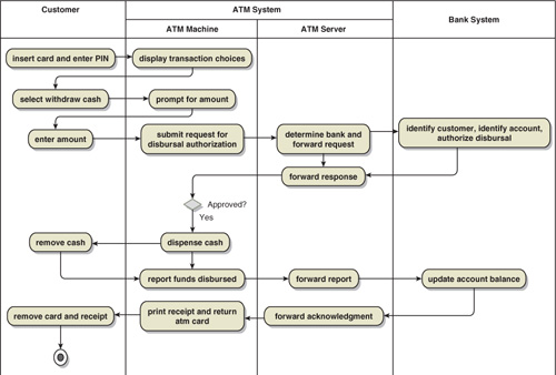
The solution to this problem is a refinement of the “verify funds availability” activity into one that obtains a disbursal authorization. This disbursal authorization places a hold on the funds in the account and authorizes the funds to be delivered to the customer within some specified time period. This dialog involves the return of an authorization number with the authorization and the requirement to supply this same authorization number when the funds disbursal is reported. At that time the hold on the funds is removed and the account is debited by the amount actually delivered.
The example in Figure 3-11 illustrates the kind of design problem that can arise as the process is mapped onto the architecture pattern. Explicitly modeling the mapping affords the opportunity to not only identify the design problem but also modify the design to address the issue.
ATM Architecture Example with Services
Designs involving services can be readily represented in the same manner. The starting point is updating the architecture pattern to indicate where services come into play (Figure 3-12). In this example the Account Management Service has been added with the ATM Server providing the service implementation and the ATM Machine using the services.
Figure 3-12. ATM Architecture Pattern with Services
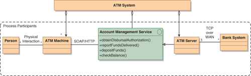
Simply adding the service to the architecture pattern does not indicate how the service operations participate in the process. That information is added as the process is mapped onto the architecture pattern. Figure 3-13 shows the process-pattern mapping modified to indicate which service operations are being invoked.
Figure 3-13. ATM Withdraw Cash Process-Pattern Mapping with Services
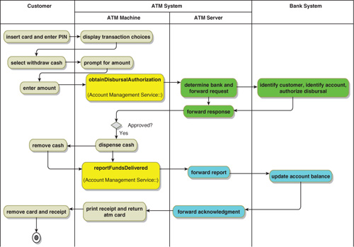
Augmenting the mapping to show where process operations occur provides a lot of useful information. It shows both what happens behind the scenes when the operation is invoked and how the operation supports the larger business process. Both perspectives are essential to validate that the service operations can adequately support their intended utilization. Furthermore, if there are expectations of reuse for service operations, the mappings of other business processes should be able to use the same operations. For example, a funds transfer can be assembled from an obtainDisbursalAuthorization and reportFundsDelivered on one account along with a depositFunds on a second account.
Summary
There are three essential aspects to an architecture: the architecture pattern, one or more process models, and the mappings of those process models onto the architecture pattern. The architecture pattern shows the participants in the process, the communications channels between them, and the constraints on their usage. Each process model shows how a particular kind of work is organized and the artifacts (information and physical entities) involved in performing that work. The process-pattern mapping shows how the participants in the process carry out the work of the process.
The mapping of the process activities onto the process participants provides many advantages:
• It surfaces many design decisions and makes their resolution explicit. When individual activities are performed by a single participant, the mapping indicates the participant.
• When one activity provides inputs to another and these activities are assigned to different participants, the mapping indicates the need for the two participants to interact—and the need for an interface!
• When an activity becomes split across several participants, the mapping indicates the detailed responsibilities of each participant along with the need for interactions between them.
• Analyzing the mapping allows you to identify bottlenecks and determine where load distribution will be required.
• The mapping enables a detailed examination of failure modes (the loss of individual participants and individual interactions), which may motivate a modification to the process to better handle the failures.
Documenting the full architecture, including the process-pattern mapping, is important. It makes the architecture explicit so that it can be readily examined and critiqued by other architects. It affords an opportunity for stakeholders (businesspeople, in particular) to validate the process definitions and verify that the proposed implementation is suitable for their needs. Finally, it helps the designers responsible for the individual participants clearly understand their design requirements, including the role that their components play in the larger design.
Architecture documentation clarifies the roles that services are expected to play in a design. It shows how service operations participate in business processes, which are the ultimate source of their requirements. It shows the internal architecture of the services, a perspective that is essential in verifying the service operation’s ability to support the business process. And finally, it affords the opportunity to establish the potential for reuse: the participation of the same service operation in two or more processes.