
7
Enforcing Security
As the world grows more reliant on electronics, and especially with the addition of connectivity to IoT applications, security has become a vital concern. If a connected device stores any type of sensitive data – such as Wi-Fi passwords, certificates, or personal information – this data needs to be secured. There is a common sentiment that if a device is connected to the internet and has some value, someone will try and hack it.
Even if your hardware implements specific technology features for security such as TrustZone, if your software has security-related flaws, it can compromise your entire device. For modern developers, software must be architected with security as a primary driving requirement and not an afterthought. This chapter contains several examples of secure software implementation, but to truly build security into your device, it must be planned for from the start of a project.
To provide some guidance on how to holistically implement security into Cortex-M devices, in hardware and software, Arm introduced the Platform Security Architecture (PSA) framework. We will start by going over the four stages of PSA and then move on to running secure software examples.
In a nutshell, the following topics will be covered in this chapter:
- Breaking down PSA
- Example 1 – Secure versus non-secure hello world
- Example 2 – TF-M
Breaking down PSA
The PSA framework was introduced by Arm in 2017. It was created to reconcile the growing number of intelligent connected devices around the world with the fractured and varied approach to securing them. Cortex-M-based products are as numerous as they are different; any one device has hundreds of unique hardware or software products from dozens of companies inside it. If even one of these products has a security gap, the entire device has a security vulnerability. By 2017, the need was clear for an industry-wide framework to holistically address the security problem in a cost-effective manner. The PSA framework fills that need.
We briefly covered PSA in Chapter 2, Selecting the Right Software. There is a white paper available at https://www.psacertified.org/blog/program-overview-digital-whitepaper/ with an in-depth explanation of the three parts of PSA, as listed here:
- Threat models and security analyses, derived from a range of typical IoT use cases
- Architecture specifications for firmware and hardware
- Open source reference implementation of the firmware architecture specifications
The threat models and security analyses are available at https://www.psacertified.org/development-resources/building-in-security/threat-models/, and we will also dive deeper into the PSA’s 10 security goals in the upcoming section. The architecture specifications for firmware and hardware are available for free at https://www.psacertified.org/development-resources/building-in-security/specifications-implementations/.
The open source reference implementation of the firmware architecture specifications is the Trusted Firmware-M (TF-M) software stack, discussed at the end of this chapter with example implementations. In addition to the three parts of the PSA framework described previously, there is a formal program intended to verify that devices follow the PSA framework in practice: PSA Certified. This program defines three levels that chips, boards, and software stacks can be tested against to verify their robustness against security threats.
All these resources can be put together, enabling Cortex-M developers to select security-hardened hardware, develop resilient software, and certify that their product is built with the right level of security prioritized. While there is a lot of material to sort through, it may be helpful to think about each resource as contributing to one of these four stages of security design:
- Analyze: Understand the assets you are protecting and the potential security threats you face
- Architect: Create your design stemming from the identified security requirements
- Implement: Develop your product from secure hardware, firmware, and software stacks
- Certify: Obtain a PSA Certification through an independent third party
Analyze – threat modeling and the 10 security goals
The first step is to understand what use case your device is intended for and how it will be deployed through its life cycle. An IoT asset tracker is different from a smart door camera, for example.
Then, with your device’s life cycle laid out, you need to understand the security threats that will exist in your device. Distinctions between use cases, such as being connected to the internet or physically accessible to the public, will affect the type of threats your device will face.
PSA provides a list of possible attack vectors and threat models to frame your analysis, which is fully accessible at https://www.psacertified.org/app/uploads/2020/10/PSA_Certified_Threat_Model_and_Security_Goals_RC3.pdf.
Here is a brief summary of the possible threats, organized into two categories:
- Software attacks
- Spoofing the system identity, faking trustworthiness
- System cloning to steal the device or app identity
- Spoofing the firmware update sender’s identity, injecting firmware
- Image tampering, gaining system access
- Update rollbacks for legacy bug exploitation
- Software data tampering polluting trusted services
- Persistent malware exploiting vulnerabilities across reset cycles
- Deniability and erasing logs and history through various methods
- Side-channel attacks extracting sensitive data
- Software data extraction fooling communication interfaces
- Abusing communication between trusted and non-trusted services
- Unrestricted access through breached trusted services
- Hardware attacks:
The list of possible attack vectors is always evolving and changing, but this list offers a good place to start when considering possible security vulnerabilities.
The final step in the analysis is to create security requirements based on these possible attack vectors. To guide you in this process, the Platform Security Model contains 10 security goals in the PSA framework. These goals are intended to provide an implementation-agnostic way to think about the essential features of a secured, trusted product. The 10 security goals provide a high-level common language to discuss security robustness rules, with specific implementations coming later in the process.
The full Platform Security Model document is very detailed and can be found at the same link provided for threat modeling on the PSA Certified website. Here we will briefly introduce each of the 10 security goals with a straightforward explanation:
- Goal 1: Devices are uniquely identifiable
In order to be properly trusted, a device must be provably unique. For example, when connecting your phone to your new Bluetooth headphones, those headphones must be uniquely identifiable to ensure your phone connects to the intended target. If they are not unique, it becomes a security risk: you could accidentally connect to a malicious device posing as your headphones, or a man-in-the-middle attack could take place by intercepting communications before forwarding them along.
- Goal 2: Devices support a security life cycle
Every product goes through many environments in its life, from creation to death. At each point in this life span, devices should be as secure as necessary to avoid threats. This includes taking proper precautions during development, ensuring a trustworthy manufacturing and deployment process, protecting the device virtually and physically when in use, and seeing it through a proper end-of-life. Different devices will need more attention at different stages. A connected power station management system should be physically protected from malicious actors, and, for example, a mass-produced smart lightbulb should have special protection against virus injection during the manufacturing stage.
- Goal 3: Devices are securely attestable
The definition of attestable is as follows: to affirm to be correct, true, or genuine. This combines with the first two goals to assert that a device must be provably trustworthy at every point in its life cycle.
- Goal 4: Devices ensure that only authorized software can be executed
This is a straightforward goal. In some cases, such as allowing user-inputted code, unauthorized software may have to be run on the device. In these cases, it should be ensured that this unauthorized software cannot compromise device security. Secure boot and secure loading processes are fundamental pillars in assuring this goal is met.
- Goal 5: Devices support secure updates
For connected devices that are continually updated, ensuring security and authenticity during an update is essential. Multiple components of the device should be updatable, including security credentials, programmable hardware configurations, and software.
- Goal 6: Devices prevent unauthorized rollbacks of updates
As devices are updated to fix security vulnerabilities, they should not be allowed to revert to a previous (and vulnerable) software version. This anti-rollback principle applies to both accidental and malicious attempts. Recovery of data is the only exception to this rule and should be handled with care.
- Goal 7: Devices support isolation
Isolation contributes to hardening security by reducing attack surface areas. Even if an attacker breaks into one portion of the device (in hardware or software), the other portions are not accessible. These isolation boundaries apply between device software sections and the device software and the outside world.
- Goal 8: Devices support interaction over isolation boundaries
Perhaps a clear requirement stemming from the previous goal is the need to interact over isolation boundaries to create a functional system. This interaction should not be able to compromise any individual section, however, and exchanged data must be validated as confidential and trustworthy.
- Goal 9: Devices support the unique binding of sensitive data to a device
Sensitive data, such as secret keys or credentials, deserves to be treated with extra care. This goal mandates binding sensitive information to an individual device to prevent secret data from spreading elsewhere. It is also recommended to store sensitive data in inherently secure storage, enable access to select individual device users, and prevent data access in certain security states, such as during debugging.
- Goal 10: Devices support a minimal set of trusted services and cryptographic operations that are necessary for the device to support the other goals
To minimize attack surfaces and enable security analysis, trusted software or services should be kept as small as possible. Only implement the security features required and implement them excellently.
You can use these security goals to address the identified attack vectors for your device and detail the list of specific security requirements for your project. At this point, you are ready to start architecting a solution to these security requirements.
Architect – References, suggestions, and APIs
In this step, you translate security requirements into an appropriate system in both hardware and software. The PSA framework does offer some documentation and examples to guide in this process, but naturally, some architecture decisions will have to be made regarding your specific project.
The guidance PSA provides in this architecture creation phase is broken into two areas: selecting existing hardware or software to use in your project and creating your own.
Selecting the right SoC, device, and software
There are detailed recommendations for creating a secure system-on-chip (SoC) for device makers to follow in the Trusted Base System Architecture document. It is too low-level to be useful in this context and all that you need to know is which SoCs have followed this security analysis process. This is where the concept of being PSA Certified comes in, which is covered as the last phase for your device to go through in this section. Just as end products can be certified as having factored in security decisions, so too can SoCs.
A guide to selecting the right SoC for your design can be found at https://www.psacertified.org/blog/choosing-iot-security-chip/. A key offering from Arm is the TrustZone technology, mentioned in Chapter 1, Selecting the Right Hardware, which creates physical isolation between critical firmware and the rest of the application. You will find SoCs that implement different levels of security best practices on top of Arm TrustZone technology in the Cortex-M space from that list.
Similarly, there is a list of software that has been independently certified to be fit for security applications. They can be found at https://www.psacertified.org/certified-products/?_standard=psa-certified-system-software. Lastly, if you are only looking to develop software on top of an existing hardware device, there is a list of certified devices available at https://www.psacertified.org/certified-products/?_standard=psa-certified-oem as well.
Creating secure hardware and software
The PSA Certified site contains varied resources for architecting security-focused systems. The full list of resources can be found at https://www.psacertified.org/development-resources/building-in-security/specifications-implementations/. It includes Arm-specific, low-level suggestions around hardware, firmware, and Root of Trust (RoT) requirements. Another resource is a list of functional APIs, easing the implementation of cryptography, secure storage management, and attestation functions.
Implement – Creating a secure system
This phase is about creating your device based on the proposed architecture that meets your identified attack vectors. Most of this book is focused on helping you implement software on Cortex-M devices, with examples being crucial for aiding and speeding up development. Similarly, the PSA offers an example implementation of PSA specifications on Cortex-M devices. TF-M is this reference and is open source for all to refer to and build from. We will dive into some TF-M examples later in this chapter.
Certify – PSA certification levels
The last step after creating a device with security in mind is to certify that your device meets the security requirements. This certification helps developers and customers trust and rely on this component to achieve the level of security they need. This is helpful for devices that will be used as a foundation to build other solutions from to prove that security was a key design consideration. We referenced the list of SoCs, devices, and software that are already certified in the Architect – References, suggestions, and APIs section (which can be found here: https://www.psacertified.org/certified-products/).
The certification process evaluates SoCs, devices, and software to be tested under laboratory conditions that measure their level of security. There are three progressive levels of this security certification:
- Level 1: Security principles
For a device manufacturer, this is simply achieved by selecting pre-certified silicon and a pre-certified software platform for your device and then implementing the 10 aforementioned security goals. It requires the completion of a critical security questionnaire (based on the 10 security goals and identified threat models). Level 1 is also the limit for certification for devices, system software, and APIs. The latter levels are intended for SoCs building higher levels of security into the heart of devices.
Important note
Common software such as FreeRTOS from AWS and common SoC families such as ST STM32s and NXP i.MXs are all certified under Level 1.
- Level 2: Software attacks
PSA Certified Level 2 is specifically for SoCs and provides evidence of protection against scalable software attacks. Chips are evaluated for 25 days at an independent laboratory, undergoing penetration testing and vulnerability analysis focusing on the PSA Root of Trust (PSA-RoT). Chips must prove they can withstand the threats presented in the PSA-RoT Protection Profile, available here for those curious: https://www.psacertified.org/getting-certified/silicon-vendor/overview/level-2/. Chips at this level are best suited to protecting key assets that are available over software but do not offer physical access to attackers, such as various smart home devices inside the home.
- Level 3: Hardware attacks
PSA Certified Level 3 is also specifically for SoCs and provides evidence of protection against more sophisticated attack types, including side channel and physical attacks. Chips are evaluated for 35 days and undergo rigorous security testing from software and physical attack vectors. It is best to select chips with this level of security for your device if protecting high-value assets that are publicly accessible, such as a smart home door lock. Information is available here: https://www.psacertified.org/getting-certified/silicon-vendor/overview/level-3/.
Important note
There is also a separate certification available for functional APIs that do not have independent levels. This is what the Keil RTX5 RTOS is certified under.
There is an extensive list of resources to obtain certification at any of these levels and those interested can view it on the PSA Certified website: https://www.psacertified.org/development-resources/certification-resources/. If you are interested in getting your Cortex-M device PSA Level 1 Certified, follow the steps previously outlined and submit your certification request through the PSA Certified website. More commonly, this understanding of PSA Certification is helpful to narrow down SoC purchasing decisions to those meeting your desired security requirements. This goes for selecting secure base firmware as well.
With this helpful PSA security framework in mind, we can narrow our focus back down to the implementation of secure software. In the remainder of this chapter, we will discuss how to start from security examples, learn how the software implements key security concepts in practice, and how to leverage the open source TF-M code through some example implementations on the Cortex-M33 and Cortex-M55.
Example 1 – Secure versus non-secure hello world
In general, when you start a new project for an Arm Cortex-M device with TrustZone (such as the Cortex-M33 and Cortex-M55), the project will comprise two sub-projects: a secure and non-secure project. Secure and non-secure code have their own boot code and are compiled and linked independently in the sub-projects. Both secure and non-secure code run on the same processor but are loaded in isolated and independent areas of memory. All the code that handles security and configuration, such as boot code, firmware updates, and crypto libraries, is placed in the secure project. The rest of the application code is placed in the non-secure project. The objective is to minimize the amount of code in the secure project and run exhaustive checks on it for security vulnerabilities.
Important note
The implementation of secure software with TrustZone inherently follows the 10 security goals – specifically, Goal 7 of isolating secure and non-secure areas; Goal 8 of enabling interaction between these areas; and Goal 10 of minimizing the number of secure services on a device. Thinking about implementing security in the framework of PSA’s 10 security goals can help organize your thinking to better understand ostensibly complex security implementation.
The secure versus non-secure code is managed and defined by the memory map settings. All physical memory addresses are assigned as either secure or non-secure. The assignment is managed by the Security Attribution Unit (SAU), which is only accessible in the secure state. This provides independent memory protection for each security state. When an area of memory is addressed in software, the load and store instructions acquire the secure or non-secure attribute. Thus, non-secure access to a secure address will result automatically in a memory fault. A non-secure program can only call a secure function and return to the non-secure mode in a standardized way, explained in this upcoming example.
Here is a quick list of what the secure sub-project and non-secure sub-projects can and cannot do for reference:
- The secure sub-project can access everything
- The non-secure sub-project cannot access secure sub-project resources
- Both secure and non-secure code is running on the same processor and can implement independent scheduling
Now, with several security principles discussed, we will go through an example of them in context. This example walks through the secure version of hello world on the Cortex-M33-based NXP board, showing in detail how the processor switches from a secure to a non-secure state and how to call a secure function from a non-secure state.
To replicate the example in this section, you will be using the following:
|
Platform |
NXP LPCXpresso55S69 |
|
Software |
hello world (secure and non-secure) |
|
Environment |
Local PC |
|
Host OS |
Windows |
|
Compiler |
Arm Compiler for Embedded |
|
IDE |
Keil MDK |
Obtaining and building the application
To start, open the Keil MDK IDE and get the examples through the Pack Installer widget. Select the LPC55S69 device and copy hello_world_ns and hello_world_s into your workspace. If the Copy action is disabled, close all the projects open in your Keil MDK IDE and try again. In the window that pops up, check the Use Pack Folder Structure checkbox and uncheck the Launch µVision checkbox:
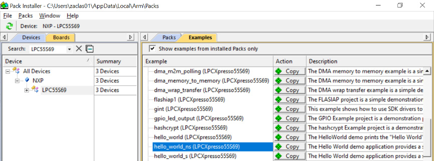
Figure 7.1 – The Pack Installer window with NXP LPC55S69 board examples
Once copied, in the IDE, select Project | Open Project… and navigate to the copied hello_world_s example. Under this example, you will find a µVision Multi-Project file called hello_world.uvmpw. If you copied the example to your Documents folder, you will find this file under this path:

Figure 7.2 – File navigation to the hello world Trustzone example
Upon opening this µVision Multi-Project File, both the sub-projects will be loaded in the same view. Keil MDK tools provide something called a multi-project workspace view for compiling and running TrustZone-based applications that have both a secure and non-secure sub-project associated with it. Other IDEs such as MCUXpresso also provide a similar feature to make the development of these applications easier. This way, you can control and view the source files for both applications that are going to run on the same target without switching between project spaces. The following figure shows what this looks like on your screen:

Figure 7.3 – A multi-project workspace view of the hello world example
By default, this project is configured to use the Arm Compiler for Embedded toolchain to compile the application. Arm provides a feature called Cortex-M Security Extension (CMSE) in the compiler for the development of secure code on Cortex-M processors. It is documented in detail at https://developer.arm.com/documentation/100720/0200/CMSE-support. CMSE features are available in other compiler toolchains such as GCC as well. An important C pre-processor macro, __ARM_FEATURE_CMSE, is one of the features that indicates whether code is running in secure or non-secure mode. The access to secure and non-secure aliases for all peripherals is managed using this compiler macro.
There are two function attributes to support calls between secure and non-secure modes:
- __attribute__((cmse_nonsecure_entry)): A secure function that can be called by non-secure code
- __attribute__((cmse_nonsecure_call)): A call to a non-secure function from secure code
To enable the CMSE support attributes and the usage of the pre-processor macros, you will need to compile your software project by passing the following options to the Arm Compiler for Embedded:
-mcpu=cortex-m33 -mcmse
This is set in the Keil µVision example by selecting the Secure Mode software model on the Target tab. To check these settings, first, right-click on the hello_world_s sub-project and select Set as Active project. Then, select Options for Target and view the Compiler control string setting on the C/C++ (AC6) tab, as shown here (at the bottom of the screen):

Figure 7.4 – A screenshot of the compiler options
To understand the example better, enable the creation of some helpful debug files before building. Again, select the Options for Target button, go to the Output tab, and check the Debug Information and Browse Information checkboxes.
We will also generate the disassembly file for this application so that we can view and highlight the important instructions used in the context of secure and non-secure programming. To generate the disassembly file, select Options for Target, go to the User tab, and enter the following command to run after the build or re-build of the application is done. Copy it under After Build/Re-build > Run #1 and make sure the Run #1 checkbox is checked:
fromelf $Pdebug\%L --disassemble --interleave=source --text -c --output=$Pdebughello_trustzone.dis
Now, build the project by selecting the Batch Build button (this builds both sub-projects at once).
Once the program is built, select the Start/Stop Debug Session option from the Debug menu to bring up the debug view; this will automatically load the contents of both hello_world_s and hello_world_ns onto the board. You can also use the Ctrl + F5 keyboard hotkey to accomplish the same thing. Note that the hello_trustzone.dis file is also automatically created as part of the build, which contains the disassembly contents.
Switching security states
You should now be actively debugging the hello world example on the Cortex-M33 NXP board. At the start of debugging, the program counter (also known as the r15 register) will be at the start of main() in hello_world_s.c. This means that the secure mode copy of startup_LPC55S69_cm33_core0.s has already been executed at this point. The TrustZone configuration code is always contained in the secure sub-project and executed right after reset. This is performed by the BOARD_InitTrustZone() function called from SystemInit() during startup.
At the start of main(), the board hardware is initialized and there are a couple of printf statements, as shown here:
    PRINTF("Hello from secure world!
");
    PRINTF("Entering normal world.
");
Up until this point in the application, the processor is running in secure mode. After these printf statements, a function called TZM_JumpToNormalWorld(NON_SECURE_START) is executed. This function initiates the processor’s jump to the non-secure world.
We will now view the contents of this function in our disassembly file, hello_trustzone.dis, to understand what is going on here in more detail. Also, note that your disassembly file may look different if you have changed the default optimization settings or compiler version:
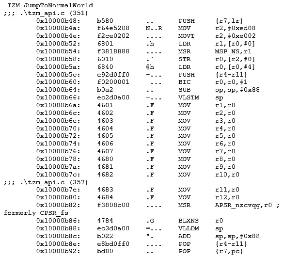
Figure 7.5 – The disassembly contents of TZM_JumptoNormalWorld
The TZM_JumpToNormalWorld(NON_SECURE_START) function – which is defined in the tzm_api.c source file – sets up the non-secure main stack and vector table first. It then gets a pointer to the non-secure resethandler and calls it. The non-secure resethandler function pointer type has __attribute__((cmse_nonsecure_call)). This attribute directs the compiler to generate a BLXNS instruction.
The execution of the BLXNS instruction here at the 0x10000b86 address is important to understand. Normally, you would expect to see a BX LR instruction to return to the calling code, but here, we have the BLXNS r0 instruction, which makes the processor switch from a secure to a non-secure state and branch to the address specified in the r0 register. This instruction was introduced as part of the Armv8-M architecture to enable security state switching. All the MOV rx or r0 instructions before the execution of this BLXNS instruction clear the register’s contents to prevent any possible data leakage from the secure state.
Calling a secure function from a non-secure state
At this point of execution, the processor is in non-secure mode. In non-secure mode, the processor will not be able to access the memory and peripherals of the secure world. The Cortex-M33 processor now executes the non-secure copy of the startup_LPC55S69_cm33_core0.s file and gets to the main() function in the non-secure hello world source file, hello_world_ns.c.
In this main() function, you will see two printf statements first:
    PRINTF_NSE("Welcome in normal world!
");
    PRINTF_NSE("This is a text printed from normal world!
");
The PRINTF_NSE() function – which is defined in veneer_table.c – has __attribute__((cmse_nonsecure_entry)) defined and uses it to call the PRINTF function, which is declared in the secure code. The function was created at secure entry and the attribute is leveraged to call it properly from non-secure mode.
The PRINTF_NSE() function – which is defined in veneer_table.c – has __attribute__((cmse_nonsecure_entry)). This attribute is used to call the PRINTF function, which is declared in the secure code scope. This is an example of using the cmse_nonsecure_entry attribute.
Next, the StringCompare_NSE function is called, which also has the same attribute and is defined in veneer_table.c as well. The function compares two strings by using a non-secure callback. The processor continues to be in a non-secure state when this function is called:
result = StringCompare_NSE(&strcmp, "Test1
", "Test2
");
    if (result == 0)
    {
        PRINTF_NSE("Both strings are equal!
");
    }
    else
    {
        PRINTF_NSE("Both strings are not equal!
");
    }
This example highlights how functions can be called from within the non-secure state, isolated from secure resources.
To investigate the exact instructions being executed, we can inspect the disassembled instructions for these functions from the hello_trustzone.dis file:

Figure 7.6 – The disassembly contents of the Printf_NSE function
Both functions execute an SG instruction. This is a Secure Gateway instruction. As defined in the Armv8-M instruction architecture, non-secure software can only call a secure function if the first instruction is a SG instruction and is in a memory region marked as non-secure callable (as shown in this code example). If these conditions are not met, then it results in a security violation. Because of these strict requirements, non-secure code cannot just jump to the middle of a secure function and run, providing further security isolation.
At the execution of the SG instruction, the processor switches from the non-secure state to a secure state. If you scroll through the disassembly towards the end of execution of the StringCompare_NSE function, you will see a BXNS lr instruction:
       0x10000abc:    4774        tG      BXNS     lr
        0x10000abe:    bf00        ..      NOP
On the execution of this instruction, the processor returns to non-secure mode. The BXNS, BLXNS, and SG instructions are all only available in a secure mode.
Having broken down the key parts of this application, we can let this program run to completion and view the actual program output. If you have not already, run the program by selecting the Run button in µVision. Make sure you are connected to the UART port to view the output coming through; I (Pareena) open the PuTTY tool and connect to UART over COM4 with a speed of 115200, as shown in the following screenshot. For a refresher on connecting to view output, review Chapter 4, Booting to Main:

Figure 7.7 – The PuTTY Configuration window
You should see the following output:
Hello from secure world!
Entering normal world.
Welcome in normal world!
This is a text printed from normal world!
Comparing two string as a callback to normal world
String 1: Test1
String 2: Test2
Both strings are not equal!
As indicated by the printed messages, the overall flow of this application is to boot in the secure world, then switch to the non-secure world to call some secure functions, and finally, exit.
Through this example, we saw in detail how independent secure and non-secure software in the same project interact with and are isolated from one another. Understanding this interaction will help you to implement secure applications based on the PSA’s 10 security goals. The most confusing area of secure software development is often this interaction of secure versus non-secure services and knowing the basic principles involved places you in a good position to develop your own secure applications.
The next example will address how to implement more of the security goals through the PSA reference implementation, TF-M.
Example 2 – TF-M
As noted previously, TF-M is a reference implementation of PSA for Cortex-M-based platforms. TF-M implements PSA developer APIs and has initially been targeted to Armv8-M architecture cores. It is reliant on the isolation boundary between the Secure Processing Environment (SPE) and Non-Secure Processing Environment (NSPE) that we covered in the previous example. It can be broadly broken down into three components.
Let’s review each component in detail:
- Secure boot: TF-M software needs a secure bootloader that authenticates the integrity of the runtime images. This helps achieve Security Goal 4 regarding secure boot. TF-M currently uses a two-stage secure bootloader that validates that the images are from a trustworthy source and only then passes the right of execution to them. This implies all images in TF-M should be hashed and digitally signed for authentication purposes.
TF-M uses MCUBoot as the secure bootloader. MCUBoot is open source and available on GitHub here: https://github.com/mcu-tools/mcuboot. It is automatically downloaded by the TF-M framework during the build process. The public signing keys are built into the MCUBoot bootloader and it allows for separate keys for signing secure and non-secure images.
The following flow describes the secure boot execution by the processor at a high level:
- At reset, the secure boot loader is started. As the name suggests, it runs in a secure mode. It runs the authentication process by verifying the digital signatures in the runtime images.
- On successful validation, it passes control to the secure image, which initializes the environment, including the SAU, the MPU, and secure services. Only after that does it passes control to the non-secure image for execution.
- Secure core: The TF-M core features comprise secure system initialization and secure API calls invoked from both the SPE and NSPE and handled through secure IPC. It also features the Secure Partition Manager (SPM), which creates a database of secure partitions and sets up an isolation boundary between these partitions. A secure partition is a single thread of execution and the smallest unit of isolation. The principles regarding secure versus non-secure software isolation and interaction were discussed in the previous example.
- Secure services: There are several secure services offered through TF-M. The TF-M Cryptographic Secure (TF-M Crypto) service provides a PSA Crypto API implementation in a PSA-RoT secure partition. PSA Secure Storage services provide a key-value storage interface for accessing device-protected storage. Essentially, the TF-M Crypto service allows your software to access common cryptography functions such as hashing and authenticated encryption.
There are two ways to securely store information through TF-M. The PSA Internal Trusted Storage (ITS) is intended to store a small amount of security-critical data, such as cryptographic keys and firmware image hashes. This type of storage is offered by the PSA-RoT as a service and is accessible from the SPE side only.
In contrast, the PSA Protected Storage (PS) is intended to store larger data sets that are stored securely in an external flash, protected against physical attacks. This type of storage is offered at the application-level RoT as a service and is accessible from the NSPE as well as the SPE. It offers data-at-rest protection and can be configured to include device-bound encryption, integrity, or rollback protection.
Important note
More information about these storage types can be found in the PSA Storage API document, currently at version 1.0 at the time of writing: https://armkeil.blob.core.windows.net/developer/Files/pdf/PlatformSecurityArchitecture/Implement/IHI0087-PSA_Storage_API-1.0.0.pdf.
Another secure service offered in TF-M is the TF-M Initial Attestation Service. This service enables a device to prove its identity when needed. It can create tokens on request, containing a fixed set of device-specific items that are used to verify the device’s integrity and trustworthiness by an external verifier.
Important note
There are other services offered by TF-M; a full list for your reference can be found in the TF-M documentation here: https://tf-m-user-guide.trustedfirmware.org/docs/integration_guide/services/index.html.
Now that we have a better understanding of the three TF-M components, let’s walk through the process of building and running TF-M tests on the Corstone-300 FVP running in the AVH AMI.
Obtaining and building the application
The TF-M code described in this section focuses on testing the functionalities of various TF-M components. This includes the secure core component and assorted secure partitions. We can use this test suite to quickly get started with the TF-M code base and subsequently investigate its offerings.
To replicate the example in this section, you will be using the following:
|
Platform |
Corstone-300 AVH |
|
Software |
Trusted Firmware-M |
|
Environment |
AWS EC2 |
|
Host OS |
Ubuntu |
|
Compiler |
Arm Compiler for Embedded |
|
IDE |
- |
Start by launching the AVH AMI and then SSH into the EC2 instance as you have with the examples described in previous chapters. To refresh your memory on this process, you can look at Chapter 4, Booting to Main, in the Arm Virtual Hardware using the Cortex-M55 section, which describes this startup process in detail.
Now, on the EC2 instance running the AVH AMI, follow these commands to update the packages and install some Python prerequisites to build the TF-M suite of tests:
sudo apt update
sudo apt install python3.8-venv
sudo ln -s /usr/local/bin/pip3 /usr/bin/pip3.8
python3.8 -m pip install imgtool cbor2
python3.9 -m pip install imgtool cffi intelhex cbor2 cbor pytest click
Next, we clone the TF-M repository and configure cmake to build the TF-M tests:
git clone https://git.trustedfirmware.org/TF-M/trusted-firmware-m.git
cd trusted-firmware-m
mkdir cmake_build
cd cmake_build
cmake .. -DTFM_PLATFORM=arm/mps3/an552 -DTEST_NS=ON
You can either build all the TF-M tests or select a subset of them to build. The preceding commands include the -DTEST_NS=ON flag, which specifies only building the non-secure suite of tests. There are several different options you can pass to this cmake command to customize the suite of TF-M tests that you would like to run on the Corstone-300 FVP simulation target. They are all documented here: https://tf-m-user-guide.trustedfirmware.org/technical_references/instructions/tfm_build_instruction.html.
As part of the build process, the TF-M tests repo is pulled from https://git.trustedfirmware.org/TF-M/tf-m-tests.git and the configured suite of tests is built. The TF-M test framework consists of both a secure and non-secure test suite, and for now, we are only using the non-secure side. The TF-M tests primarily target the functionality of the TF-M core and secure services API. Some of the checks performed by the TF-M test suite include the following:
- Validating the inter-process communication (IPC) interface between the isolated secure and non-secure firmware partitions as specified by the PSA framework
- Testing the two PSA Storage APIs: PS and ITS APIs
- Testing of the tokens created by the initial attestation service to verify the device identity during the authentication process.
- Validating the TF-M Crypto service, which allows the application to use ciphers, authenticated encryption, or hashes
The best way to look at what each of these tests is doing is by walking through the source code itself. For the IPC non-secure interface test we have just built, you can refer to the source code here: https://git.trustedfirmware.org/TF-M/tf-m-tests.git/tree/test/secure_fw/suites/spm/ipc/non_secure/ipc_ns_interface_testsuite.c. This suite has tests to connect to a secure RoT service from a NSPE or call the secure RoT service over an established connection.
You can inspect other tests in the repository to decide which ones you want to build and test in the same way, or just build them all. After you configure cmake to build the tests you are interested in executing, run the following command to build them:
make install
Upon a successful build, the TF-M test binaries will be created in the bin/ directory. This includes binaries files for the MCUBoot bootloader, TF-M secure firmware, and TF-M non-secure application. Signed variants of both the TF-M secure and non-secure images are created, along with a combined signed image of both the secure and non-secure images.
In addition to the generated binaries, you can run the fromelf command to generate the disassembly files for both the secure and non-secure images:
fromelf –c tfm_s.axf > tfm_s.dis
fromelf –c tfm_ns.axf > tfm_ns.dis
We will use the disassembly files later in the example to inspect the instructions generated by the compiler for some of the test function calls.
Running the test suite
Now that we have successfully built the TF-M non-secure suite of tests, we are ready to run it on the Corstone-300 FVP that is already installed on the AMI.
Use this command to launch the simulation:
VHT_Corstone_SSE-300_Ethos-U55 -a cpu0*="bin/bl2.axf" --data "bin/tfm_s_ns_signed.bin"@0x01000000
The bl2.axf file is the MCUBoot bootloader image that runs on the Cortex-M55 in the Corstone-300 FVP. tfm_s_ns_signed.bin is the combined signed image for the TF-M secure and non-secure image, and the address after the @ sign indicates where in the Corstone-300 FVP memory the image is loaded.
For your reference, the memory map for the FVP is documented here: https://developer.arm.com/documentation/100966/latest/Arm--Corstone-SSE-300-FVP/Memory-map-overview-for-Corstone-SSE-300.
The memory in the FVP is aliased for secure and non-secure usage. This is per the memory aliasing concept that was introduced with the Armv8-M architecture. To determine whether it is a secure or non-secure partition, bit 28 of the address is used by the memory protection controller on the system. What this implies is that the contents of 0x01000000 are the same as 0x11000000, with the former being secure and the latter non-secure.
On running the preceding command, you should see a successful simulation run, which will output the PASSED status on each individual test. A summary similar to the one shown here is printed at the end of the simulation:
*** Non-secure test suites summary ***
Test suite 'IPC non-secure interface test (TFM_NS_IPC_TEST_1XXX)' has PASSED
Test suite 'PSA protected storage NS interface tests (TFM_NS_PS_TEST_1XXX)' has PASSED
Test suite 'PSA internal trusted storage NS interface tests (TFM_NS_ITS_TEST_1XXX)' has PASSED
Test suite 'Crypto non-secure interface test (TFM_NS_CRYPTO_TEST_1XXX)' has PASSED
Test suite 'Platform Service Non-Secure interface tests(TFM_NS_PLATFORM_TEST_1XXX)' has PASSED
Test suite 'Initial Attestation Service non-secure interface tests(TFM_NS_ATTEST_TEST_1XXX)' has PASSED
Test suite 'QCBOR regression test(TFM_NS_QCBOR_TEST_1XXX)' has PASSED
Test suite 'T_COSE regression test(TFM_NS_T_COSE_TEST_1XXX)' has PASSED
Test suite 'TFM IRQ Test (TFM_IRQ_TEST_1xxx)' has PASSED

*** End of Non-secure test suites ***
Analyzing a RoT service connection test
Let us inspect one of the tests we have run to understand the program flow a little better. We will look at the tfm_ipc_test_1003 test in https://git.trustedfirmware.org/TF-M/tf-m-tests.git/tree/test/secure_fw/suites/spm/ipc/non_secure/ipc_ns_interface_testsuite.c.
This test checks the connection of the NSPE to a RoT Service using its secure function ID (SID). This is the test source code:
static void tfm_ipc_test_1003(struct test_result_t *ret)
{
    psa_handle_t handle;

    handle = psa_connect(IPC_SERVICE_TEST_BASIC_SID,
                         IPC_SERVICE_TEST_BASIC_VERSION);
    if (handle > 0) {
        TEST_LOG("Connect success!
");
    } else {
        TEST_FAIL("The RoT Service has refused the connection!
");
        return;
    }
    psa_close(handle);
    ret->val = TEST_PASSED;
}
Both the NSPE and SPE use the following APIs to call the RoT secure services:
- psa_connect: This API is used to connect to a RoT secure service by its SID
- psa_call: This API calls a RoT secure service on an established connection
- psa_close: This API is used to a close a connection to the RoT secure service
The psc_connect() API calls the tfm_ns_interface_dispatch() function, which takes the SID and version, as shown in the function here:
psa_handle_t psa_connect(uint32_t sid, uint32_t version)
{
    return tfm_ns_interface_dispatch(
                                (veneer_fn)tfm_psa_connect_veneer,
                                sid,
                                version,
                                0,
                                0);
}
The tfm_ns_interface_dispatch() function then creates a lock around this critical section of code and the API call structure is sent to the secure veneer function, tfm_psa_connect_veneer.
Inspect the tfm_s.dis disassembly file we generated for the secure image. You will see that this veneer function uses a SG instruction to enter secure mode before branching to the actual function, __acle_se_tfm_psa_connect_veneer, in the secure partition code:

Figure 7.8 – The disassembly contents of tfm_psa_connect_veneer function
The principle is the same as we saw in the previous section with the simple hello world TrustZone example. When non-secure code calls a secure function, it executes a SG instruction in a special veneer region first and only then branches to the secure function code.
Now, the API call is sent to the SPM. A handle for the connection is returned – the mutex around this critical code is also released:

Figure 7.9 – The disassembly of tfm_psa_connect_veneer and return to non-secure
At the end of the execution of this secure function, a BXNS lr instruction is executed, as shown in the disassembly. This causes a branch to the link register and a transition from the secure function code back to the non-secure code.
A similar program flow is followed to then close the connection to the RoT by calling the psa_close function. Upon a successful connection opening and closing, the test passes.
This TF-M example suite of tests, and the TF-M code base in general, is a powerful resource for understanding how to implement secure software on Cortex-M processors. You can use it as the foundation for your secure device or simply as an example reference to learn from. To leverage TF-M right away for your device, check to see whether your hardware is on the supported platform list: https://tf-m-user-guide.trustedfirmware.org/platform/index.html. If it is not, there are detailed instructions on how to add a new platform for TF-M support located here: https://tf-m-user-guide.trustedfirmware.org/integration_guide/platform/index.html.
Basing your software on TF-M and selecting a PSA Certified SoC or device are excellent ways to meet the PSA 10 security goals and build security directly into your device from the start.
Summary
This chapter outlined the security landscape for Cortex-M-based systems. We looked at the PSA framework first, which offers guidelines on how to systematically build security into your device. The first step is to analyze threats to understand the level of security needed for your specific use case. The second step is to architect a solution to plan what security needs to be implemented and how. The third step is to implement, build, or integrate your defined solution. The fourth step is to optionally certify your device’s security.
We then implemented a secure versus non-secure state interaction through a hello world example on a Cortex-M33, breaking down how the two states manage interaction securely. Finally, we implemented a TF-M software test suite on a Cortex-M55, analyzing more security implementations in a realistic context.
Implementing proper security on Cortex-M devices can be a tricky undertaking. With the skills learned and resources available in this chapter, however, you are well positioned to ensure your next Cortex-M-based device is properly secured.
These past four chapters (Chapter 4, Booting to Main; Chapter 5, Optimizing Performance; Chapter 6, Leveraging Machine Learning; and Chapter 7, Enforcing Security) have all focused on delivering quality software by offering good coding practices, helpful libraries, and development frameworks. The next two chapters will focus on delivering quality software through a different means: useful development techniques. Up next, we discuss how to utilize the tools and services available through popular cloud providers to streamline your embedded development.
Further reading
To learn more about the topics that were covered in this chapter, take a look at the following resources:
- ARMv8-M Security Extensions: Requirements on Development Tools – Engineering Specification: https://developer.arm.com/documentation/ecm0359818/latest/
- Secure software guidelines for Armv8-M: https://developer.arm.com/documentation/100720/0300
- TF-M documentation: https://tf-m-user-guide.trustedfirmware.org/
- PSA Certified 10 goals explained: https://www.psacertified.org/blog/psa-certified-10-security-goals-explained/
- A guide on the TrustZone technology for Armv8-M architecture: https://developer.arm.com/documentation/100690/latest/