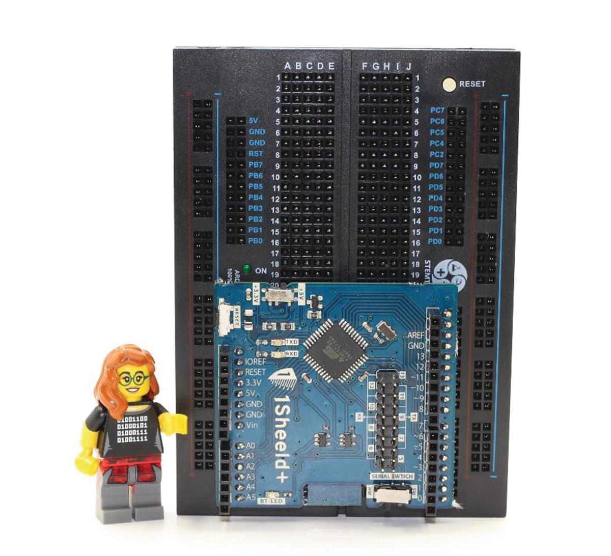
Arduino shields can offer sophisticated functionality, such as the connection to a smartphone that will be explored in this chapter. The shield to accomplish this connection to a smartphone is the 1Sheeld+, shown in Figure 12-1. This shield features a Bluetooth connection between the smartphone and the Arduino, as well as an app for the smartphone to facilitate connection. Much of the functions and sensors built into a smartphone can be accessed through the Arduino and hence also to LEGO MINDSTORMS. Two projects are built in this chapter. The first, called the Tilt Mimic, will use a LEGO motor to tilt a Technic liftarm to the same angle of orientation of the phone. The second invention, called the Intrusion Monitor, uses a MINDSTORMS Ultrasonic Sensor as a trigger for a smartphone to take a picture and send a notification email message.
Figure 12-1
The 1Sheeld+ sets up a Bluetooth communication link between the Arduino and a smartphone
Mounting the 1Sheeld+
The 1Sheeld+ comes delivered with headers already installed, with no need to solder headers in place as was required in Chapters 10 and 11. Instead, the installation of the 1Sheeld+ proceeds by simply pressing it into place on the Arduino, as shown in Figure 12-2.
Figure 12-2
The 1Sheeld+ mounts onto the Arduino
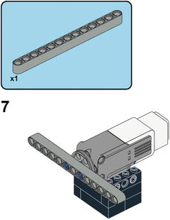
Building the Tilt Mimic
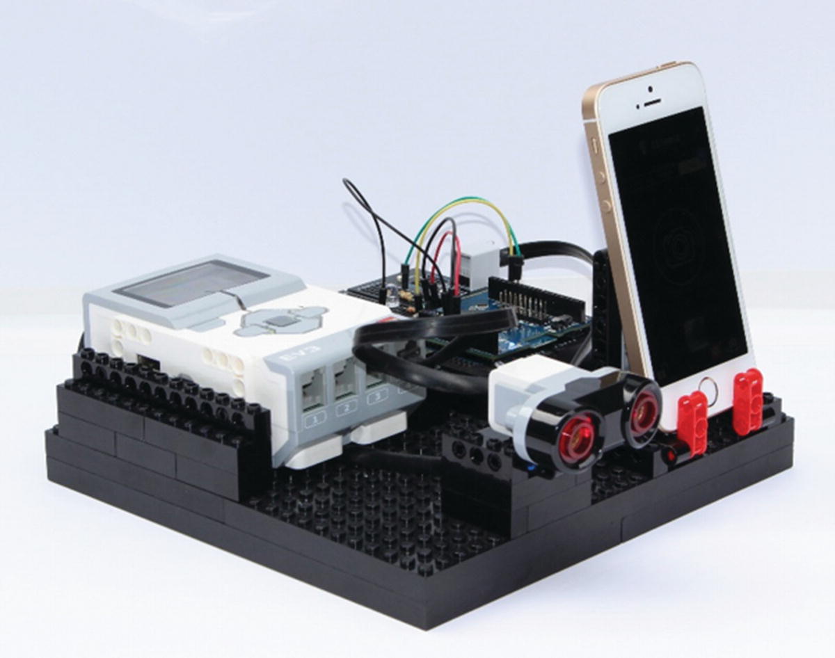
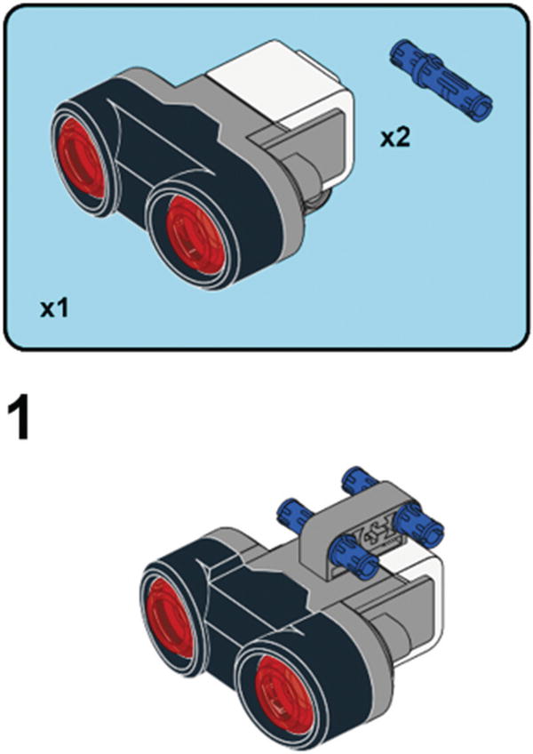
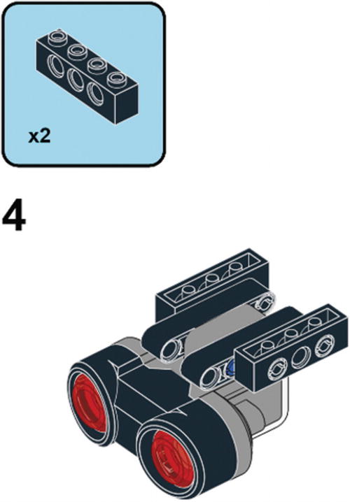
The Tilt Mimic, shown in Figure 12-3, orients a Technic liftarm to the same angle measured by a smartphone. As the smartphone is tilted, an EV3 Medium Motor will go to the same angular orientation as the smartphone. Building instructions for the motor mount are shown after Figure 12-3.
Figure 12-3
The Tilt Mimic rotates a Technic liftarm to the same angular orientation as a smartphone
Wiring Connections for the Tilt Mimic
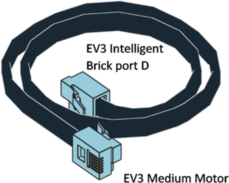
As with the shields used in Chapters 10 and 11, most of the wiring connections for the 1Sheeld+ are made by the headers of the 1Sheeld+ pressed into the Arduino. The remaining connection is an I2C link to pass data from the Arduino to the EV3 Intelligent Brick via the Breadboard Connector—a diagram of this I2C wiring connection is given in Figure 12-4. An additional cable connection, diagrammed in Figure 12-5, connects the EV3 Intelligent Brick to an EV3 Medium Motor.
Figure 12-4
Communication between the Arduino and the EV3 Intelligent Brick is by I2C
Figure 12-5
An EV3 Medium Motor is connected to port D of the EV3 Intelligent Brick
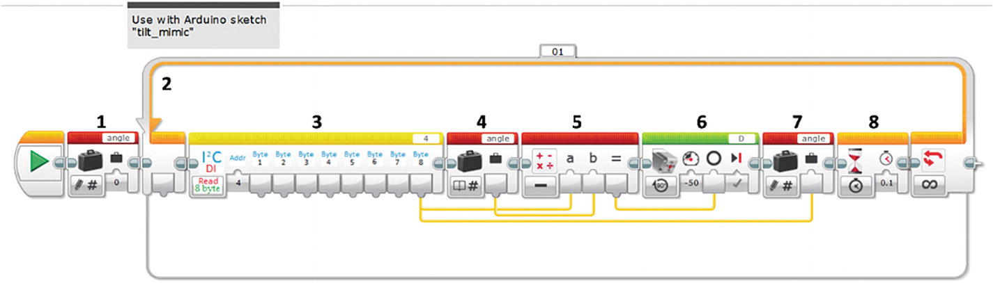
EV3 Code for the Tilt Mimic
The purpose of the EV3 code, shown in Figure 12-6, is to take in I2C data from the 1Sheeld+. This data is of the angular orientation of a smartphone, which the EV3 Intelligent Brick interprets into a setting to send to an EV3 Medium Motor. As the angle of the smartphone is changed, the EV3 motor will orient itself to the same angle. The result is that a Technic liftarm attached to the motor will always be parallel to the angle of the smartphone.
Figure 12-6
The EV3 program for the Tilt Mimic reads in data over I2C connection
Functions for each of the programming blocks in Figure 12-6 include
1.
Variable Block: Loads a starting point for a variable called angle to a setpoint of 0.
2.
Loop Block: Sets up an infinite loop to read in the orientation angle of the smartphone and continuously update the orientation of an EV3 motor.
3.
I2C Block: Reads 1 byte of information from the I2C connection to the smartphone. Only 1 byte of the 8 possible bytes is used in this project.
4.
Variable Block: Reads the value stored in the variable angle.
5.
Math Block: Calculates the difference between the current and the prior orientation angle of the smartphone. If the smartphone has not changed in angle, the results of the calculation will be zero, meaning no change is made to the EV3 Medium Motor.
6.
Medium Motor Block: Applies an angle of rotation to the motor, as calculated in block 5.
7.
Variable Block: Updates the value of the variable angle to the current orientation of the smartphone.
8.
Wait Block: Pauses for 0.1 second to avoid oversampling the I2C communication link.
Arduino Sketch for the Tilt Mimic
The Arduino sketch, shown in Listing 12-1, to monitor the angle of the smartphone makes use of libraries developed by 1Sheeld, available at www.1sheeld.com/downloads/.
Serial.println(OrientationSensor.getY()); //Print orientation as diagnostic
c[0] = OrientationSensor.getY(); //Store orientation in variable
Wire.onRequest(sendData); //Send data to EV3
delay(100);
}
//Function for sending data
void sendData()
{
Wire.write(c,8); //c is the array of 8 bytes length.
}
Listing 12-1
The Arduino sketch for using the 1Sheeld+ should be run at the same time as the EV3 program “orientation”
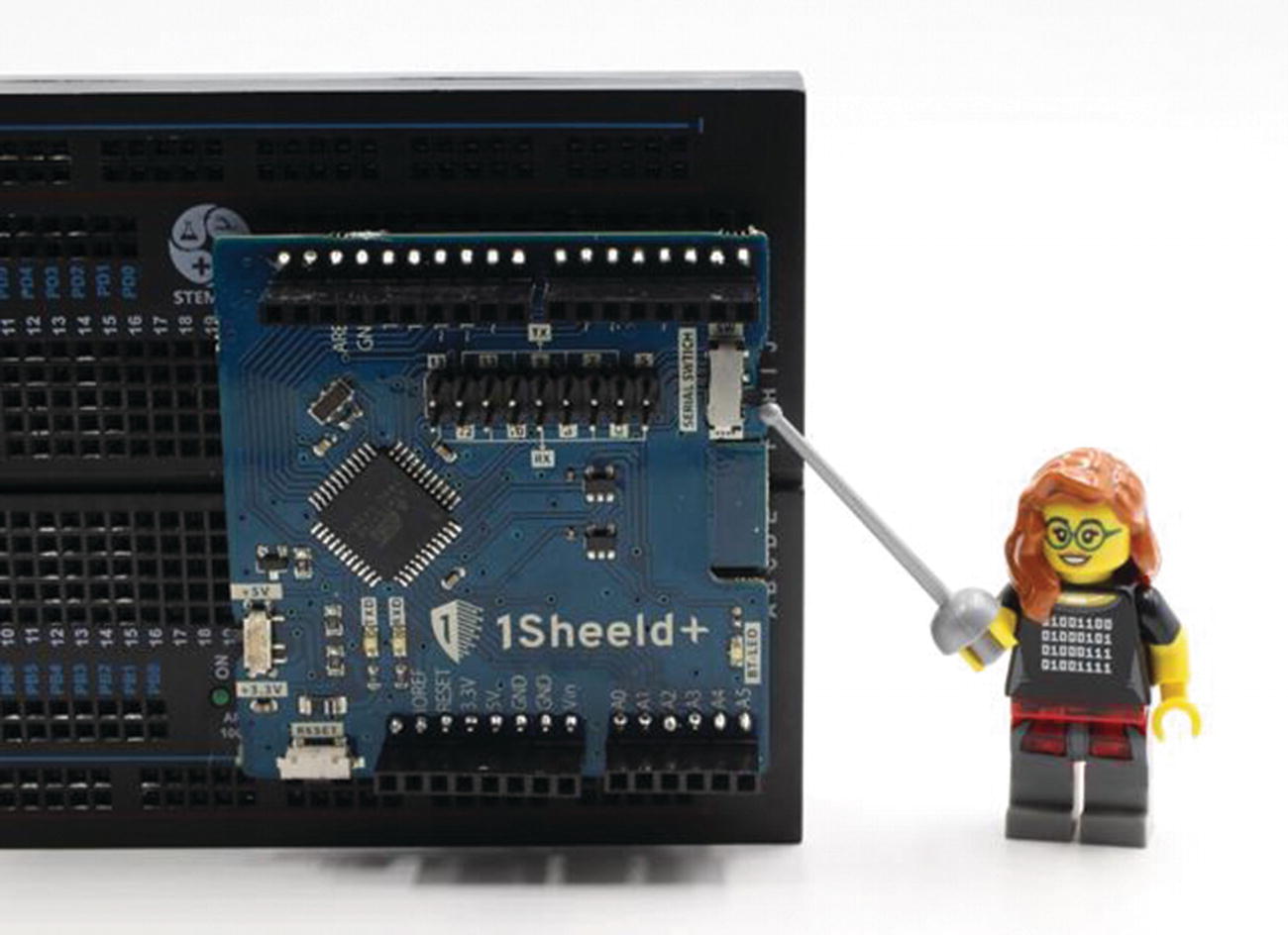
In order to load the sketch onto the Arduino, a switch on the 1Sheeld+ board must be set into the “SW” position. The location of this switch is shown in Figure 12-7. After uploading the Arduino sketch, this switch should be placed into the “HW” position.
Figure 12-7
The serial switch on the 1Sheeld+ must be set to “SW” when loading a sketch, then “HW” when running the sketch
Setting Up the Smartphone for the Tilt Mimic
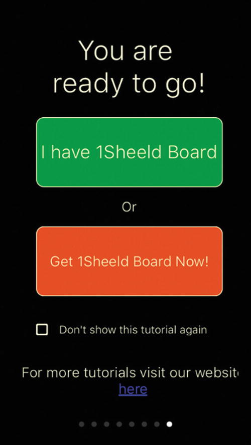
The 1Sheeld+ is set up and controlled by an app installed on a smartphone, available at www.1sheeld.com/downloads/. To initiate the Tilt Mimic, the functions of Email and Orientation are activated on this app. Screenshots of this setup are shown in Figures 12-8 to 12-12.
Figure 12-8
Press “I have 1Sheeld Board” to begin the setup of the 1Sheeld app
Figure 12-9
Press inside the purple line of the “Scan” circle for the smartphone to find the 1Sheeld+ link
Figure 12-10
Press the name of the found 1Sheeld+ (“1Sheeld#NI” in this example) to establish the Bluetooth link between the smartphone and the 1Sheeld+
Figure 12-11
Select the “Orientation” shield. Then press the small shield symbol in the upper left corner of the screen
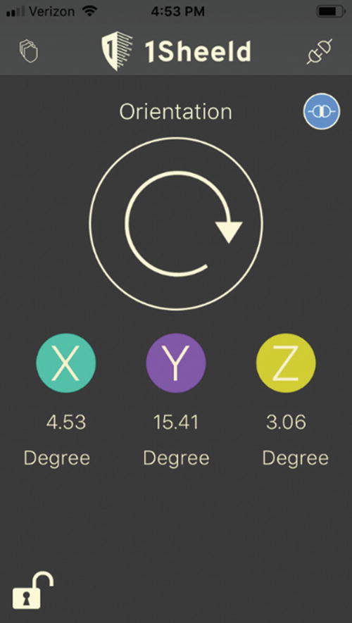
Figure 12-12
Orientation measurements are displayed on the smartphone screen—the Y axis is used in the Tilt Mimic
Running the Tilt Mimic
Before running the Tilt Mimic, the angle of the Technic liftarm connected to the EV3 Medium Motor should be set to horizontal—this can be done by simply taking hold of the liftarm and rotating it. This action sets the zero-degree starting point for tilt. To run the Tilt Mimic, three programs should be running:
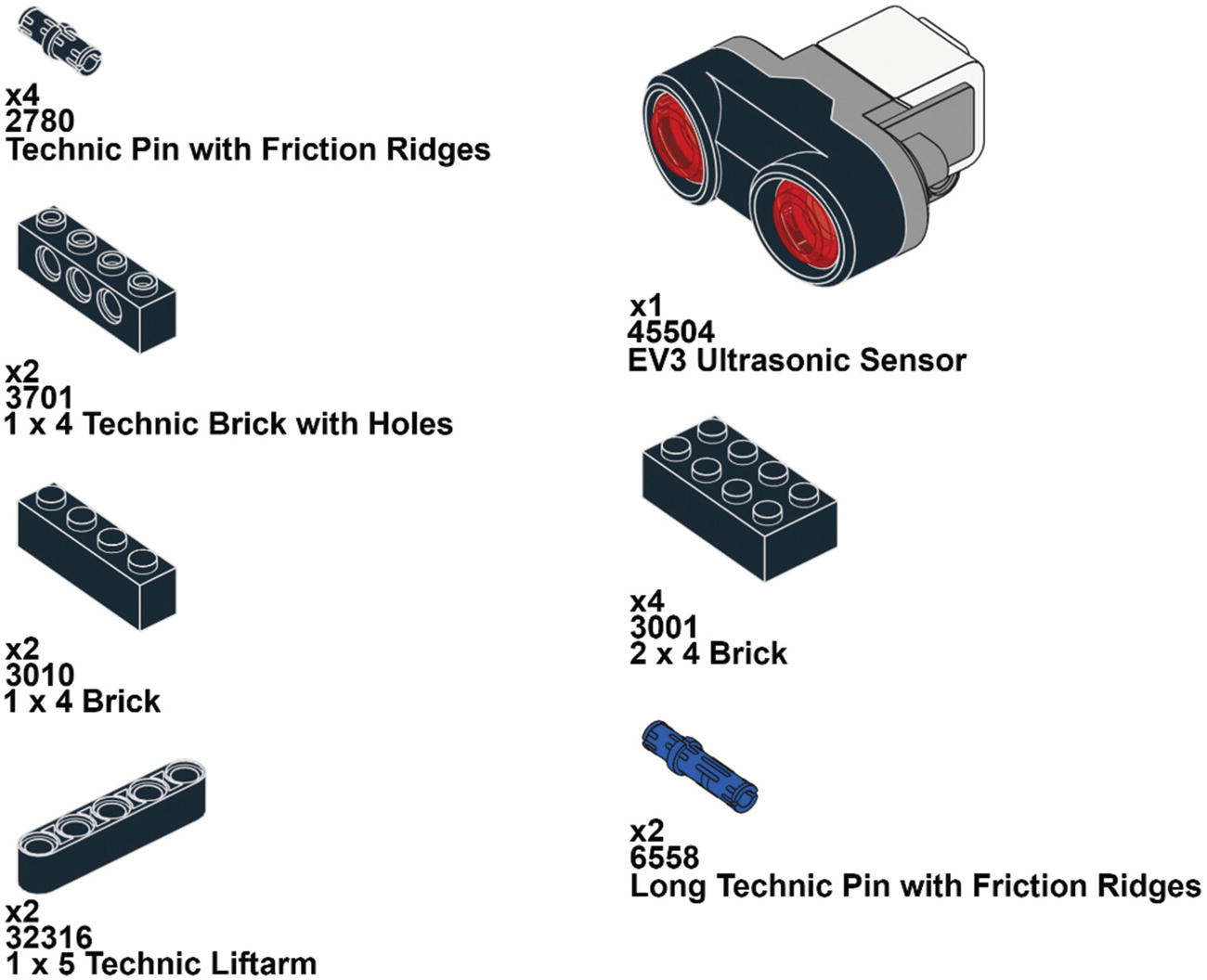
The Intrusion Monitor, shown in Figure 12-13, detects when someone or something is within 50 cm of the EV3 Ultrasonic Sensor. When this proximity is triggered, the smartphone takes a photograph and sends an email notification. There are two parts to build: sensor mount and smartphone stand.
Figure 12-13
The Intrusion Monitor detects objects with the EV3 Ultrasonic Sensor
Building the Intrusion Monitor—Sensor Mount
The Ultrasonic Sensor Mount serves to hold the EV3 Ultrasonic Sensor, as built in the following steps.
Building the Intrusion Monitor—Smartphone Stand
The smartphone stand gives a place for the phone to rest, with the camera facing in the same direction as the EV3 Ultrasonic Sensor. Building instructions are given as follows.
Wiring the Intrusion Monitor
The control signal from the EV3 Intelligent Brick to the Arduino is a digital pulse, created by adapting a motor control signal in the EV3 programming environment. This digital pulse indicates when the Arduino should initiate actions, in this case, to have the smartphone (via the 1Sheeld+) take a photograph and send an email. Figure 12-14 shows the circuit and wiring connections to make for the digital pulse control signal. I2C is not used here for this communication link because doing so creates signal conflicts with the 1Sheeld+. The voltage taken from AN IN on the Breadboard Connector has a voltage level too high to work with the Arduino, posing a risk of damaging the Arduino. So a pair of resistors is used in a voltage divider circuit to lower the voltage to about 4 volts.
Figure 12-14
Wiring for the Intrusion Monitor includes two circuits: a voltage divider to input to Arduino pin 12 and an LED on Arduino pin 13
The circuit of Figure 12-14 also includes an LED connected to pin 13 of the Arduino to give an indication of when an event has been triggered by the EV3 Intelligent Brick. The LED will light up for the duration of the pulse created by the EV3 program, providing a confirmation that the setup is working. The Breadboard Connector is then connected with the EV3 Intelligent Brick port A, as per the diagram in Figure 12-15. Also shown in Figure 12-15 is another EV3 connection between the Intelligent Brick port 4 and the Ultrasonic Sensor.
Figure 12-15
EV3 cables connect to the Ultrasonic Sensor and the Breadboard Connector
EV3 Code for the Intrusion Monitor
The function of the EV3 program for the Intrusion Monitor, shown in Figure 12-16, is to create a digital pulse if something comes within a certain distance of the Ultrasonic Sensor. The digital pulse is created by repurposing an Unregulated Motor block. A power setting of 100% on this block will create a 7.5V signal on the AN IN pin of the breakout board. The voltage drops to zero when the motor is shut off by the Unregulated Motor block.
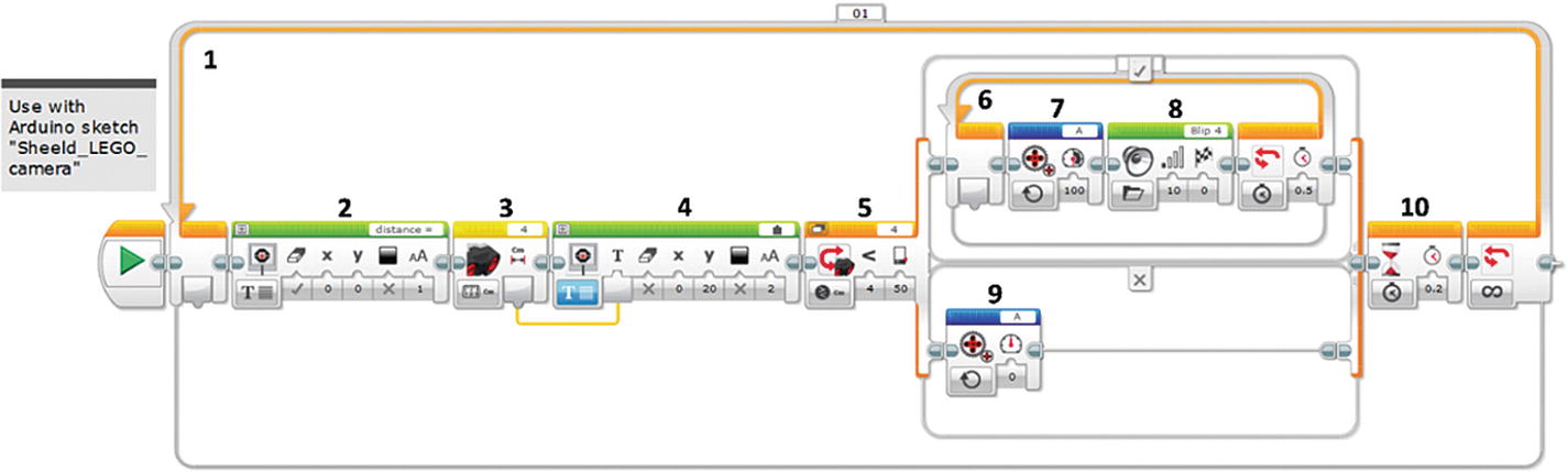
Figure 12-16
The EV3 program for the Intrusion Monitor uses an Ultrasonic Sensor as a trigger
Steps in the EV3 code include
1. Loop Block: Creates an infinite repetition of monitoring the output of the EV3 Ultrasonic Sensor.
2. Display Block: Prints a label on the EV3 Intelligent Brick’s front panel display as a reminder of the quantity being measured.
3. Ultrasonic Sensor Block: Takes a distance reading from the EV3 Ultrasonic Sensor.
4. Display Block: Prints the measurement results of block 3 to the front panel display.
5. Switch Block: Based on the EV3 Ultrasonic Sensor, executes blocks 6–8 to generate the digital pulse and play a sound if an object is found within 50 cm of the sensor. Otherwise, if nothing is detected, block 9 is run to reset the output to 0 V.
6. Loop Block: Keeps blocks within it active for 0.5 seconds.
7. Unregulated Motor Block: Turns on a digital pulse connected to port A. There is no motor connected to port A, but rather a wire connection to access the digital signal.
8. Sound Block: Gives an audible signal that an intruder has been detected.
9. Unregulated Motor Block: Ensures that the digital pulse is off, in the event that nothing has been detected by the EV3 Ultrasonic Sensor.
10. Wait Block: Pauses operation for 0.2 seconds to avoid signals being confused between the Arduino and the EV3 Intelligent Brick.
Arduino Sketch for the Intrusion Monitor
When triggered by a digital pulse input on pin 12, the Arduino executes commands to the 1Sheeld+ to have the smartphone take a photograph and send a notification email. The sketch is shown in Listing 12-2.
int buttonPin = 12; //Set input pin, connected to EV3 Intelligent Brick
int ledPin = 13; //Set output pin, connected to LED
void setup()
{
OneSheeld.begin(); //Start 1Sheeld communications
pinMode(buttonPin,INPUT); //Set button pin as input
pinMode(ledPin,OUTPUT); //Sets LED pin as output
}
void loop()
{
if(digitalRead(buttonPin) == HIGH) //Checks the digital input state
{
digitalWrite(ledPin,HIGH); //Turn on LED
Camera.frontCapture(); //Take a picture with front camera
Email.send("[email protected]","Intruder!", "I took a picture of intruder!"); //Send email
OneSheeld.delay(10000); //Wait for 10 seconds
}
else
{
digitalWrite(ledPin,LOW);//Turn off LED
}
}
Listing 12-2
The Arduino sketch for using the 1Sheeld+ for the Intrusion Monitor should be run at the same time as the EV3 program “ultrasonic_trigger”
Setting Up the Smartphone for the Intrusion Monitor
The app for 1Sheeld+ on the smartphone needs to have shields activated for Email and Camera, as shown in Figure 12-17. The steps prior to selecting these two shields are the same as for the Tilt Mimic in Figures 12-8 to 12-10. The Email function on the 1Sheeld+ only works with Gmail accounts, so such an account may have to be created at www.gmail.google.com.
Figure 12-17
Shields for Camera and Email should be selected on the 1Sheeld+ app
Running the Intrusion Monitor
Three programs should be running for the activation of the Intrusion Monitor:
“ultrasonic_trigger” on the EV3 Intelligent Brick
“Sheeld_LEGO_camera” on the Arduino
Camera and Email on the 1Sheeld+ app of the smartphone
Notice must also be taken that the switch on the 1Sheeld+ should be in the “HW” position. When an object gets within 50 cm of the EV3 Ultrasonic Trigger, the sound should play on the EV3 Intelligent Brick, and the LED connected to Arduino pin 13 should light up. The smartphone, with the 1Sheeld+ app running, should show a notification at the bottom of the screen that an email message has been generated. There’s then a delay of about 7 seconds before the smartphone takes a picture, which shows up as a thumbnail image at the bottom of the smartphone screen. Photographs are stored on the smartphone at the same location as all of the photos on the phone.
Summary
This chapter used an Arduino shield to interface LEGO MINDSTORMS with a smartphone. The functionality of the smartphone can be accessed through MINDSTORMS, including the many sensors imbedded in the phone and communications. Two projects were built, using the 1Sheeld+, to demonstrate the MINDSTORMS/smartphone interface. The first project tilted a LEGO motor to the same angular orientation of the smartphone. The second project used the capability to access multiple smartphone functions, in this case email and camera. A LEGO EV3 Ultrasonic Sensor served as a sensor to detect intruders, which when triggered had the smartphone take a photograph and send a notification email. The 1Sheeld+ has many other functions that can be explored for even more sophisticated inventions, such as the use of voice recognition or cellular telephone calls.