Chapter 7. Error Handling
A typical LabVIEW application controls instrumentation while acquiring, analyzing, displaying, and logging data—hence, the marketing slogan: Acquire, Analyze, and Present. Things can go wrong, however, regardless of the graphical programming methodology, application complexity level, and developer skill level. LabVIEW applications execute exactly as programmed and are not immune to bugs. The complexity of the applications LabVIEW is applied to is ever increasing. Also, in the dynamic world we live in, applications can begin misbehaving long after they are tested and deployed. For example, an instrument might hang up or become disconnected, or changes to the target computing device might cause a resource conflict, or a network directory path might change. Even if the application is completely bug-free at the time of deployment, it will not overcome the unexpected without an effective error handling scheme. Moreover, how quickly the developer and the application’s users can identify and correct any problems that arise depends on how well the application incorporates error handling.
Error handling is an essential part of all LabVIEW applications and serves multiple purposes, from development through deployment. First, error handling is imperative for debugging an application. When the application reports an error, we can quickly identify and correct many problems based on the error data. Error handling helps identify and describe errors long before we might otherwise observe the application misbehaving. Debugging an application without error handling is analogous to graphical programming wearing a blindfold. It is extraordinarily difficult to locate the source of most problems without good error handling.
After an application has been debugged, error handling helps test the limits of the application’s capabilities. During testing, one may experiment with the maximum number of channels, fastest acquisition rate, most demanding analysis routine, fastest user interface update and disk streaming rates, or test the most unlikely combination of operator inputs. Error handling can tell us when something goes awry and pinpoint the operation that reports a problem. The application can be finetuned, such as setting the Data Range property of numeric controls, to help prevent invalid user inputs that may cause misbehavior.
When an application contains complete error handling, is thoroughly tested, and does not generate errors, we may rest assured that it is a reliable application. After deployment, the error handling must remain intact to report any new problems that may arise due to unforeseen circumstances. Many factors are beyond LabVIEW’s control. Changes to the computing device’s hardware, software, or network configuration are common sources of new misbehavior to an otherwise bug-free application. The presence of thorough error handling helps users and developers quickly identify and resolve new problems. Hence, thorough error handling serves the purpose of preventative maintenance in our applications.
Not only is error handling important for identifying problems, but error handling also is directly related to good LabVIEW programming style. As discussed in Chapter 4, “Block Diagram,” data flow is the fundamental principle of LabVIEW, and propagating the error cluster is the primary means of establishing data flow. The error clusters are LabVIEW’s most universally recognized data structure on a VI’s front panel, connector pane, and diagram. Put them to good use!
7.1 Error Handling Basics
An error is a failure of a function or VI to complete its programmed task. Most nodes in LabVIEW propagate error data using the error in and error out clusters. The error clusters consist of a Boolean for the status, an integer for the code, and a string for the source, and are located in the Array, Matrix & Cluster controls palette. The status uniquely indicates whether an error has occurred. The code identifies the type of error and is used by the error reporting VIs to look up a corresponding description. The source identifies the function or VI that generates the error. The error cluster’s default value consists of status = FALSE, code = 0, and source = <empty string>, indicating no error or warning. If the status is FALSE but the code is nonzero and the source is not empty, then a warning occurred. A warning is similar to but considered less severe than an error. For example, the node is successful at performing its programmed task, but there is something unusual about the input values or result.
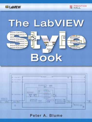
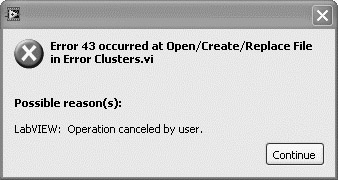
Examples of the error out cluster containing no error, a warning, and an error are provided in Figure 7-1. The default no error value is shown on the left. The warning shown in the middle is commonly returned from a successful call to VISA Read. It indicates that the number of bytes transferred is equal to the requested input count, but more data might be available. The error cluster on the right contains error code 43, indicating that the user canceled the operation. This is a very common error that occurs when a file dialog is canceled. Most VIs have one error in control and one error out indicator, assigned to the lower left and right connector terminals, respectively.
Figure 7-1. The error out clusters indicate no error or warning on the left, a warning in the middle, and an error on the right.

Rule 7.1
![]()
All VIs must trap and report the errors returned from error terminals
Error handling involves trapping and reporting the errors returned from the functions and VIs that have error terminals. Trapping is capturing the error returned from each node’s error out terminal. Reporting involves displaying or logging the error information using a dialog or log file. Thorough trapping and reporting of errors is the best means by which errors are handled. This section presents error handling basics, including rules, techniques, and illustrations for trapping and reporting errors. Error codes and ranges are also discussed.
7.1.1 Trapping Errors
Rule 7.2
![]()
Trap errors by propagating the error cluster among the error terminals
Errors are trapped by propagating the error cluster among the nodes that have error terminals, throughout every VI in an application. Begin by placing the error in control and error out indicator on the panel of each VI, or simply use a template that has been prepopulated with these controls. On the diagram, lay out the nodes into data or sequence dependent groups, positioned from left to right in the order they will execute. Use the vertical alignment tools in the Align Objects pull-down menu to align the icons and simplify wiring. Use the horizontal distribution tools from the Distribute Objects pull-down menu to space the nodes for adequate terminal access. Each group of sequential nodes comprises an error chain.
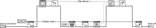
Initiate a wire from the error in control terminal to the error in connector terminal of the first node in each error chain. Wire the node’s error out terminal to the next node’s error in terminal, and repeat until all of the error terminals are wired, with the exception of the last node of each error chain’s error out terminal. For a VI with a single error chain, wire the last node’s error out terminal to the error out indicator terminal or to an appropriate error reporting subVI. If a VI has multiple error chains, merge the error out terminals from the last node in each chain using Merge Errors VI. Figure 7-2 illustrates a simple error chain made up of File I/O nodes. Figure 7-3 contains two parallel error chains, including DAQmx VIs and File I/O nodes.
Figure 7-2. The error cluster propagates among several File I/O nodes to form an error chain.
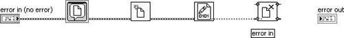
Figure 7-3. DAQmx VIs and File I/O nodes form two separate parallel error chains that are combined using Merge Errors VI.

Most functions and VIs that LabVIEW provides are designed to check the error status from the error in terminal and, if an error exists, skip their code and pass the same error information straight through their error out terminal. Hence, once an error occurs, the successive nodes of an error chain propagate the error information throughout the chain. This is desirable because the nodes of an error chain are generally related and interdependent. In the File I/O example of Figure 7-1, the file writing operation is dependent on a valid file reference number returned by Open/Create/Replace File, which itself is dependent on a valid file path returned by the File Dialog Express VI. An error generated by one prevents the subsequent nodes from succeeding. As long as all error terminals are properly wired, the first error that occurs is trapped within the chain of nodes and wires.
As discussed in Chapter 4, propagating the error cluster creates data dependency, which determines the order in which the nodes execute on the diagram. Data dependency is an underlying principle of data flow. Therefore, it is also important to wire the error cluster to nodes to specify the desired execution order. However, the most common mistake I observe in practice is incomplete error trapping. It seems that many developers propagate the error cluster for data dependency but fail to fully trap and report the errors. This is evident when the error cluster propagates between the functions requiring an order dependency but is not shared among the remaining functions or terminated appropriately.
Rule 7.3
![]()
Trap errors from all iterations of loops
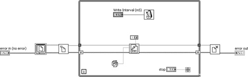
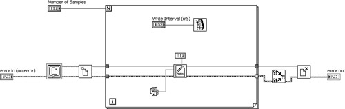
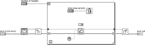
Special considerations are required with looping structures. It is important to examine the data flow and loop condition to see if the error is being trapped within all iterations. In Figure 7-4A, there is continuity between the error in control terminal, the error connector terminals on the File I/O nodes, and the error out indicator terminal. At first glance, the error appears to be trapped, but it is not. Instead, the loop input tunnel resets the error data within each new iteration of the loop. Also, the error data passed to the loop’s output tunnel is overwritten in each successive iteration. Only the error data from the last iteration of the loop passes through the output tunnel. Hence, the error chain does not remember any errors that may have occurred in any of the iterations prior to the last. Two better alternatives are to either terminate the loop upon the first occurrence of an error or maintain the error data between successive iterations via a shift register. These alternatives are shown in Figures 7-4B and 7-4C. The former solution stops the loop immediately if an error occurs; the latter continues the loop but skips all successive File I/O operations. In both scenarios, the error is trapped and eventually passes through the While Loop to the error out indicator terminal upon loop completion.
Figure 7-4A. Error data from the While Loop’s input tunnel resets the error data, and error data from the file writing operation overwrites the output tunnel data within each successive iteration of the loop.
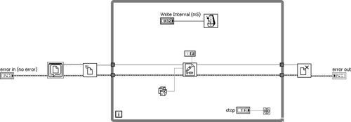
Figure 7-4B. The error status is checked within each iteration of the While Loop, and the loop is terminated if an error occurs. Any error is successfully trapped within the error chain and passes through the output tunnel to the error out indicator terminal.
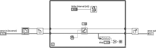
Figure 7-4C. A shift register is used to propagate the error data between successive iterations of the loop. If an error occurs, the loop continues but the file writing function skips its operation.
Note that For Loops execute a predetermined number of iterations, cannot be terminated prematurely, and have indexing enabled on their output tunnels by default. This means that an error cluster passed through an output tunnel will accumulate into an array of size equal to the count. If you have a good reason to accumulate all the errors and the loop count is limited, index the errors. Outside the For Loop’s output tunnel, the Merge Errors VI can process the array of errors, as shown in Figure 7-5A. Merge Errors VI searches the array and returns the first element with status = TRUE, or no error. Indexing should never be enabled within continuous loops, however, because the array size is unbounded.
Figure 7-5A. A For Loop indexes an array of errors by default. Merge Errors VI returns the first element of the array with status = TRUE.
Similar to the While Loop, the shift register method of error trapping is the best method of propagating the error data between successive For Loop iterations. This is shown in Figure 7-5B. The shift register method maximizes efficiency in the event of an error because the functions and VIs that receive an error at their error in terminal skip their code. Also, the shift register method maximizes memory efficiency because it maintains the data from only one error cluster in memory. Moreover, the shift register extends a continuous error chain throughout the loop, whereas indexing resets the error chain in each new iteration. Consequently, the shift register method is generally preferred over the index array method.
Figure 7-5B. A shift register extends the error chain between iterations of the loop. This approach is more efficient than array indexing.
Many VIs of medium or greater complexity benefit from parallel error chains, similar to what is illustrated in Figure 7-3. Parallel error chains are particularly useful when the parallel chains of nodes share common data, such as an I/O name or reference number. For example, in Figure 7-3 a task is propagated among the DAQmx VIs, and a file reference number is propagated among the File I/O functions. Positioning these groups of nodes in parallel helps facilitate the task and reference number propagation among the nodes, in addition to the error cluster. However, in some applications, the parallel nodes are functionally interdependent and should be combined into a common error chain. In this situation, the nodes can be arranged in parallel, to facilitate I/O name and reference number propagation, but a single error chain is shared by both groups of nodes.
For example, in Figure 7-6A, the DAQmx VIs acquire waveform data that is displayed to a waveform graph, while the File I/O functions log random data to file. These parallel nodes are functionally independent, and separate error chains are utilized. In Figure 7-6B, the DAQmx VIs acquire data that is logged to file using the File I/O functions. In this case, the parallel nodes are functionally interdependent. Specifically, the Write to Binary File function depends on the DAQmx Read VI for its data. If DAQmx Read VI returns an error, the data it returns is not valid and should not be written to file. Likewise, the data acquisition task need not execute if an error occurs in selecting or creating the file. In this example, placing the nodes in parallel facilitates propagation of the task and reference number, and sharing a common error cluster creates error dependency while maximizing efficiency.
Figure 7-6A. DAQmx VIs and File I/O functions are independent, and parallel error chains are utilized.
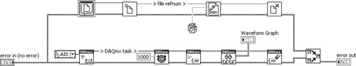
Figure 7-6B. DAQmx VIs and File I/O functions are interdependent. Sharing a common error chain facilitates error dependency and maximizes efficiency.
Rule 7.5
![]()
Trap all errors from all nodes that have error terminals
For best results, trap all errors returned from all nodes that have error terminals. This maximizes the application’s reliability. Some challenges and possible exceptions to this rule are explored in Section 7.3, “Prioritizing Errors.” However, I generally recommend trapping errors from all error terminals to the maximum extent possible.
7.1.2 Reporting Errors
When an error is trapped, report the error using a dialog or log file. The dialog is the simplest and most popular method of error reporting. It consists of a call to the Simple or General Error Handler VI. These VIs, located on the Dialog & User Interface palette, examine the error passed to their error in terminal, look up an error description from LabVIEW’s error code database, and generate a message describing the error. By default, they each open a dialog window that displays the error code, source, and description, which the user must acknowledge. An example is shown in Figure 7-7.
Figure 7-7. The Simple and General Error Handler VIs generate a dialog window that displays the error code, source, and description, which the user must acknowledge.
Rule 7.7
![]()
Use General Error Handler VI over Simple Error Handler VI
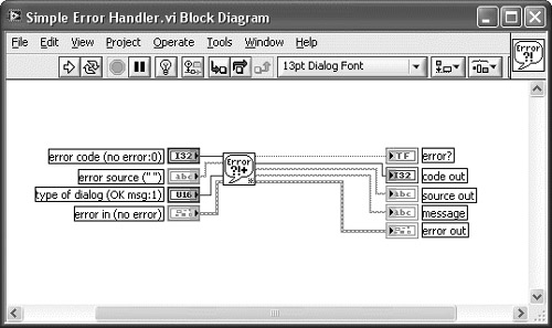
The General Error Handler VI provides the flexibility to handle user-defined errors and exceptions. The Simple Error Handler VI is nothing more than a call to the General Error Handler VI, with fewer input and output terminals exposed. The icon, terminal labels, and description for each are shown in the Context Help windows in Figure 7-8A. Curiously, Simple Error Handler VI is more prevalent throughout the LabVIEW shipping examples than General and appears to be the more popular choice. However, the Simple Error Handler VI is a trivial subVI that violates Rule 4.9. The diagram is shown in Figure 7-8B. Simply stated, it does not add enough value to warrant its existence. Instead, it reduces flexibility and adds unnecessary processing overhead. Each subVI layer entails a nominal amount of processing time, including the call to Simple Error Handler VI that contains General Error Handler VI. Therefore, the General Error Handler VI is the more flexible and efficient choice for dialog error reporting.
Figure 7-8A. The Simple and General Error Handler VIs are selected from the Dialog & User Interface palette. The primary difference is the number of terminals exposed.

Figure 7-8B. The diagram of the Simple Error Handler VI contains a call to the General Error Handler VI. This is a trivial subVI that violates Rule 4.9.
Rule 7.8
![]()
Implement an error log file for application deployment
After an application is deployed using the dialog error reporting method, it is often left up to the application’s users to relay information regarding errors to the developer. Without explicit instructions, users may acknowledge an error dialog without recording the error, or the information they record might be incomplete or not thoroughly communicated to the developer. Additionally, error dialogs may confuse or annoy many users. Consequently, an error log file is used in addition to or in place of the dialog error reporting method. The error log file method simply consists of a routine for programmatically logging error information to file.
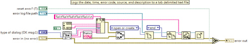
There are many possible methods of implementing an error log file routine. The primary considerations are readability and efficiency. For maximum readability, log a high-level error description, along with the code, source, date, and time, to a text file. This is shown in Figure 7-9A. The Get Date/Time String function, available from the Timing palette, is used to generate the date and time as ASCII character strings. The General Error Handler VI returns a message describing the error. The message output terminal is combined with the code, source, time, and date, and is written to a tab-delimited text file. The corresponding error log file can be read using any word processor or spreadsheet application. It is important to wire the type of dialog input terminal of the General Error Handler VI and to set the corresponding enumeration to no dialog if you want to suppress the dialog.
Figure 7-9A. The date and time are combined with the error message, source, and code, and are logged to a tab-delimited text file. Readability is maximized using this approach.
A second error log file method uses a datalog file format to optimize efficiency while sacrificing file readability. Specifically, bundle the error cluster with a time stamp and log the corresponding cluster to file, as shown in Figure 7-9B. The Get Date/Time in Seconds function, available from the Timing palette, returns the current time formatted using the time stamp data type. The datalog functions, including Open/Create/Replace Datalog, Write Datalog, and Read Datalog, are available from the File I/O»Datalog palette. The datalog file method saves the data in a highly efficient binary format, along with limited header information describing the data. This method is very simple to program. However, the data is not readable outside of LabVIEW. The datalog reading routine must consist of the Open/Create/Replace Datalog function with the cluster wired to the record type input terminal and the Read Datalog function. Use the datalog error log file if there is a possibility of many errors and efficiency is required, or if you want the file contents encrypted in binary format. However, text files are much more universal and are recommended otherwise.
Figure 7-9B. Efficiency is maximized while readability is sacrificed by logging the error data and time stamp to a datalog file. The resulting file is not readable without a LabVIEW datalog file reading routine.

An important consideration with error log files is parsing the errors into files. In some circumstances, such as error reporting within continuous loops that do not terminate on error, appending every error to one file could result in a large or runaway file. Large error log files are difficult to load using a spreadsheet or word processor application and may contain many redundant errors. Similarly, creating a new file for each new error prevents large files but may generate large quantities of files. As an alternative, consider an intelligent error logging routine that limits the size and number of errors saved to the error log file. Specifically, the error logging routine can read the contents of the error log file and either append to file, replace the oldest entry, or skip its logging operation. The number of logged errors, file size, or existence of redundant error codes can be used as criteria for appending, replacing, or skipping.
It is important to notify the user or developer when an error occurs. For best results, combine an error dialog or front panel indicator with a log file. The dialog or indicator notifies the user that an error occurred, and the log file contains a complete record of the error details. An error indicator may be a Boolean that indicates a new error was logged, or a numeric that counts the number of errors that have occurred, or simply an error cluster displaying the most recent error data. Alternatively, LabVIEW can send an email that includes the error log file as an attachment, using the VIs on the SMTP Email palette.
Rule 7.9
![]()
Suppress dialog error reporting for unattended or remote operation
The dialog reporting method, either with or without an error log file, is not practical for applications designed to run unattended or remotely. When a dialog opens and nobody is present to acknowledge it, the application may suspend itself indefinitely. Additionally, beware that LabVIEW’s web server cannot publish dialogs for remote clients accessing the application via web browser. In this case, the dialog will open on the server computer but is transparent to any remote clients. Avoid dialog error reporting in any of these situations.
It is important to carefully consider the placement of the error reporting routine. All error chains in an application must eventually terminate with a call to the error reporting VI. However, avoid calling the error reporting VI within continuous loops or within subVIs that might be called within continuous loops, unless corrective action is taken to gracefully recover from the error. Otherwise, the error reporting VI could cause the error dialog to repeatedly appear or the log file to grow very large. It is best to restrict the error reporting VIs to the top level, which helps consolidate error reporting and reduces the chances of reporting within a continuous loop. Additionally, it is helpful to merge all errors into one error reporting VI. The Merge Errors VI is a handy method of combining the errors from multiple error chains for reporting by a single VI.
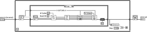
The Torque Hysteresis VI’s top-level diagram is shown in Figure 7-10. Observe that errors are trapped via propagation of the error cluster and are reported by the General Error Handler VI. If an error occurs the loop is terminated and the error is reported. The General Error Handler VI’s placement outside of the loop ensures that the dialog will appear only once, even if the loop’s termination logic changes. This example represents an extremely common error handling methodology applied to a simple application’s architecture.
Figure 7-10. The Torque Hysteresis VI traps errors via propagation of the error cluster, terminates the loop on error, and reports the error using General Error Handler VI. Notice that the General Error Handler VI is called only once.
Rule 7.10
![]()
Avoid subVIs with built-in error reporting
LabVIEW’s palettes contain several VIs that have error reporting built in. These VIs can be recognized on the palettes as high-level VIs, appearing in the top row of their subpalettes, that do not have error terminals. They include all VIs formerly known as the Easy I/O VIs, which are available from the traditional Data Acquisition subpalettes, and several of the high-level File I/O VIs. All such VIs are inflexible, providing only the dialog method of reporting errors. Additionally, the absence of the error terminals makes them more difficult to use in a dataflow sequence. Finally, these VIs are less efficient than the lower level VIs. Hence, I recommend avoiding them.
7.1.3 Error Codes
The error cluster contains a code control represented as a 32-bit signed integer. Codes are used to uniquely identify the errors that functions and VIs generate. LabVIEW maintains an internal database for which error codes are associated to descriptions. The categories and ranges of error codes, as of version 8.2 of LabVIEW, are shown in Table 7-1. This table relates the ranges of predefined error codes to the types of operations they are reserved for.
Table 7-1. LabVIEW Error Codes
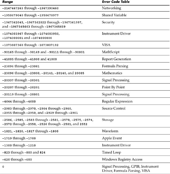
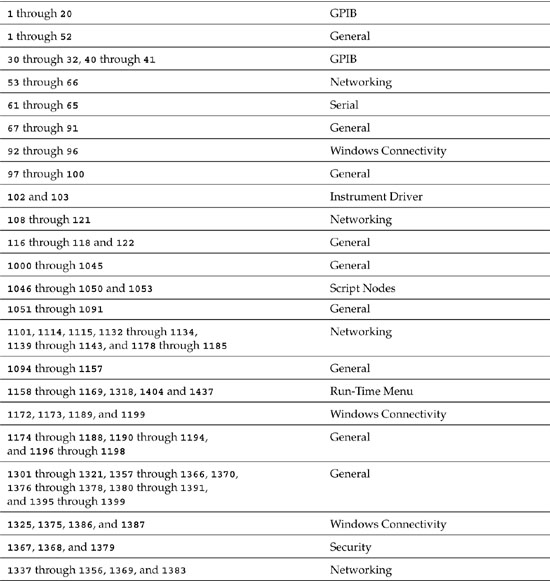
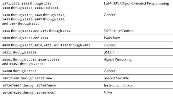
Additionally, LabVIEW reserves codes in the range of –8999 through –8000 and 5000 through 9999 for custom, user-defined errors. If your VIs need to flag a misbehavior that is not adequately described by one of the predefined error codes, define a new code in this range. The General Error Handler VI can be used to report user-defined errors. Simply specify the error codes and descriptions as arrays of integers and strings, and wire them to the associated terminals. This approach is very easy to implement if the application contains only one or a limited number of error reporting routines. However, it becomes more difficult if there are multiple instances of the General Error Handler VI, requiring multiple user-defined error codes. Specifically, the maintenance of the error codes and descriptions as arrays, along with propagating the data using wires, can be cumbersome.
Rule 7.11
![]()
Maintain user-defined error codes within an XML file
Instead, use an XML file to maintain multiple user-defined error codes and descriptions. Specifically, register custom error codes by creating an XML-based text file in the LabVIEWuser.liberrors folder. This is accomplished using the Error Code File Editor that is launched by selecting Tools»Advanced»Edit Error Codes. The user-defined error codes are registered within LabVIEW, similar to a predefined error. This has several advantages over the diagram definition method. First, you need not wire additional inputs to the General Error Handler VI. Second, the user-defined error codes may be used within any VI that runs under the instance of LabVIEW that contains the XML file. Finally, the Explain Error feature recognizes and explains errors defined in this manner. Explain Error is a built-in utility that displays information about an error code in a dialog. It is invoked by selecting Explain Error from the shortcut menu from any error cluster, or by selecting Help»Explain Error. When deploying applications, be sure to create an installer or source distribution that includes the XML file.
Rule 7.12
![]()
Use negative codes for I/O device errors, and positive codes for warnings
With I/O devices such as data acquisition hardware, positive codes are used to represent warnings that may not directly affect the application’s success, and negative codes represent significant errors that require corrective action or termination of the VI. As previously discussed, the error cluster’s status Boolean uniquely distinguishes an error. All nonzero codes are warnings if status = FALSE. However, it is good practice to follow the well-established sign convention for I/O devices.
7.2 SubVI Error Handling
Most LabVIEW functions and VIs with error in terminals evaluate the status Boolean and skip their code if the value is TRUE. This aids the application’s capability to recover from and report errors in a fast and efficient manner. For example, an I/O function such as VISA Read may wait 10 seconds for an instrument to respond to a query before returning a timeout error to the calling application. An error of this magnitude will likely degrade the application’s performance. If similar instrument queries execute with similar results, the application appears to be hung up or unstable. Trapping the error and propagating it to all subsequent nodes in the error chain prevents this from happening. Instead, all subsequent instrument queries that receive the error are skipped, thereby accelerating the propagation of the error to the reporting routine and aiding the application in a graceful recovery.
It is desirable for subVIs to mimic the error handling behavior of the LabVIEW functions and VIs. Specifically, most subVIs should skip their diagrams when an error is received at the error in terminal. This is implemented using an Error Case Structure, as follows: First, place the standard error in and error out clusters on the panel and assign them to the bottom left and right connector terminals, respectively. These standard connector assignments conform to Rule 5.26. Next, surround the completed subVI diagram with a Case structure and wire the error in cluster to the selector terminal. By default, the code will be contained by the No Error case. Use the Positioning tool to move the selector terminal near the bottom of the Case structure, and align the error in, case selector, and error out terminals vertically. Propagate the error cluster from the selector terminal to all nodes within the Case structure that have error terminals. Pass the error cluster through a tunnel on the right border to the error out indicator terminal. Inside the Case structure’s Error case, pass the error cluster data from the selector terminal straight through the output tunnel on the Case structure’s right border. The Error case is empty aside from the error cluster.
In the No Error case, you can also modify the error information, such as applying a user-defined error code and description if an error occurs. The error source can be provided by reading VI Server’s VI Name property, or reading and indexing the call chain returned by the Call Chain function. The latter function returns the entire hierarchy of callers, which helps pinpoint the specific instance of a subVI call that generates an error. The Case structure ensures that all of the subVI’s code will be skipped if an error is present. This maximizes the efficiency and responsiveness of your subVIs and the applications that call them.
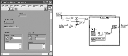
Figure 7-11 illustrates subVI error handling incorporated by DAQmx Read VI. In Figure 7-11A, the panel contains the standard error clusters assigned to the lower left and right connector terminals. Figure 7-11B shows the diagram including No Error and Error cases of an Error Case Structure. As shown, the No Error case primarily consists of a call to a Call Library node that performs the read operation, as well as a call to a utility VI named DAQmx Fill In Error Info VI. The Error case is empty except for the error cluster passthrough and a constant. Figure 7-11C shows the contents of DAQmx Fill In Error Info VI. This utility VI checks if a new error has occurred and creates the error source information using a combination of data returned from Call Chain and any message passed to extended error info. Because the error occurred in the subVI’s caller, the call chain is indexed by one element.
Figure 7-11A. The front panel of DAQmx Read VI contains the standard error clusters assigned to the lower left and right connector terminals.
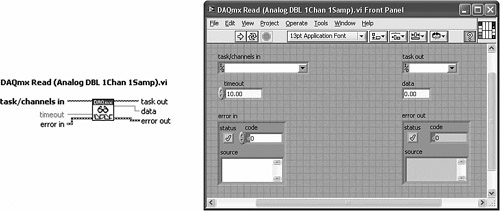
Figure 7-11B. The block diagram of DAQmx Read VI uses an Error Case Structure to skip its code if an error is present.
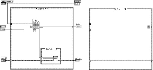
Figure 7-11C. DAQmx Fill In Error Info VI creates the error source information from a combination of data returned from the Call Chain function and any message passed to extended error info.
Rule 7.14
![]()
Use unwired defaults over constants for output tunnels of Error case
As a side note, the maintainability of DAQmx Read VI can be improved by using unwired defaults for output tunnels of the Error case instead of constants. Specifically, the numeric constant wired to the output tunnel leading to the data indicator terminal should be eliminated and replaced with the tunnel’s unwired default value. This is accomplished by selecting Use Default If Unwired from the tunnel’s shortcut menu. This provides several advantages over wired constants. First, indicators can be modified or deleted without requiring the developer to manually edit the constants and wires. Second, it is easier to confirm that the defaults are being used by simple inspection. Finally, the diagram appears cleaner without the constants. Wire constants to output tunnels only if the value is not the data type’s default.
Prior to LabVIEW version 8.2, the Call Library Node did not have error terminals. Consequently, the Case structure was the only method of preventing a dynamic link library function call from executing. Error Case Structures are also used to increase the efficiency within subVIs containing functions that do propagate the error cluster. If your subVI is an instrument driver, for example, propagating the error cluster among VISA functions ensures that an error upstream will prevent VISA functions downstream from executing. However, most instrument drivers perform substantial command string manipulation and response parsing, in addition to the instrument communications. Processing efficiency is optimized by enclosing these functions within the Case structure as well.
In Figure 7-12A, an instrument driver subVI for a digital multimeter assembles a command using several string manipulation functions and sends the command to the instrument using a call to VISA Write. This subVI contains incomplete error trapping. Specifically, the error cluster is passed to the VISA Write function only. The error terminals on three Format Into String functions are unwired. Consequently, these functions execute regardless of the error status of the error in cluster. In Figure 7-12B, an Error Case Structure encloses all the subVI’s code, and the error cluster is shared among all nodes that have error terminals. Additionally, functions that do not have error terminals, such as In Range and Coerce, Select, and Pick Line are now enclosed by the Error Case Structure and will not execute if an error is present. Because of the lack of error terminals, the Case structure is the only method that prevents these functions from executing. Hence, the Error Case Structure maximizes efficiency in the event of an error. Additionally, notice that the diagram nodes have been horizontally aligned about an axis defined by the error terminals.
Figure 7-12A. An instrument driver subVI contains incomplete error trapping and inefficient recovery when an error is received.
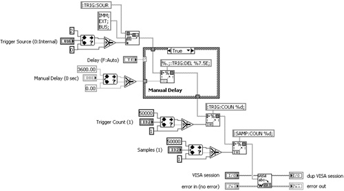
Figure 7-12B. The error cluster is shared among all functions that have error terminals, and an Error Case Structure maximizes efficiency in the event of an upstream error.
LabVIEW functions and subVIs that do not skip their code on error include most nodes that terminate a session to a resource. This includes Close Reference, VISA Close, Close File, and several nodes that have Destroy, Stop, Close, and Clear in their name. SubVIs that call these nodes should not skip them on error. Instead, confirm their behavior by carefully reading the error in terminal description in the node’s detailed help or inspecting its diagram. If the description indicates the node runs normally if an error occurs before it, the node should be placed outside the subVI’s Error Case Structure. As an example, all LabVIEW Plug and Play instrument drivers include a Close VI that calls the VISA Close function. These subVIs do not contain an Error Case Structure.
Rule 7.15
![]()
Use the SubVI with Error Handling template
If you like shortcuts, begin your subVIs with the SubVI with Error Handling template, selected from New»VI»From Template»Frameworks»SubVI with Error Handling. This template initiates a new VI that contains the error handling mechanisms for a subVI described in this section. This template saves a minute or two on each subVI and helps ensure consistent quality throughout your applications.
7.3 Prioritizing Errors
Per Rule 7.5, it is best to trap all errors returned from all nodes that have error terminals. This helps maximize the application’s reliability. In practice, however, I know of few developers who rigorously wire the error terminals on every node of every diagram. In fact, there is a potential conflict between Rule 7.5 and some of the wiring rules in Section 4.2. In a dense diagram that contains parallel dataflow paths, wiring every error terminal may lead to overlapping wires, excessively large diagrams, or right-to-left data flow. Finding the best layout that optimizes these diverse requirements may become time consuming. What tradeoffs are permissible in the interest of saving time while maintaining reliability and good style? To answer this question, consider your understanding and comfort level of each node’s operation, the importance of the operation’s success within your application, and your tolerance for risk.
If you are like me and you learned to use the Visible property for a front panel control back in version 3.0 of LabVIEW, previously packaged as an Attribute Node that did not have error terminals, you might be able to justify skipping the error trapping on this one. However, beware that there have been some subtle changes in the behavior of various functions and properties from one version of LabVIEW to the next. The Synchronization and Communication functions, for example, seem to incorporate new enhancements with each new release. Error handling helps us identify and learn about the differences between versions and port our applications more reliably.
LabVIEW’s functions and VIs can be categorized in terms of risk, to help understand the types of errors they generate and evaluate handling strategies with respect to a given application. The probability and severity of an error depends on the application and the system. However, different types of operations have different levels of risk of generating errors and different types of associated misbehavior, regardless of the application or platform. Specifically, I find it useful to categorize the nodes on the palettes in three levels of risk: high, medium, and low. Then prioritize the error trapping based on the perceived risk.
LabVIEW’s error out terminal is the primary method by which LabVIEW errors are returned from nodes that generate errors. An exception includes nodes that return an error code as a scalar integer, such as the Mathematics VIs and many Call Library Function Nodes developed prior to LabVIEW version 8.2. The presence or absence of the error out or error code terminal in a node’s connector pane is one indicator of the risk associated with that node. The basic mathematics functions available on the Numeric palette, for example, do not have error terminals and do not return errors. This is because LabVIEW gracefully handles all combinations of problems that may arise, and misbehavior is almost impossible. Division by zero, for example, returns the value Inf, which is a valid constant understood by all of LabVIEW’s numeric functions, controls, and indicators. Therefore, simple mathematics functions do not require error handling. Likewise, all functions on the remaining palettes that do not contain error terminals do not generate errors. This includes many functions available from the Structures, Array, Cluster &Variant, Boolean, String, Comparison, and Timing palettes, as well as many other palettes.
At the opposite end of the risk spectrum are functions and VIs that perform input and output (I/O) operations. These nodes make calls to device drivers, DLLs or shared libraries, the operating system, or any application or resource that is external to the LabVIEW environment, including remote instances of LabVIEW. I/O operations include all of the nodes available on the following palettes: File I/O, Measurements I/O, Instrument I/O, and Data Communication. These nodes are risky because they rely on an external driver or a resource that may or may not be in a state that will respond appropriately to an application’s requests. The external resources perform their I/O operations independent of LabVIEW, and there are many scenarios in which the operation could fail. Also, failed I/O operations are more likely to cause the calling application to misbehave, such as hang up waiting for a device to respond. Most I/O functions and VIs in LabVIEW return the error cluster. Trapping and handling the returned error information is an absolute necessity!
Medium-risk nodes have error terminals but are not calling resources external to the LabVIEW environment. These include Property Nodes associated with front panel controls, all functions in the Synchronization palette, VI Server when controlling the local instance of LabVIEW, most Express VIs (with the exception of the VIs on the Express Input and Output subpalettes), Scan from String and Format into String, and Mathematics VIs. Most of the errors generated by medium-risk nodes are well behaved and will not cause long latencies or crashes. Error handling is the best method of identifying problems with how these functions are being applied and is strongly recommended. For example, wiring the error returned from a Property Node helps determine that a programmed property value is invalid, which may otherwise go unnoticed.
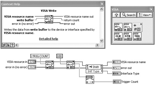
Figure 7-13 provides source code samples for functions in the three categories of risk. Figure 7-13A contains a mathematical operation using numeric functions that do not have error terminals. None of the functions on the Numeric palette contain error terminals, and they have no risk of misbehaving. Figure 7-13B contains a Property Node and Scan from String function, with error terminals wired. These functions have medium level of risk, and error handling is recommended. Figure 7-13C contains VISAWrite and Read functions, which are examples of high-risk I/O functions. Error handling is essential for I/O operations, including instrument communications with VISA.
Figure 7-13A. The functions on the Numeric palette do not have error terminals, cannot generate errors, and do not misbehave. These functions are categorized as low risk.
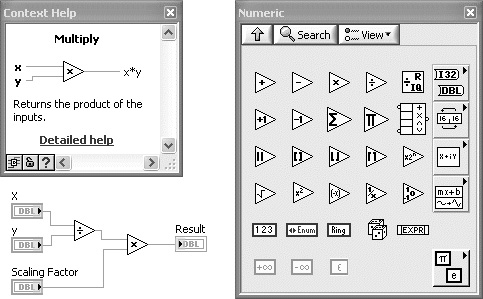
Figure 7-13B. Property Nodes associated with front panel controls and the Scan from String function are examples of medium risk nodes. Errors are usually not fatal, but error trapping is highly recommended.
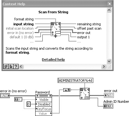
Figure 7-13C. Functions that call external device drivers such as VISA have a high level of risk of generating an error, and the corresponding errors are often detrimental to the calling application. Error handling is essential with I/O functions.
Rule 7.16
![]()
Error trapping is required for nodes that perform I/O operations, recommended for nodes that contain error terminals, and optional for diagrams that do not contain nodes with error terminals
Trap all errors from all nodes that have error terminals, to the maximum extent possible. However, when style conflicts arise, prioritize error trapping according to the three classes of nodes just presented. A firm, minimum requirement is to positively handle any errors generated by nodes that perform I/O. As discussed, I/O functions and subVIs have a higher risk of generating errors and greater consequences when errors happen. Additionally, error trapping is highly recommended for the medium-risk nodes that have error terminals but do not perform I/O. Errors returned from these nodes help the developer understand how they work and help ensure reliable applications. Finally, when creating routines that contain nodes without error terminals, error propagation via Error Case Structure or subVI with error terminals is optional. In the latter case, propagating the error cluster to the subVI is useful for data flow, maintains standard connector terminal patterns and assignments, and optimizes error reporting and recovery.
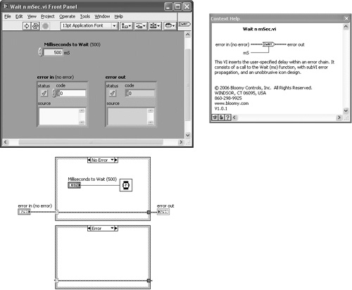
Figure 7-14A contains the front panel, block diagram, and Context Help window for Wait n mSec VI. This subVI simply inserts a delay within an error chain. The unique icon shape and connector pattern are discussed in Chapter 5, “Icon and Connector.” The diagram contains the Wait (ms) function and proper subVI error handling. Note that the Wait (ms) function does not have error terminals and cannot generate an error. It is an example of a low-risk function. However, the subVI incorporates error propagation and an Error Case Structure for skipping the code on error, per the rules in Section 7.2. Moreover, the subVI’s error terminals allow the calling VIs to use data dependency to specify when the delay occurs, and to skip the delay if an error is already present.
Figure 7-14A. Wait n mSec VI consists of the Wait (ms) function, a low-risk function without error terminals, and proper subVI error handling, including the Error Case Structure.
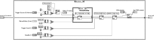
In Figure 7-14B, the Wait n mSec VI is applied to an instrument communications example. Specifically, the Wait n mSec VI is inserted between VISA Write and a Property Node that returns the Number of Bytes at Serial Port. This delay gives the instrument time to respond to the query before reading the response. Note that any errors returned prior to the Wait n mSec VI cause the delay to skip. Therefore, error handling with this subVI facilitates execution ordering via data dependency and optimizes the efficiency in the event of an error.
Figure 7-14B. Wait n mSec VI inserts a 100ms delay between the VISA Write function and a Property Node, allowing an instrument time to respond to a query.

7.4 Error Handling Tips
This section provides tips on error handling, including structure wiring, merging errors, clearing errors, and automatic error handling.
7.4.1 Structure Wiring
Rule 7.17
![]()
Tunnel the error cluster near the bottom of structures
Wire the error cluster through structures, including loops, Case, Event, and Sequence, via vertically aligned input and output tunnels on the left and right borders. Each structure should have only one error input and output tunnel pair, and they should normally be the bottom-most tunnels. All the examples in this chapter support this convention. However, do not wire the error cluster through a multiframe structure if it is not used within the structure.
7.4.2 Merging Errors
Merge Errors VI was introduced in Section 7.1.1, “Trapping Errors,” as a method for combining multiple error clusters into one. As shown in the Context Help window of Figure 7-15A, it has three error in terminals, one error in array terminal, and one error out terminal. The VI searches the error inputs in top to bottom terminal order and returns the first error it finds. If no errors are found, it returns either the first warning or no error if there are no warnings. This technique is used for combining multiple parallel error chains, such as in Figure 7-3, or converting an array of loop indexed errors into a scalar, as shown in Figure 7-5A. The merged error output cluster facilitates error propagation using a single error out terminal or reporting using a single reporting VI.
Figure 7-15A. Five parallel error chains are combined using Merge Errors VI. Because of the nonstandard error in array terminal at the bottom left, the subVI is not aligned with any of the other subVIs. Also, a Build Array function is required to merge five error chains.
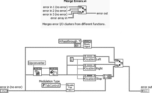
Merge Errors VI violates connector Rule 5.25, “Assign error clusters to bottom left and right terminals,” by replacing the error in cluster that is normally assigned to the bottom left terminal, with the error in array. This causes a misalignment of the icon and terminals when Merge Errors VI is used with scalar error chains, as shown in Figure 7-3. Likewise, misalignments occur with loop indexed arrays of errors in parallel with reference numbers, as shown in Figure 7-5A. Moreover, the error in array terminal has limited value. Arrays of error clusters are formed by indexing errors on loop tunnels or building an array that combines multiple error clusters. As discussed in Section 7.1.1, “Trapping Errors,” indexing errors is not recommended. Instead, most loops check the error status and terminate on error, or propagate a scalar error cluster using a shift register. Also, the Merge Errors VI’s merging operation defeats the purpose of forming the array, if one existed.
Figure 7-15B presents Merge Multiple Errors VI1, an alternative to Merge Errors VI, containing five additional error in terminals and no error in array terminal. It uses the standard 4×2×2×4 connector pattern, with all left and middle terminals assigned to error in clusters. Hence, it merges up to eight scalar error in clusters into one scalar error out cluster. This increases the number of error chains that can be merged, while promoting good error handling, wiring, and connector style.
Figure 7-15B. Merge Multiple Errors VI combines up to eight scalar error in clusters using the standard 4×2×2×4 connector pattern. The subVI is vertically aligned with the error terminals and other subVIs.
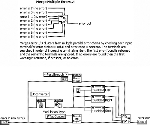
In Figure 7-15A, five parallel error chains are combined using the Merge Errors VI. The Build Array function is required to combine two of the error clusters into an array, and the subVI is positioned approximately near the middle of the pack of parallel error chains. In Figure 7-15B, the Merge Multiple Errors VI is used to combine all error chains. Because the lower left terminal conforms to Rule 5.26, this subVI is vertically aligned with the error terminals and subVI of the bottom error chain. Also, the Build Array function is eliminated, and the diagram contains fewer wire bends. Finally, a middle connector terminal is utilized to merge five error chains in this example.
7.4.3 Clearing Errors
Error handling identifies two classes of misbehavior: errors and warnings. Errors are uniquely distinguished by a TRUE value of the error cluster’s status Boolean. Warnings correspond to any nonzero codes accompanying a FALSE error status. As discussed, when an error is trapped within an error chain, most nodes upstream from the error skip their code. The exceptions include most functions that close a reference, such as File Close, VISA Close, Close Reference, and Release Queue. In some situations, it is desirable to either downgrade or ignore specific errors so that upstream nodes execute normally.
As an example, consider a communications server application in which client connect and disconnect operations are routine tasks. The communications functions return an error when the client disconnects. The server program needs this information to clear its connection with the client and begin looking for new client connections. However, if the disconnect error is propagated throughout the server application, the communications functions will not execute, and any new client connection attempts will be thwarted. Instead, the server should process and clear the error associated with a client disconnect.
Figure 7-16 illustrates a utility subVI named Clear Error All or Specified VI1. Its purpose is to programmatically reset the error cluster with no error when the error in cluster’s error code contains the programmed value of Code to Clear. Alternatively, the VI resets all errors or warnings if the Code to Clear terminal is unwired or 0. Also, it can optionally display the error dialog before clearing the error. Notice the small icon size. This allows other wires on the calling VI’s diagram to flow above the subVI without the icon obstructing their path. For example, any reference numbers running in parallel to the error cluster can pass without bending around the icon. The icon and connector for Clear Error All or Specified VI are discussed in Chapter 5.
Figure 7-16. Clear Error All or Specified VI is a utility that selectively clears errors and warnings according to the value of Code to Clear.

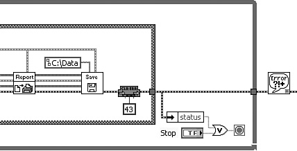
Figure 7-17 contains an illustration of Clear Error All or Specified VI applied to the Torque Hysteresis VI discussed in Chapter 6, “Data Structures.” After each test, Save Data VI prompts the operator for a filename using a file dialog, and the test data is logged to file. However, if the user cancels out of the file dialog, the VI returns error code 43. This error causes the loop to terminate unless it is cleared from the error cluster before checking the error status. Consequently, Clear Error All or Specified VI is used to clear error code 43 and continue the application.
Figure 7-17. Clear Errors All or Specified VI clears error code 43 from Torque Hysteresis VI. This error naturally occurs when the user cancels a file dialog.
7.4.4 Automatic Error Handling
Automatic error handling is an alternate method for trapping errors that is transparent to the diagram. It consists of a VI property named Enable automatic error handling, selected from the Execution category of the VI Properties dialog. When an error occurs in any node with the error out terminal not wired, LabVIEW suspends execution, opens the diagram window, highlights the node, and displays an error dialog. If the node’s error out terminal is wired, the error data propagates as programmed and no additional action is performed. Automatic error handling is disabled by default in all versions of LabVIEW except for 7.0, the version in which the feature was initially released.
It is important to note that automatic error handling does not ensure that errors are reported. If a node’s error out terminal is wired but the error cluster terminates without a reporting routine, the error data is lost. Hence, automatic error handling helps only when one or more node’s error out terminals are unwired, such as when nodes have been prioritized by risk, as discussed in the previous section. However, most error handling problems I have seen in practice are the result of incomplete error handling, in which many of the error terminals are wired but the error is not fully trapped or reported. Automatic error handling does not help in these situations.
Rule 7.18
![]()
Leave automatic error handling disabled
If you are deploying an industrial application, the last thing you want is the application to suspend itself, open the diagram, and highlight a portion of the source code. This invites anyone who happens to be in front of the computer when the error occurs to tinker with the diagram. Hence, automatic error handling must be disabled before application deployment. Additionally, note that automatic error handling circumvents programmatic error handling. Per Theorem 7.1, programmatic error handling is essential for overcoming unforeseen problems before, during, and after deployment. Moreover, programmatic error handling is a principle method of establishing data flow and a key ingredient to good style. Therefore, use programmatic trapping and reporting of errors, and leave automatic error handling disabled.
7.5 Examples
This section contains more error handling examples, including loops, user-defined error, parallel error chains, and a state machine.
7.5.1 Continuous Acquire To File
Cont Acq&Graph Voltage-To File(Binary) VI is a shipping LabVIEW example that continuously acquires data and logs it to file using the DAQmx VIs and File I/O functions. The DAQmx VIs share a common task, and the File I/O functions share a common reference number and are placed in parallel to facilitate propagation of these data elements. Because the nodes are interdependent, a common error chain is shared between the VIs for error dependency and execution ordering. The loop terminates if an error occurs in any node, and an error message is reported with a dialog. The implementation shown in Figure 7-18A is located using NI Example Finder, as follows: Hardware Input and Output»DAQmx»Analog Measurements»Voltage»Cont Acq&Graph Voltage-To File(Binary) VI.
Figure 7-18A. The shipping example continuously acquires data and logs it to file. The error cluster is shared by the DAQmx VIs and File I/O functions because the nodes are interdependent. The loop terminates if an error occurs in any node, and it is reported in a dialog.
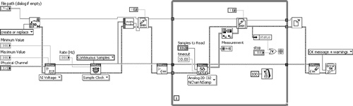
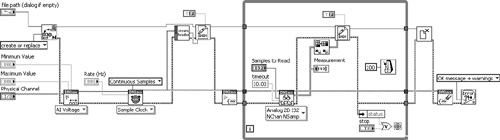
Figure 7-18B contains a few minor enhancements from the shipping example. First, the error cluster enters and exits the While Loop through vertically aligned tunnels located near the bottom of the loop. Additionally, the loop condition is placed in the bottom right corner of the loop, along with the code that unbundles the error status and evaluates the loop condition. Finally, the General Error Handler VI is used instead of the Simple Error Handler VI.
Figure 7-18B. Minor improvements to the shipping example include vertically aligned error tunnels at the bottom of the loop, loop condition at the bottom right, and General Error Handler VI.
7.5.2 Suss Interface Toolkit
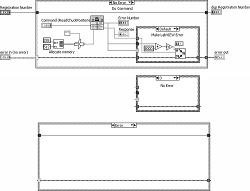
Figure 7-19 contains the diagram of an instrument driver VI that controls a semiconductor wafer probe system. The diagram incorporates subVI error handling that includes error cluster terminals and an Error Case Structure. The No Error case of the Error Case Structure executes the Call Library Node and an error routine. The Call Library Function Node calls a function that resides within a dynamic link library (DLL). The function returns a parameter with integer data type named Error Number. This parameter returns a value of 0 if the function succeeds, or an integer in the range of 500 to 600 identifying any errors that occur within the DLL. The error routine evaluates the Error Number and generates an error cluster using Error Cluster from Error Code VI. The resulting LabVIEW error consists of a code that is derived from the original Error Number returned from the DLL but shifted into the range of LabVIEW user-defined errors (–8999 to –8000, 5000 to 9999). Specifically, an Error Number from 500 to 600 is shifted to an error code from –8500 to –8600. Per Rule 7.12, negative error codes are preferred for I/O device errors. Also, the error cluster’s source is populated with an intuitive message consisting of the call chain and the response returned from the DLL.
Figure 7-19. Instrument driver subVI uses a Call Library Function Node to call a function in a DLL. If an error is returned by the DLL, the Error Number is shifted into the range of user-defined errors.
7.5.3 Merge Parallel Errors
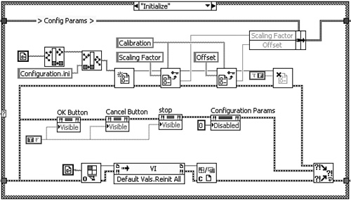
Figure 7-20 illustrates an initialization routine that reads configuration parameters from file using Config VIs, sets several control properties using Property Nodes, and initializes all control values to default using VI Server. These nodes form three parallel error chains that are merged prior to exiting the Case structure through an output tunnel. Merge Errors VI has a nonstandard error in array assigned to the lower left terminal. This causes a kink in the error cluster wire passed from the VI Server Close Reference function, as shown in Figure 7-20A. In Figure 7-20B, Merge Multiple Errors VI contains only scalar error terminals, including the bottom left terminal that is normally reserved for the error in terminal. This subVI eliminates the wire kink and promotes standard error terminal assignments.
Figure 7-20A. Merge Errors VI has a nonstandard error in array terminal that causes a wire kink when used to merge parallel error clusters.

Figure 7-20B. Merge Multiple Errors VI has eight scalar error in terminals, which eliminates wire kinks and promotes good style.
7.5.4 Screw Inspection VI
Screw Inspection VI is an image processing application that was previously discussed in Chapter 4. The diagram snippet shown in Figure 7-21A contains two incomplete parallel error chains within a For Loop. The top error chain consists of three overlay VIs from the Vision Utilities palette. Mysteriously, the rightmost VI is omitted from the error chain. Also, the error is propagated among the Find Screw Ends VIs in the bottom error chain, but the first VI’s error in terminal and the last VI’s error out terminal are unwired. Hence, the error is not trapped in either error chain. Additionally, the Case structure containing the Wait (ms) function has no data dependency with the remaining nodes, and the order in which the delay occurs is not known.
Figure 7-21A. Screw Inspection VI contains two incomplete parallel error chains within a For Loop, and a Wait (ms) function with unknown execution order.
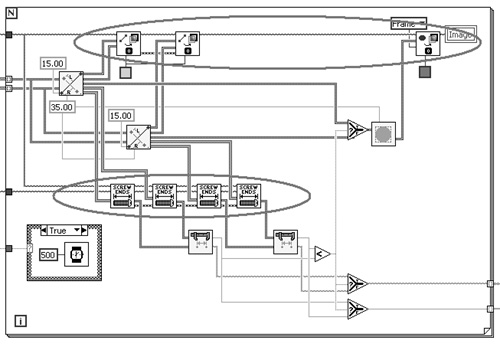
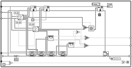
Figure 7-21B illustrates proper error trapping for parallel error chains and For Loops. First, the error cluster is propagated to the error in terminal of all nodes that have error terminals. Second, the error out terminal of the last node in each chain is wired to the Merge Multiple Errors VI. Error propagation between For Loop iterations is accomplished using a shift register. Finally, the Wait n mSec VI replaces the Wait (ms) function and Case structure. This VI’s error terminals facilitate execution ordering via natural data flow, and the icon’s unique size and shape allow easy insertion within an error chain. The delay now reliably occurs at the beginning of the bottom error chain, before the four Find Screw Ends VIs. Figure 7-21C is similar to Figure 7-21B, except that a While Loop replaces the For Loop and a few nodes are rearranged. The While Loop allows the loop to terminate if an error occurs in any loop iteration. Nodes are rearranged so that the error cluster is the bottom-most output tunnel. Anew input tunnel is required to specify the desired number of loop iterations. The input tunnel is located below the error cluster input tunnel, to pass it to the expression that evaluates the stop condition without crossing other wires and objects. Hence, Rule 7.17 has been sacrificed in favor of Rule 4.15.
Figure 7-21B. Error trapping is completed by extending the error cluster to all error terminals, merging parallel error chains, and passing the error cluster between loop iterations using a shift register. The Wait n mSec VI uses data flow to order its delay before the Find Screw Ends VIs.

Figure 7-21C. A While Loop is used to terminate the loop on first error. Nodes are rearranged to eliminate output tunnels below the error cluster.
7.5.5 Test Executive VI
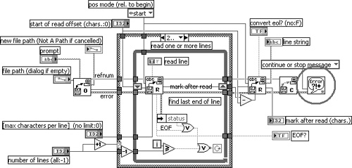
The application in Figure 7-22 is a test executive implemented using a variation of a state machine design pattern discussed in Chapter 8, “Design Patterns.” Two cases of the primary Case structure, Initialize and Load Script, are shown. In the Initialize case, the error terminals are unwired on all nodes, including two variables, nine Property Nodes, and a File Dialog Express VI. Also, a high-level VI is used for reading the test steps from file that has error handling built in. Specifically, Read Lines from File VI contains a call to the General Error Handler VI with the type of dialog input set to continue or stop message. This is shown in Figure 7-23. An error passed to this subVI generates a dialog, which may not be desirable if the test executive is intended to run unattended.
Figure 7-22. The Initialize and Load Script cases of a test executive are shown. The Initialize case has many nodes with unwired error terminals. The Load Script case propagates the error cluster between subVIs, but the error out terminal of the last subVI in the error chain is unwired, allowing the error to disappear.

Figure 7-23. The diagram of Read Lines from File VI includes error handling via the General Error Handler VI. The error dialog is not desirable for unattended operation.
The Load Script case contains a sequence of subVIs that interact with a spreadsheet application. The error cluster propagates among all subVIs, but the error is not trapped or reported. The last subVI in the error chain’s error out terminal is not wired, allowing the error data to disappear. Likewise, the error handling throughout the remaining cases is incomplete. This is evident at a glance because the error cluster does not enter or exit the Case structure or While Loop. Incomplete error trapping combined with no error reporting equates to nonexistent error handling.
In Figure 7-24, Test Executive VI has been modified with proper error handling. First, the error cluster is read from the error in control terminal and initializes a shift register near the bottom of the While Loop. The error is read from the shift register and passes through a tunnel near the bottom of the Case structure. Each case of the Case structure, including Initialize and Load Script, propagates the error cluster among all nodes that have error terminals and returns the error cluster through the tunnel at the bottom right of the Case structure. Therefore, an error generated by any node in any case is trapped inside the error chain. Outside the Case structure, the error cluster’s status is unbundled, and if an error exists, the Error is passed into the shift register on the right border and the Error case executes next. The Error case logs the error and time stamp to a datalog file, and clears the error from the error cluster.
Figure 7-24. The test executive has been modified to implement proper error handling. Errors are trapped by propagating the error cluster to all nodes that have error terminals, and are reported by logging to a datalog file in the Error case.

Notice that the Initialize case now contains the intermediate level File I/O functions in place of Read Lines from File VI. This allows the error cluster to propagate in a manner that is consistent with the rest of the application and to avoid any dialogs from popping up during unattended operation. Finally, note that the error in control and error out indicator are not required in this example because it is a top-level VI. However, it is a good practice to write all VIs assuming that they might be used as a subVI and may require propagating the error cluster. For a GUI VI, the error clusters can be placed outside the visible area of the panel.
Endnotes
1 Merge Multiple Errors VI and Clear Error All or Specified VI can be downloaded from www.bloomy.com/lvstyle.