
Chapter 2
Minimal Energy and Stability Rubrics
2.1 Abstract
This chapter describes basic themes of stability for liquids in contact with various geometries of walls. A few simple rules can lead to a well-developed intuition of the stability of liquid shapes in general circumstances. There are some configurations for which it is possible to prove mathematically what the absolute minimum energy shapes are. Obviously, minimum energy shapes are stable.
A brief summary of the rubrics (very loosely stated):
- Spherical drops are usually minimal energy.
- Rotational symmetry means lower energy.
- Pressure increasing with volume means stability.
- Pressure decreasing with volume can give rise to a “double-bubble” instability.
The first section focuses on spheres, and works through a gallery of examples where a spherical section is the minimum energy surface. Included are droplets on planes, droplets in wedges, bridges between parallel planes, and droplets outside convex bodies. It is also possible to include configurations with mobile walls. The second section describes how “symmetrization” to rotational symmetry lowers the energy. This leads to the classic rotationally symmetric surfaces of constant mean curvature: the sphere, the cylinder, the catenoid, the unduloid, and the nodoid. Sections of these surfaces often turn up as bridges between parallel substrates. The third section describes a general method of showing stability in cases where the pressure increases as volume increases. This applies, for example, to concave liquid shapes in corners and grooves. The fourth section discusses the “double-bubble” instability, which arises when pressure decreases with volume, and there are separate parts of the liquid that can somewhat independently grow and shrink. The famous Plateau-Rayleigh instability of a liquid cylinder may be seen as an example. The last section contains a more precise summary of the rubrics.
The basic formulations of the rubrics omit gravity, but some of them do apply when gravity is present; that will be noted in the sections below. Otherwise, for microdrops gravity can be imagined as making small corrections.
The common geometric properties of the surfaces in this chapter are first, constant mean curvature (due to constant pressure, since gravity is not being included), and second, constant contact angle at any boundary wall (although the angle may vary on different walls). In two dimensions, that means that all interface; curves are arcs of circles, which makes it possible to prove minimal energy configurations by enumerating all possible geometries of circular arcs. But we cannot take that approach in three dimensions, since constant mean curvature surfaces need not be sections of spheres.
This chapter contains a few mathematical proofs at the level of multivariable calculus. They are included because they are so short and wondrous. For those who worry that calculus only applies to smooth surfaces and we are not assumming that here, rest assured that the mathematical field known as Geometric Measure Theory [1][2] makes it possible to apply all the standard concepts of multivariable calculus to arbitrary geometrical shapes, no matter how rough or nondifferentiable.
2.2 Spherical Shapes as Energy Minimizers
2.2.1 The Sphere Theorems
It is well-known that a sphere is the least- area surface that can enclose a given volume. Spherical shapes turn up a lot in contact-angle problems because a sphere has the nice property that its intersection with a given plane has a constant contact angle, which depends only on the distance of the plane from the center of the sphere and not on the orientation of the plane.
A proof of area-minimality due to Gromov [3] can be generalized to cover the case where there are walls with given contact angles. Gravity is assumed to be absent, so the total energy of the system is the free surface area plus the wall contact energy. Basically, the theorem says that if a spherical drop happens to hit the walls of a convex region with exactly the right contact angles, then the spherical drop minimizes the total energy.
Theorem 2.1. Suppose Ω is a polyhedral convex region (possible infinite, possibly even all of space) defined by boundary planes Ti, with each plane Ti having a prescribed contact surface tension γi. For any region U of Ω, define the energy E(U) of U to be the sum of the area of the free surface of U, ∂U0 = ∂U ∩ interior(Ω), and the sum of the areas of U intersecting the boundary planes Ti, each multiplied by the appropriate tension γi:
(2.1) ![]()
Suppose S is a sphere such that the angle of intersection of S with each boundary plane Ti satisfies Young’s Law, assuming the free surface of the sphere has surface tension 1, and if S does not intersect Ti then γi ≥ 1. Suppose W is the intersection of a sphere S with Ω. Then the energy of W is least among all regions U of Ω with equal volume, and any region of equal energy must be a translation of W.
Proof. The theorem is true in any ambient dimension, but we will state the proof in three dimensions for simplicity. We may assume the center of the sphere S is at the origin. We may further assume the radius of S is one. Let the boundary ∂W of W be made up of a free surface ∂W0 and a set of plane pieces ∂Wi = ∂W ∩ Ti. Then the energy of of W is equal to 3 times its volume:
(2.2) ![]()
(2.3) ![]()
(2.4) ![]()
(2.5) ![]()
(2.6) ![]()
(2.7) ![]()
Here ![]() is the unit normal vector,
is the unit normal vector, ![]() is simply the position vector
is simply the position vector ![]() , and
, and ![]() is exactly the sphere intersection assumption.
is exactly the sphere intersection assumption.
Now we prove any competitor region U of the same volume has equal or greater energy. Let a volume-preserving map ![]() W be defined by
W be defined by ![]() (x, y, z) = (f1(x), f2(x, y), f3(x, y, z)), with each component map monotone increasing in its last variable. This map can be constructed dimension by dimension, with f1(x) defined first so the volume in W of x ≤ x0 is the same as the volume of x ≤ f1 (x0), then defining f2(x, y) with area on each x slice, etc. This makes the Jacobian matrix of f triangular, so the Jacobian determinant is the product of the main diagonal. Thus by volume conservation,
(x, y, z) = (f1(x), f2(x, y), f3(x, y, z)), with each component map monotone increasing in its last variable. This map can be constructed dimension by dimension, with f1(x) defined first so the volume in W of x ≤ x0 is the same as the volume of x ≤ f1 (x0), then defining f2(x, y) with area on each x slice, etc. This makes the Jacobian matrix of f triangular, so the Jacobian determinant is the product of the main diagonal. Thus by volume conservation,
(2.8) ![]()
and hence by a standard mathematical inequality
with equality if and only if all the partials concerned are 1. Then

Uniqueness up to translation follows from tracing the conditions of equality. Equality in equation (2.9) requires the diagonal elements of the Jacobian to be 1, and equality in equation (2.10) then requires the off-diagonal elements of the Jacobian to be zero on the boundary. Hence the Jacobian is the identity matrix around the boundary (and inside, it can be shown), so the regions are identical except possibly for translation.
The theorem as stated here skips over a lot of technical niceties, such as the definitions of “area” and “boundary” and divergence of a nonsmooth vectorfield, but these can be handled with geometric measure theory as mentioned earlier, and it turns out that everything works just like it does for nice smooth surfaces and vectorfields.
Theorem 2.1 can be generalized to compare energies of regions in two different convex domains, if the second domain Φ has contact angles depending on wall orientation the same as domain Ω. That is, the walls of Φ are parallel to the walls of Ω, with the same contact angles.
Theorem 2.2. Suppose Ω and W are as in Theorem 2.1. Suppose Φ is a convex polyhedral domain such that the contact surface tension on each boundary plane Φ is the same as on a parallel boundary plane of Ω. Then the energy of W is less than or equal to any region of Φ with equal volume, with equality only if U is a translation of W.
Proof. The proof is the same as for Theorem 2.1, which really didn’t use the fact that the competitor region U was in the same domain.
One application of Theorem 2.2 is that if a boundary plane is mobile (for example, a chip floating on a solder drop), then the solder drop will push or pull on the chip to make a spherical drop.
2.2.2 Sphere
The simplest application of Theorem 2.1 is the case where the convex region Ω is the whole space and W is a complete sphere. There is no boundary of Ω, so no contact angles, and the theorem simply says the sphere is the least area surface enclosing a given volume.
2.2.3 Spherical Cap on a Plane
The next simplest case is when the convex region Ω is a half-space bounded by a single plane with a constant contact angle. Then Theorem 2.1 says the minimum energy drop is a spherical cap with the center of the sphere located to make the intersection of the sphere and plane happen at the given contact angle, as shown in figure 2.1.
Figure 2.1 (a) Hydrophobic drop as section of sphere. (b) Hydrophilic drop as section of sphere.

2.2.4 Drop Between Parallel Plates
A droplet of liquid between two parallel plates has least energy when it has a spherical shape, according to Theorem 2.2. For a given volume and given contact angles, there is only one separation distance of the plates that permits a spherical drop with the given contact angles. If the distance between the plates is changed, then by Theorem 2.2, the energy will increase. Hence only for the spherical case will the net force on the plates be zero; plates closer together produce a nodoid outer region and will be pushed apart, while plates farther apart will produce an unduloid region and be pulled together. The spherical drop is possible only if the sum of the contact angles is greater than 180°:, otherwise, the liqiud wants to spead infinitely between infinitesimally close plates.
Figure 2.2 (a) Bridge between parallel planes. (b) Bridge as section of a sphere.

2.2.5 Droplet in a Wedge
Closely related to the case of parallel planes is the case of two planes making a wedge. The minimum energy region is a sphere, regardless of volume, since the sphere can adjust to arbitrary volume by moving in or out. There are no unduloid-like or nodoid-like shapes in a wedge.
Note that in case (a) of figure 2.3 the radius of the sphere and the energy of the configuration are independent of the wedge angle. The spherical caps cut off depend only on the contact angles on the planes, and the orientations of the planes make no difference. Thus there is no force trying to open or close a hinged wedge; whatever the wedge angle, the drop can move in or out until it finds the place where the proper size caps are cut off. Likewise, if a drop is between two planes, there is no torque trying to make the planes parallel or non-parallel.
Figure 2.3 (a) Droplet in a wedge where the sum of the contact angles exceeds 180° plus the wedge angle. (b) Droplet in a wedge where the sum of the contact angles is less than 180° plus the wedge angle, but exceed 180° minus the wedge angle.

A related configuration is a drop inside a circular cone. Theorem 2.1, applied in its most general version with a continuum of boundary planes, says the minimal energy region is spherical, if the contact angle is greater than 90° minus the cone angle (from axis). If the contact angle is greater than 90° plus the cone angle, then the tip of the cone is dry, as in figure 2.3(a). Otherwise, the liquid fills the tip, as in figure 2.3b. For smaller contact angles, the liquid still wets the cone tip, but the surface is a concave spherical cap; see below.
2.2.6 Droplet on an Exterior Corner
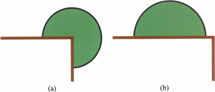
A spherical case where Theorem 2.1 does not apply and a spherical droplet is not the absolute minimum is a drop on the exterior of a corner, as shown in figure 2.4(a). The domain involved is the exterior of the corner, which is not convex, thus making Theorem 2.1 inapplicable. The corner droplet has higher energy than a spherical droplet fully on one plane side of the cornet The corner droplet is an equilibrium shape, but an unstable equilibrium; it is unstable to creeping to one side or the other.
Figure 2.4 Two competing configurations for minimum energy exterior to a corner. (a) Symmetric round bubble at the corner. (b) Round bubble entirely on one side. The latter has lower pressure, and lower energy.
2.3 Symmetrization and the Rouloids
2.3.1 Steiner Symmetrization
Unfortunately, spherical shapes do not solve all liquid problems, particularly the common case of a liquid bridge between fixed parallel planes. But is is possible to show that the minimum energy bridge must be rotationally symmetric. Jakob Steiner in 1842 published [4] an argument (made rigorous by others later) that if one took a non-rotationally-symmetric liquid shape, sliced it into infinitesimally thin parallel layers, and re-formed each layer into a circular disk of equal area about a common axis (fig. 2.5). then the result will have less surface area than the original. It works regardless of holes or interior bubbles or disconnected pieces. This process is known as Steiner symmetrization. It does not itself produce the minimum energy configuration, but applying it to any proposed minimum shows that the minimum must be rotationally symmetric.
Figure 2.5 2D example of Steiner symmetrization. (a) Initial shape between parallel lines. (b) Symmetrized shape, with less surface length.

If the slicing is horizontal, then the presence of gravity does not affect the argument, since pieces of liquid only move horizontally. Note that even though the symmetrization process does not necessarily preserve contact angles, it does preserve contact areas on the planes, and hence symmetrization does decrease total energy.
2.3.2 Rouloids
Delaunay [5] found all the surfaces of constant mean curvature (i.e. zero gravity) that are surfaces of revolution about an axis. They are spheres, cylinders, catenoids, unduloids, and nodoids. Planes perpendicular to the axis are also technically part of this group. These surfaces collectively are known as “rouloids”, since their generating curves, known as roulettes (fig. 2.6), may be formed by tracing the path of the focus of a conic section as it rolls along the axis. A java applet illustrating the rolling conies may be found at http://www.susqu.edu/brakke/roulades/roulades.html.
Figure 2.6 Roulette curves: (a) The catenary. (b) A nodary. (c) An undulary. The straight horizontal lines are the axes the conic rolls on.

Refer to the papers of Vogel [6]-[10] for an extensive discussion of the stability of rouloid liquid bridges.
2.3.2.1 The Sphere
The sphere is well-known to be the surface of least area that encloses a given volume. There are numerous proofs of this, but my favorite is given in Theorem 2.3 below.
As a roulette, the generating curve is a semi-circle, which may be generated by rotating a radial segment about the center of the circle. The segment may be viewed as a degenerate ellipse of zero minor axis, with its foci at its endpoints. Technically, a segment that rotates indefinitely (as in the other roulettes) generates a sequence of tangent spheres.
2.3.2.2 The Cylinder
The roulette for a cylinder of radius R is the straight line parallel to the axis generated by the center of a circle of radius R rolling on the axis. The sectional curvatures of the cylinder are zero parallel to the axis and 1/R perpendicular to the axis.
If a cylinder of liquid gets too long, it develops an instability known as the Rayleigh-Plateau instability (more commonly, just Rayleigh instability). If the ends are fixed, then the critical length is equal to the circumference, and the mode of instability is a neck forming near one end and a bulge forming near the other, as shown in fig. 2.8(a). Once the instability starts, the neck will continue to shrink until it pinches off. It does not reach a stable unduloid shape.
Figure 2.7 Cylinder of radius R. (a) Critical length 2πR for fixed ends, (b) Critical length πR for free ends on planes with 90 degree contact angles.

Figure 2.8 Rayleigh instability modes. (a) Fixed ends. (b) Free ends.

If the cylinder ends are free to move on parallel planes with contact angle 90°, then the critical length is half the circumference, with the unstable mode having a neck at one end and a bulge at the other, as in figure 2.8b.
The other rouloid surfaces described here have the same general stability pattern, complicated a bit by the non-uniformity along the axis.
2.3.2.3 The Catenoid
The catenary curve (fig. 2.6a) is famous as the curve made by a hanging chain, and it has the simple formula y = cosh x. It is the roulette formed by the focus of a parabola rolling on the axis. The corresponding surface of revolution, the catenoid, is notable for having zero mean curvature. It is the shape made by a soap film between two parallel rings.
2.3.2.4 Unduloids
The undulary curve (fig. 2.6c) is formed by the focus of an ellipse rolling on the axis. An undulary can be expressed in parametric form using elliptic integrals [11]. The corresponding surface of revolution is called an unduloid. For fixed ends, the critical length for stability is one period, as shown in figure 2.10b. For free ends, the critical length is about half that; Vogel [6] has shown the critical length corresponds to the points of inflection in the undulary curve.
Figure 2.9 Catenoid.

Figure 2.10 Unduloids. (a) Two periods of an unduluoid. (b),(c) Critically stable unduloids for fixed ends. (d),(e) Critically stable unduloids for free ends on planes with appropriate contact angles.

2.3.2.5 Nodoids
A nodary curve (fig. 2.6b) is generated by a focus of a hyperbola rolling on the axis. The rolling actually involves both branches of the hyperbola alternately being tangent to the axis, with the point of contact moving from one infinity to the other as the focus moves a finite distance. A nodary intersects itself. A nodary curve can be expressed in parametric form using elliptic integrals [11].
The corresponding surface of revolution is the nodoid, as shown in figure 2.11(a). Due to the self-intersections, arbitrary length nodiods do not make sense as liquid surfaces. Two situations arise: the surface is an “outer” piece of nodoid (fig. 2.11b) or it is an “inner” piece of nodoid (fig. 2.11c). Note the interior of the inner piece corresponds to the exterior of the outer piece, so the inner piece has negative mean curvature. Note that the inner nodoid is the only rouloid that has negative mean curvature, hence contains a liquid with negative pressure.
Figure 2.11 Nodoids. (a) Two periods of a nodoid, cross-section. (b) A segment of “outer” nodoid. (c) A segment of “inner” nodoid, enlarged.

Nodiods are stable up to where the surface tangent goes perpendicular to the axis, both fixed and free ends. For an unstable outer nodoid with fixed ends, bulging back beyond the fixed ends, the mode of instability is to form an asymmetric bulge to one side, which becomes stable. An inner nodoid that goes beyond stability does a symmetric neck collapse.
2.3.3 Rouloid Summary
A rouloid may be conveniently specified by giving its radius at a point where the generator is parallel to the axis and the pressure. The following table lists the rouloids in pressure order for said radius being 1.
Table 2.1 Properties of rouloids, in pressure order, for radius 1 where the roulette curve tangent is parallel to the axis. The major and minor axis refer to the conic section that does the rolling.

2.4 Increasing Pressure and Stability
There is another technique of proving regions are absolutely energy minimizing that applies to a distinct class of surfaces from the Gromov proof. In the Gromov proof, the regions were spherical, and have the property that the pressure decreases as the volume increases. If one has a family of surfaces that behave in the opposite manner, having pressure increase as volume increases, then one can conclude they are absolutely energy minimizing surfaces. Also, in contrast to Gromov’s proof, this technique can incorporate gravitational energy.
The theorem involves the notion of “foliation” of a region by surfaces. A family of surfaces foliates a region if every point of the region is on exactly one of the surfaces; think of the leaves of a book as foliating the volume of the book, or elevation contours foliating a topographic map. Note that gravity is easily incorporated in the theorem (the G(X) can be taken to be the gravitational potential energy).
Theorem 2.3. Let Ω be a domain of space with its boundary ∂Ω having designated contact surface tension ![]() . Suppose
. Suppose ![]() is a scalar potential energy density on Ω. Suppose that Wt is a nested family of regions of Ω such that Ω is foliated with surfaces ∂Wt such that each ∂Wt meets the contact angle condition at the triple line where it meets ∂Ω. Further suppose there is a monotone increasing scalar function h(t) such that the mean curvature of
is a scalar potential energy density on Ω. Suppose that Wt is a nested family of regions of Ω such that Ω is foliated with surfaces ∂Wt such that each ∂Wt meets the contact angle condition at the triple line where it meets ∂Ω. Further suppose there is a monotone increasing scalar function h(t) such that the mean curvature of ![]() on the free part of ∂Wt (i.e. h(t) is the pressure at height zero). Then each Wt is the minimum energy region in Ω among all regions of the same volume.
on the free part of ∂Wt (i.e. h(t) is the pressure at height zero). Then each Wt is the minimum energy region in Ω among all regions of the same volume.
Proof. Let ![]() be the exterior unit normal vectorfield at each point of each ∂Wt. Then we can deduce the energy of a region Wt is the integral of h over the interior:
be the exterior unit normal vectorfield at each point of each ∂Wt. Then we can deduce the energy of a region Wt is the integral of h over the interior:
(2.11) ![]()
(2.12) ![]()
(2.13) ![]()
(2.14) ![]()
(2.15) ![]()
Since each point of Ω. is on exactly one leaf ∂Wt, one may also view h as a function of ![]()
![]() Ω, so one can refer to
Ω, so one can refer to ![]() . Let it be noted that Wt occupies the exactly the region of
. Let it be noted that Wt occupies the exactly the region of ![]() and thus has the lowest integral of
and thus has the lowest integral of ![]() over all regions of equal volume.
over all regions of equal volume.
Now let V be a region of Ω. with the same volume as some Wt. Then
(2.16) ![]()
(2.17) ![]()
(2.18) ![]()
(2.19) ![]()
(2.20) ![]()
(2.21) ![]()
(2.22) ![]()
2.4.1 Wedge
As an application of Theorem 2.3, consider liquid in a wedge such that the sum of the wedge angle and the two contact angles is less than 180°. Then there is a concave circular equilibrium (this could be a purely 2D example, or the cross-section of a 3D wedge with 90° contact-angle side planes). By geometric similarity, as the amount of liquid increases, the circle radius gets larger and the pressure increases (note the liquid is on the concave side of the circular arc, hence the pressure is proportional to the negative inverse of the radius). Thus Theorem 2.3 shows that this configuration is minimal energy, hence stable. In particular, in 3D such a liquid shape is stable for any length wedge.
2.4.2 In a Square
Consider a liquid in a square 2D box, where the contact angle is less than 45°. Then the liquid can make concave regions in the corners. A foliation can be done using circular arcs of increasing radius in the corners, at least until the arcs meet in the middles of the edges. Thus Theorem 2.3 shows that having the liquid spread equally in the corners is the minimum energy configuration, as opposed to, say, unequal liquid in the corners. For larger fluid volumes, corners can join up. If the contact angle is 0°, then the foliation can be continued to where the corners join up and further into circles in the interior, showing there is a continuum of stable shapes. But if the contact angle is not 0°, then the foliation cannot be continued, and there is a jump in the stable shape when the liquid meets at the centers of edges. But as long as the fluid stays within the corner foliation, it is stable, even though there is a lower energy shape extending outside the foliation. The same kind of analysis can be done with a small amount of liquid in the corners and edges of a 3D box.
Figure 2.12 (a) Negative pressure liquid in a wedge. (b) Foliation of wedge by increasing pressure surfaces (i.e. less negative pressure).
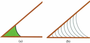
Figure 2.13 Liquid in corners of a square. (a) Since smaller corner drops have more negative pressure, the minimum energy is equalized corners. (b) A foliation of the neighborhood of the fluid.

2.4.3 Round Well
Consider liquid in the bottom of a round well round well (fig. 2.14). If the contact angles on the floor and wall add up to more than 90°, then it is possible for the liquid surface to intersect the floor/wall junction and make an isolated blob (fig. 2.14a). For a larger volume, the minimal energy configuration will be a ring around the bottom (much like fig. 2.14b), but note that if the volume of the ring gets too small, it will be subject to the double-bubble instability discussed below. If the sum of the floor and wall contact angles add to less than 90°, then the isolated blob of figure 2.14a is impossible, and a foliation argument shows that the uniform ring as in figure 2.14b is stable no matter how little liquid there is. As in the box example, if the contact angle is 0°, a single foliation can handle the transition to a fully covered bottom, otherwise there is a jump to the fully covered bottom, as in 2.14c. Note that once the bottom is covered, the foliation consists of congruent parallel surfaces until the contact line reaches the top of the well, but such equal-pressure surfaces are fine for Theorem 2.3. After the contact line reaches the top, there can be further spherical cap foliation surfaces pinned at the top of the well, with increasing pressure until the foliations reach a hemisphere. For volume beyond that, the foliation argument does not work.
Figure 2.14 Flat-bottomed round well. (a) Drop on side of bottom, needs sum of contact angles greater than 90 degrees. (b) Ring of liquid around bottom of well, sum of contact angles less than 90 degrees, or larger volume. (c) Full bottom of well.

2.4.4 Square Well
Consider liquid in the bottom of a square well (fig. 2.15). If the sum of the floor and wall contact angles is greater than 90°, then the contact line can cross the wall/floor junction, and the liquid might cover 1, 2, 3, or 4 corners (or even be in separated pieces in various combinations). But if the sum of the contact angles is less than 90°, then only a concave version of figure 2.15.d is possible. As with the round well, a foliation argument can be made to show figure 2.15.d is minimal energy, along with various levels of symmetric filling.
Figure 2.15 Liquid in the bottom of a square well (a) Occupying one comer. (b) Occupying two corners. (c) Occupying three corners. (d) Occupying four corners.

2.5 The Double-Bubble Instability
The double-bubble instability is epitomized by two equal-diameter spherical soap bubbles joined by a tube (fig. 2.16). The configuration is in equilibrium, since the bubble radii, and hence pressures, are equal. But if there is the slightest disturbance so that one bubble becomes larger, then the pressure in the smaller bubble is higher, and air will be pumped from the smaller bubble to the larger, amplifying the difference. The transfer of air will stop only when the smaller bubble has collapsed to a small spherical cap on the tube end of equal radius to the large bubble.
Figure 2.16 The double bubble instability, (a) Two equal bubbles connected by a pipe. (b) Collapse of the left bubble in progress, as it pumps air to the right bubble. (c) Final stable state, with both bubbles having the same curvature.

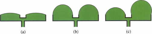
A “double-bubble pipe” (fig. 2.17) makes a nice demonstration of both the principles of increasing-pressure stability and the double-bubble instability. When the pipe is first drawn out of a soap solution, there are two flat, zero-pressure films across the pipe openings. As one blows air into the pipe, the two bubbles start inflating equally. This is because initially the volume increase leads to increasing pressure, so if one bubble is larger than the other, the larger bubble pumps air into the smaller bubble. But when the bubbles reach hemispheres, larger volume means lower pressure, so the double-bubble instability takes over, and as one blows more air in, one bubble shrinks and the other gets larger. For a double-bubble pipe, this transition happens smoothly, but for a triple-bubble pipe there is a sudden jump as the bubbles reach hemispheres, with two bubbles collapsing and one bubble enlarging.
Figure 2.17 The double bubble pipe for blowing two soap bubbles simultaneously. (a) For low volume, there are two identical spherical cap bubbles. (b) Hemispherical bubbles are the maximum volume for symmetric bubbles. (c) Above the critical volume, the stable configuration is one small bubble and one large bubble.
2.5.1 Conditions for the Double-bubble Instability
The condition for the double-bubble instability to happen is for there to be two connected regions of liquid at the same pressure, but for each of which the pressure decreases as the volume increases. The regions do not have to be spherical bubbles, and they don’t have to be the same shapes. Any shapes will do, as long as pressure decreases with volume. The argument still applies that any perturbation increasing the volume of one region at the expense of the other will lead to higher pressure in the smaller region, making it pump liquid to the larger region until pressures are equalized. The regions need not be separated by a rigid pipe; as examples below show, two parts of one liquid shape may function as separate regions and give rise to a double-bubble instability.
2.5.2 Plateau-Rayleigh Instability
The Plateau-Rayleigh instability (often called just the Rayleigh instability) says that a liquid cylinder with fixed ends becomes unstable to necking when its length reaches π times its diameter. This may be seen as an instance of the double-bubble instability. Consider two separate cylinders of liquid of the same radius. If they were connected by a small tube, obviously they would be subject to the double bubble instability. If one considered two distant segments of one cylinder, one could almost consider them separate regions, since the segments could change size with only a very gradual change in the radius between them, and hence only a small additional area due to a sloped surface. For a short cylinder, the extra area due to the slope between the regions overcomes the area savings due to the double-bubble instability, so short cylinders are stable. It so happens that the critical point where the double-bubble instability overcomes the slope area happens when the cylinder length is 7t times the radius, for fixed cylinder ends, say on perfectly wetting circular pads.
2.5.3 Plateau-Rayleigh Instability in Corners and Grooves
Liquid in a corner or groove between two planes can form an equilibrium convex cylindrical surface, if the sum of the corner angle and the contact angles on the walls exceed 180° (the Concus-Finn condition). Here it is assumed the contact lines on the walls are free to move. Just as for a complete cylinder, if the surface is long enough, a necking instability will develop. Evolver calculations show that the ratio of critical length to radius of curvature grows as the angle sum approaches 180°.
2.5.4 Instability of a Cylinder on a Hydrophilic Strip
Consider a perfectly wetting horizontal strip with liquid forming a cylindrical section above it, with contact lines pinned at the sides of the strip. As with an isolated cylinder, different parts of the liquid on the strip may be considered different regions. The analogy is to the double-bubble pipe, rather than the original double bubble. For small volumes of liquid, the top of the liquid is nearly flat, with small pressure. As volume increases, the pressure increases, and hence the cylindrical shape is stable for an arbitrary length strip. But when the liquid goes beyond a semicircular shape, the double-bubble instability becomes active and necking takes place. For a long enough strip, necking may start at several places, but the analogy is more like the triple-bubble pipe, and one large blob grows suddenly at the expense of other potential blobs.
2.5.5 Double-bubble Instability in Bulging Liquid Bridge
Consider a liquid bridge between two circular parallel pads, such that the pads are close enough that the liquid squeezes outside the ideal cylinder between the pads. As long as the bulge is small enough that it does not protrude below the level of the lower pad or above the level of the upper pad, then the Steiner symmetrization argument shows that the circularly symmetric shape (a section of unduloid, sphere, or nodiod) will be stable. But if the bulge does penetrate the pad levels, then it becomes susceptible to a double-bubble instability, with one side bulging out and the opposite side moving inward.
2.5.6 Lower-pressure Comparison Theorem
A version of the double-bubble argument can often be used to decide between two competitors for the lowest energy configuration without an explicit calculation of energies. In the corner-drop example above (§2.2.6), a simple way to see the one-plane bubble is lower energy than the corner bubble is to note the one-plane bubble clearly has a larger radius and thus a lower pressure. Imagining a thin pipeline between the two, the higher pressure in the corner would drive liquid to the one-plane drop, ultimately leaving the one-plane drop with all the liquid. This argument is not quite air-tight, but can be made so if the two shapes behave well as their size changes. In particular, if one can grow each shape from zero volume and zero energy such that for each volume the first shape has lower pressure than the second, then the first shape will have lower energy. This follows directly from the fact that pressure is the rate of change of energy with respect to volume.
2.6 Conclusion
This chapter has discussed various methods of detecting the stability of liquid shapes. To summarize:
- A spherical drop in a convex region minimizes energy when the sphere is located so it intersects all the walls at the proper contact angle.
- If the walls of a convex region are mobile, the liquid will move them to a shape where the drop is spherical.
- If the configuration is such that Steiner symmetrization can be done, then the minimum energy shape will be rotationally symmetric.
- If a region can be foliated with constant-pressure surfaces whose pressure increases with volume, then each foliation is the surface of a region with minimum energy.
- If a liquid has separate regions where the pressure decreases as volume increases, then the liquid may be subject to the double-bubble instability, in which one region increases at the expense of the other.
- If there are two competing shapes for minimum energy, the lower-pressure shape is likely to be best.
2.7 References
[1] H. Federer. Geometric Measure Theory. Springer-Verlag, New York, 1969.
[2] F. Morgan. Geometric Measure Theory: A Beginner’s Guide. 4th ed. Academic Press, San Diego, 2008.
[3] M. Gromov, “Isoperimetric inequalities in Riemannian manifolds,” Appendix I to Asymptotic Theory of Finite Dimensional Normed Spaces by V. D. Milman and G. Schechtman, Lecture Notes in Mathematics No. 1200, Springer-Verlag, New York, 1986.
[4] Jakob Steiner, presented to Berlin Academy of Science, 1836.
[5] C. Delaunay, “Sur la surface de revolution dont la courbure moyenne est constante,” Jour, de Mathématiques 6, pp. 309–320, 1841.
[6] T. Vogel, “Stability of a drop trapped between two parallel planes”, SIAM J. Appl. Math. 47(3), pp. 516–525, 1987.
[7] T. Vogel, “Stability of a drop trapped between parallel planes II: general contact angles,” SIAM J. Appl. Math. 49(4), pp. 1009–1028, 1989.
[8] T. Vogel and R. Finn, “On the volume infimum for liquid bridges,” Zeitschrift fuer Analysis und Ihre Anwendungen 11, pp. 3–23 (1992).
[9] T. Vogel, “Comments on radially symmetric liquid bridges with inflected profiles”, Discrete and Continuous Dynamical Systems, Supplemental Volume, pp. 862–867, 2005.
[10] T. Vogel, “Convex, rotationally symmetric bridges between spheres”, Pac. J. Math. 224(2), pp. 367–377, 2006.
[11] M. ![]() iri
iri![]() , “Notes on constant mean curvature surfaces and their graphical presentation,” Filomat 23(2), pp. 97–107, 2009.
, “Notes on constant mean curvature surfaces and their graphical presentation,” Filomat 23(2), pp. 97–107, 2009.